DOI http://dx.doi.org/10.11004/kosacs.2015.6.3.050
MMA 이중 플랜지를 갖는 GFRP 복합관 구조거동에 관한 실험 연구 (II)
지효선1 · El-Badry Mamdouh2
대원대학교 철도건설과 부교수1, 캘거리대학교 토목공학과 교수2
An experimental study on structural behaviour of the MMA double wide flanged GFRP pipe composite structures (II)
Ji, Hyo-Seon1 · El-Badry Mamdouh2
1Associate Professor, Department of Civil & Railroad Engineering, Daewon University College, Chungbuk-Do, South Korea
2Professor, Department of Civil Engineering, University of Calgary, Alberta, Canada
Abstract: This paper presents on the structural behavior of the the methyl methacrylate monomer (MMA) double wide flanged the glass fiber-reinforced polymer(GFRP) pipe composite structures for the manhole raise. The evaluation of structural performance on this composite structure was conducted by the axial load, fatigue load, and ultimate load test.
The assessment indicates that the MMA double wide flanged GFRP pipe composite structures was confirmed safety, durability and reliability in result as expected. It was found that this composite structure was able to short working times to around 30-50% and construction costs to around 10-23% with compare other construction methods. Also, environmental pollution and civil complaints will be prevented because there will be no longer any noises, vibrations, dust, or construction wastes.
Key Words: structural behaviour, manhole raise, MMA, GFRP, axial load test, fatigue load test
주요어: 포장, 맨홀인상, GFRP 관, 복합신소재구조, MMA, 축하중 실험
Corresponding author: Ji, Hyo-Seon
Department of Civi & Railroad Engineering, Daewon University College, 274 Daehak-Ro, Jecheon-Si, Chungbuk-Do, 390-702, Korea.
Tel: +82-43-649-3266, Fax: +82-43-649-3681, E-mail:[email protected]
Received August 31, 2015 / Revised September 11, 2015 / Accepted September 19, 2015
1. INTRODUCTION
Most of the repair technology for the manhole raise due to the overlaid road pavement has been has been using concrete composite structures. The repair technology by using the concrete composite structures for manhole raise has been required in much construction work such as the assembling moulds, casting and aging. Recently, Seo et al. (2012) have developed an environmental-friendly manhole repair technology which can raise manhole to the regular height with rapid construction and minimum disruption to public traffic flow. But the manhole repair technology has been showing the structural problems such as
around failure of the manhole raise due to the repeated truck load. In this study, the manhole repairing composite structures by using Fiber Reinforced Polymer(FRP) materials are considered as a potential solution to the repair problem of manhole due to the material’s superior properties, such as high strength or strength per unit weight, fast construction, easy installation and reduction of maintenance costs. (Son et al., 2012; CSA, 2002) FRP materials have recently been used in the area of civil engineering constructions (Son et al., 2013).
In order to resolve such problems, we have developed the new composite structures for the manhole raise by using a GFRP pipe. The technology can raise manhole to the regular height of the overlaid road pavement elevation with rapid construction, and
minimum disruption to public traffic flow. This technology of manhole repair is method completed by double wide flanged GFRP pipe composite structures in order to raise manhole to the regular height. This flange member is made of methyl methacrylate monomer (MMA) resin mortar, composed of methyl methacrylate (MMA) resin, fine heavy calcium carbonic, and fine aggregate. The remarkable characteristics of MMA resin mortar are its high early strength, curing even in low temperature, and high abrasion resistance. The MMA resin is low viscosity, and flexible resin for use as a binder for polymer mortar (Omata et al., 1997; ACI, 2008a). The MMA resin is ideal for making flange member that will be connected to the GFRP pipe composite structures.
However, due to the lack of data for performance and durability of the MMA double wide flanged GFRP pipe composite structures, it is not common practice for pavement engineers to use the MMA double wide flanged GFRP pipe composite structures to fix and raise manhole.
Many researchers have been conducting for the double-skinned GFRP tubular short columns similar to this study. Wei et al. (1998) report on performance of new sandwich tube under axial loading for compression member in offshore construction in 1995.
Mirmiran et al. (1998, 1997) report on effect of parameters, and behavior of concrete columns confined by fiber composites in 1998. Theriault et al. (2000) report on design equations for axially loaded reinforced concrete columns strengthening with FRP wraps in 2000. Fam et al. (2001a, 2001b) report on confinement model, and behavior of axially loaded concrete filled FRP tubes in 2001. Carey et al. (2005) report on the axial behavior and modeling of confined small, medium, and large scale circular section with CFRP in 2005. Zhu et al. (2005) report on effect of column parameters on axial compression behavior of concrete-filled FRP tube in 2005. Wu et al. (2006) report on strength and ductility of concrete cylinders confined with FRP composites in 2006.
Chaallal et al. (2006) report on circular columns confined with FRP experimental versus predictions of models and guidelines in 2006. Son et al. (2008) report on finite element modeling of hollow and concrete-filled fiber composite tuebe in flexure in 2008. Mohamed et al. (2010) report on axial load capacity of concrete-filled FRP tube columns:
experimental vs theoretical prediction in 2010. Lee et al. (2013) performed an experimental study for confined concrete double skinned composite tubular columns in 2013.
The main objective of this paper is to describe the structural behavior assessment of the MMA double wide flanged GFRP pipe composite structures subjected to axial loads based on an experimental investigation. The behavior assessments for this the MMA double wide flanged GFRP pipe composite structures are based on the axial load test, fatigue test, and ultimate load failure test. The assessment indicates that this technology for manhole raise by using the MMA double wide flanged GFRP pipe composite structures was confirmed safety, durability and reliability in result as expected. In this paper, we found that this environmental-friendly repair technology by using the MMA double wide flanged GFRP pipe composite structures was able to short working times to around 20% and construction costs to around 50% with compare other construction methods.
Also, environmental pollution and civil complaints will be prevented because there will be no longer any noises, vibrations, dust, or construction wastes.
2. EXPERIMENTAL PROGRAM
To investigate structural characteristics of the proposed MMA double wide flanged GFRP pipe composite structures for a manhole raise construction in road pavement construction and to verify that the proposed MMA double wide flanged GFRP pipe composite structures meets all the design requirements, the following three different structural tests were conducted on the prototype MMA double wide flanged GFRP pipe composite structures: (1) axial load test;
(2) fatigue load test to inspect the strength degradation; (3) ultimate load test to failure under static loadings.
2.1 Fabrication of specimens
The prototype MMA double wide flanged GFRP pipe composite structures sample was fabricated for conducting the axial load test, fatigue load, and ultimate load tests. The detailed drawing samples for the composite structures of manhole raise as shown in Fig. 1.
Fig. 1 The proposed MMA wide doubled flanged GFRP pipe composites structures for a manhole raise(all dimensions in mm)
Fig. 1 were fabricated as following sequences: 1) manufacture of wide flanged tubular ring by using MMA resin mortar; 2) manufacture of composite structures with the GFRP pipe inserted the double wide flanged tubular ring; 3) manufacture of double wide flanged GFRP pipe composite structures filled with the cement mortar to the edge of ring.
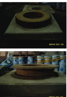
The MMA double wide flanged GFRP pipe composite structures was fabricated as shown in Fig. 2.
Fig. 2 Specimen of composite structures for manhole raise
The total of 9 specimens are fabricated. The specimens can be separated into 3 types: 1) double flanged, single-skinned GFRP pipe composite structure (type I) as shown in upper side of Fig. 6, 2) double flanged, doubled-skinned mortar filled GFRP pipe composite structure (type II) as shown in lower side of Fig. 6, 3) double flanged, single-skinned mortar filled GFRP pipe composite structure (type III) as shown in Fig. 3.
Fig. 3 Specimen of composite structures for ultimate load test
2.2 Experimental setup and instrumentation
2.2.1. Axial load test
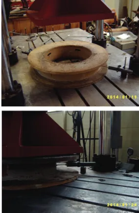
Firstly, static axial load tests were conducted on the prototype MMA double wide flanged GFRP pipe composite structures sample. In case of the axial load test, a Servo electro-hydraulic actuator of a loading capacity of 1MN was used for the compressive tests under a range of loading. The axial load test setup for MMA double wide flanged GFRP pipe composite structures is shown in Fig. 4.
Fig. 4 Experimental setup (static load test)
The MMA double wide flanged GFRP pipe composite structures test sample was tested under the axial loading. The static load was applied to the composite structures through a ×
steel loading frame as shown in Fig. 5.
Fig. 5 View of loading frame for axial load test
A steel loading frame was placed on the composite structures so as to apply force from actuator and have that force transmitted to the steel loading frame on center. Six MMA double wide flanged GFRP pipe composite structures specimens were tested. Load, deflection and strain were the general measurements in this experimental program. The displacement using linear variable deflection transducers (LVDTs) at two points along the midsection and strains using strain gauges at the outer face, and inner of the specimen were measured as shown in Fig 6.
Fig. 6 View of attachment of LVDTs and strain gauges at a test sample
The location of strain gauges are at the outer face of the specimen (O1, O2, O3, O4), and the inner face (I5, I6, I7, I8) and the location of LVDTs at two points along the midsection represented by D1, D2 at outside of GFRP surface at half diameter are shown in Fig. 7.
Fig. 7 View of location of LVDTs and strain gauges
2.2.2. Fatigue load test
Secondly, MMA double wide flanged GFRP pipe composite structures should consider the effects of fatigue loading. In order to evaluate the fatigue
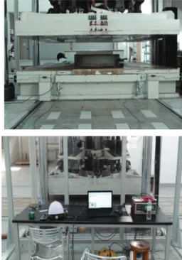
resistance of the MMA double wide flanged GFRP pipe composite structures' predicted service life, a fatigue loading test was performed. The load was applied using a Servo Fatigue electro-hydraulic actuator permanently fixed to a framework. The Servo Fatigue electro-hydraulic actuator had a loading capacity of 1MN like the static axial load test. This test was controlled using a digital servo controller. A digital controller was used to control the load range, frequency of loading and the number of cycles of the hydraulic actuator. The fatigue load test setup for MMA double wide flanged GFRP pipe composite structures is shown in Fig. 8.
Fig. 8 Experimental setup (fatigue load test)
The number of cycles for fatigue load test are 0.5 million. Two MMA double wide flanged GFRP pipe composite structures specimens were tested. The locations of displacement, and strain measurement are same to the axial load test.
2.2.3. Ultimate load test
Finally, in case of the ultimate load test, a UTM of a loading capacity of 5MN was used for an ultimate load test. The ultimate load test was to examine the failure strength and failure progression. The specimen
for the ultimate load test was fabricated in the double wide flanged GFRP pipe composite structures filled with the cement mortar to the edge of ring as shown in Fig. 3. The ultimate load test setup for MMA double wide flanged GFRP pipe composite structures is shown in Fig. 9.
Fig. 9 Experimental setup (ultimate load test)
The displacement using linear variable deflection transducers (LVDTs) at two points along the midsection and strains using strain gauges at the outer face of the specimen were measured as shown in Fig 10.
Fig. 10 Location of LVDTs and strain gauges
2.3 Experimental procedure and results 2.3.1. Axial load test
The test samples were preloaded up to 100 kN at a
loading rate of 2.2 kN to 4.4 kN per minute and then released. The test specimens were loaded in the cycle three times at regular intervals. This operation was to ensure the loading edges, remained in proper contact with the test specimen. The first step of axial load test was a design load test for observing behavior of the MMA double wide flanged GFRP pipe composite structures up to the truck wheel load 122.3 kN, which 94.08 (kN) plus a 30% impact allowance (MOCT, 2002), and followed by a load up to 903 kN due to the hydraulic actuator with load capacity of 1,000 kN.
Table 1 shows the comparison of displacement and strain of specimens in type I, not to be filled with a mortar.
Table 1. Displacements and strains from axial load test (load=122.3kN) in Type I
Load cycling (cycles)
Mid-height lateral deflection (mm)
Mid-height transverse strain (micro strain) Left
centerline D1
Right centerline
D2
GFRP pipe O3
GFRP pipe I7
Specimen 1 0.07 0.04 114 -
Specimen 2 0.04 0.01 107 -
Specimen 3 0.13 0.15 - 158
Mean value 0.08 0.07 111 158
Table 2 shows the comparison of displacement and strain of specimens in type II, to be filled with a mortar.
Table 2. Displacements and strains from axial load test (load=122.3kN) in Type II
Load cycling
Mid-height lateral deflection (mm)
Mid-height transverse strain
(micro strain)
(cycles)
Left centerline
D1
Right centerline
D2
GFRP pipe
I5
GFRP pipe
I7
Specimen 1 0.09 0.09 997 512
Specimen 2 0.06 0.14 1,443 430
Specimen 3 0.23 0.01 315 382
Mean value 0.13 0.08 918 441
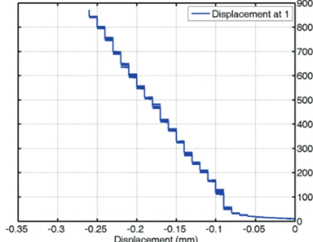
The performance criteria for strength for the MMA double wide flanged GFRP pipe composite structures was based on the allowable strength criteria. The displacement at the mid-height of the column was 0.35mm at the service load 902.8 kN. The load-displacement curve up to 900 kN is shown at two points along the mid-height of the column in Fig.
11.
Fig. 11 Load-displacement response from static load test
After unloading from the applied load of 903 kN, some residual displacement was not observed. The load-strain curve up to 900 kN at location of the outer face of the specimen (O3), and the inner face (I7) is shown in Fig. 12, and Fig. 13.
Fig. 12 Load-strain response from static load test (O3)
Fig. 13 Load-strain response from static load test (I7) The strain at location of the outer face of the
specimen (O3) is recorded about 111 in the load of 122.3 kN of the standard truck wheel load [12]. The strain at location of the inner face of the specimen (I7) is recorded about 158 in the load of 122.3 kN.
The stresses calculated from this strains was from 3.6 MPa in the inner face of the specimen, and 5.2 MPa in the outer face of the specimen. These strains are less than the allowable strain, 20% of maximum strain of the FRP coupon test, 3930 in the GFRP pipe made by the HANKUK FIBER GROUP (2004).
2.3.2. Fatigue load test
The MMA double wide flanged GFRP pipe composite structures should consider the effects of fatigue loading. In order to evaluate the fatigue resistance of the MMA double wide flanged GFRP pipe composite structures' predicted service life, a fatigue loading test was performed. A manhole on road pavement should carry over 0.5 million vehicles for more than 3-year according to Korea standards specifications (MOCT, 2002). The load was applied using a Servo electro-hydraulic actuator permanently fixed to a framework. The actuator had a loading capacity of 1000 kN. This test was controlled using a digital servo controller. A digital servo controller was used to control the load range, frequency of loading and the number of cycles of the hydraulic actuator. A spreader box of a × steel loading frame was utilized to apply the load at the top flanged GFRP pipe composite structures. This spreader box of a steel loading frame was supported by the top flanged GFRP pipe composite structures. This the top flanged GFRP pipe composite structures sample was subjected to fatigue loading for 500,000 cycles that may represent years of actual service for a manhole.
The load was cycled between the maximum load of 150 kN and the minimum load of 30 kN at a frequency of 3Hz under load control. The loading cycles simulate passage of the rear axle load of a standard truck including impact factor 1.3, which is 122.4 kN (MOCT, 2002). In the case of fatigue test, each test sample was instrumented with both strain gages and displacement transducers. The deflection, strain for the test sample were recorded during the test using a high-speed data acquisition system.
The static tests were conducted on the test sample after 500,000 cycles of the fatigue load test. The
load-displacement curves, and load-strain curves at several composite structures' locations during the static tests after 0.5 million cycles were shown in Fig. 14, and 15.
Fig. 14 Load-displacement response after fatigue cycling (500,000)
Fig. 15 Load-strain response after fatigue cycling (500,000)
From the results the deflection and strain response remained fairly constant for all of the axial load tests, and the MMA double wide flanged GFRP pipe composite structures was shown no apparent changes in strength of the structure. And deterioration of the MMA double wide flanged GFRP pipe composite structures caused by the fatigue loading was not inspected at composite structures. From the inspection, no visible signs of deterioration to the MMA double wide flanged GFRP pipe composite structures and
MMA resin mortar ring were observed. A comparison of displacement, and strain measurements for the axial load test conducted after 500,000 fatigue cycles are shown in Fig 16, and 17.
The mid-height displacement at 150kN for test after fatigue cycling was 0.04mm and the maximum measured strain at GFRP pipe of the mid-height was 1918 in the loading direction.
Fig. 16 Comparison of load-displacement between static load test and fatigue load test
Fig. 17 Comparison of load-strain between static load test and fatigue load test
The strength of the MMA double wide flanged GFRP pipe composite structures after the fatigue test was reduced sharply when compared to that calculated from strains measured in the design load test as shown in Table 3.
Table 3. Comparison of displacement and strain between static test and fatigue test (load = 122.3kN)
Load cycling (cycles)
Mid-height lateral deflection (mm)
Mid-height transverse strain (micro strain) Left
centerline D1
Right centerline
D2
GFRP pipe
O3
GFRP pipe I7
0 0.09 0.04 114 -
500,000 0.10 0.04 - 245
2.3.3. Ultimate load test
An ultimate load test for the MMA double wide flanged GFRP pipe composite structures was conducted for observing the ultimate load capacity and failure mode of the column was loaded up to 4MN using a hydraulic actuator with the load capacity of 5MN. The load-displacement, and load-strain curves are shown in Fig. 18, and 19.
Fig. 18 Load-displacement response from ultimate load test
Fig. 19 Load-strain response from ultimate load test
Table 4 shows comparison of displacement and strain for the specimens at ultimate load test. As loading was continued, displacement to a full load of 5MN became linear, and no sign of failure was obtained. The strain was increased linearly to around the load of 2.2MN, and the strain is showing about 1679. After at that load, the strain values were decreased sharply. The failure of the filled mortar was resulted in the MMA double wide flanged GFRP pipe composite structures.
Table 4. Comparison of displacement and strain at ultimate load test (load = 5,000 kN)
Load cycling Mid-height lateral deflection (mm)
Mid-height transverse strain
(micro strain)
(cycles)
Left centerline
D1
Right centerline
D2
Cement mortar
Specimen 1 0.170 0.300 1,679 -
Specimen 2 0.395 0.365 1,836 -
Specimen 3 0.055 0.150 1,827 1,436
Mean value 0.207 0.272 1,781 1,436
2.3.4. Strength capacity, stiffness, and axial ductility
The total of 3 types specimens are tested as following: 1) double flanged, single-skinned GFRP pipe composite structure (type I), 2) double flanged, doubled-skinned mortar filled GFRP pipe composite structure (type II), 3) double flanged, single-skinned mortar filled GFRP pipe composite structure (type III).
Comparison of strength capacity, and stiffness for each type described above was shown in Table 5.
Table 5. Comparison of strength capacity, and stiffness Specimen Pu(kN) Ɛp(µƐ) Ecomp(MPa)
Type I 902.8 2,955 14,455
Type II 897.7 2,296 42,800
Type III 2,182.2 1,678 40208
The strength capacity of the double wide flanged GFRP pipe composite structures is defined as the peak value of the axial loads observed in the axial loads-strain curve. The value of is the nominal
strength given as following:
(1)
where and are the cross-sectional areas of the GFRP pipe and resin mortar section, respectively.
The and are the yield strength of the GFRP pipe and the actual compressive strength of mortar.
The initial stiffness of the double wide flanged GFRP pipe composite structures is defined as the averaged initial slope of an axial load-strain curve.
It is calculated from its linear recurrence within the range of axial deformation, divided by the cross-sectional area of the double wide flanged GFRP pipe composite structures. The double wide flanged GFRP pipe composite structures stiffness, according to the theory of superposition can be expressed as following:
(2)
where and are the cross-sectional areas of the GFRP pipe and resin mortar section, respectively.
The and are the young's modulus of lamina of FRP member, and resin mortar. The stiffness properties of a lamina can be calculated by the micro-mechanics models based on several simple rules of mixtures, as shown below:
(3)
where = efficiency factor of the fiber. For unidirectional fibers, =1.0; bi-directional fibers,
=0.5; random in-plane fibers,=0.375.
=Young’s modulus of the fiber and matrix; = fiber volume fraction for each lamina. And the resin mortar.
is calculated from .
From Table 10, it is observed that the strength the type III specimen is the highest of the all types specimens, but there is showing the strength between the type I and type II. As shown in Table 10, the type II is the highest stiffness of the three types. The type III specimen was fabricated with considering construction work for the manhole raise on the road pavement.
3. FINITE-ELEMENT MODEL
A Finite Element (FE) analysis by ANSYS (2005) was carried out for the test of the MMA double wide flanged GFRP pipe composite structures sample. The MMA double wide flanged GFRP pipe composite structures were modeled by 8-node shell elements, while the MMA resin mortar ring was modeled by solid elements. The adhesive bonds between the GFRP pipe and the wide flange ring were assumed in the model as rigid connections. The overall FE model for the test specimen is shown in Fig. 24.
X YZ
X Y Z
Fig. 20 FE model of the specimen (ANSYS)
The boundary conditions in axial load test were modeled as a fix for the end support. The boundary conditions at nodes of the MMA double wide flanged GFRP pipe composite structures were modeled as constrained displacement in the vertical direction. The layer stiffness properties of laminates of GFRP pipe are calculated by a simple rule of mixtures approach from micro-mechanics models.
The FE analysis comparisons of displacement and strength results at a load of 122.3kN are shown in Tables 6.
Table 6. Comparison of displacement and strength at static test (load = 122.3 kN)
Lateral displacement
(mm) Strength (MPa)
Experiment
(mean value) 0.08 5.21
Analysis
(ANSYS) 1.13 4.58
The displacement and strength of the MMA double wide flanged GFRP pipe composite structures are compared at the maximum design load, 122.3 kN.
Generally, the test results are higher than those of the analysis, but the displacement computed at 122.3 kN was 32 % less than those measured during the tests as shown in Table 6. As the primary reason, the load transferred from the flange member was not seemed loaded the GFRP pipe through the connection between the flange and pipe unlikely the FE analysis. The predicted yield load was considered as over 900 kN.
Fig. 21, and 22 are shown the displacement, and strain of the MMA double wide flanged GFRP pipe composite structures by ANSYS.
MN MX
X YZ
-1.13613
-1.00973-.883323
-.756918-.630513
-.504108-.377703
-.251298-.124893 .001512
Fig. 21 Displacement of the specimen (ANSYS)
MN
MX
-15.4786
-13.2492-11.0198
-8.79047-6.5611
-4.33174-2.10237
.126996 2.35636 4.58573
Fig. 22 Strength of the specimen (ANSYS)
4. EVALUATION OF MMA DOUBLE WIDE FLANGED GFRP PIPE COMPOSITE
STRUCTURES PERFORMANCE
The results of the three different tests performed on the prototype of the MMA double wide flanged GFRP pipe composite structures sample were used to determine characteristics of the full-size MMA double wide flanged GFRP pipe composite structures. The test sample is not failed at over 900 kN, which is of the order of eight times the design standard wheel load.
This indicates extremely good performance of the MMA double wide flanged GFRP pipe composite structures as far as strength is concerned. The mid-height displacement of the MMA double wide flanged GFRP pipe composite structures sample at the design wheel load were 0.35mm and 0.26mm for the static load test before fatigue loading and the post-fatigue load test. The strength after the fatigue loading test was higher than the static load test as shown in Table 8. It was found that the strength of the proposed MMA double wide flanged GFRP pipe composite structures in this study was within the allowable value in the manhole's column.
It also found that this technology of manhole by using the proposed MMA double wide flanged GFRP pipe composite structures was able to short working times to around 30-50% and construction costs to around 10-23% with compare other construction methods as shown in Table 7. Also, environmental pollution and civil complaints will be prevented because there will be no longer any noises, vibrations, dust, or construction wastes.
Table 7. Comparison of costs and constructiorn times
Company Cost(₩) Construction
times(min)
A 685,687 90
B 774,314 100
C 658,238 120
Developed method 594,479 60
5. CONCLUSIONS
The behaviour of the proposed MMA double wide flanged GFRP pipe composite structures for manhole
raise was evaluated using an experimental approach.
Based on the study presented in this paper, The MMA double wide flanged GFRP pipe composite structures can meet the strength design criteria as defined in the specifications of the manhole. It was found that the strength criteria for the MMA double wide flanged GFRP pipe composite structures may be presented in terms of allowable strain for the FRP composites and allowable stress for MMA resin materials. The failure load of 900 kN was eight times the design wheel load of 122.3 kN. No reduction in strength or strength was found after 500,000 cycles of fatigue load in the design wheel load. The MMA double wide flanged GFRP pipe composite structures met the service load design criteria after fatigue cycling. The proposed technology of the MMA double wide flanged GFRP pipe composite structures for manhole raise was able to not only improve strength but also be cost-efficient compared to other technology of manhole raise . The use of MMA double wide flanged GFRP pipe composite structures utilizing materials in a combination favourable to the individual component’s strengths and characteristics was shown.
ACKNOWLEDGMENT
This work (Grants No. C0185413) was supported by Business for Cooperative R&D between Industry, Academy, and Research Institute funded Korea Small and Medium Business Administration in 2014.
References
American Concrete Institute (ACI). (2008a) "Guide for the design and construction of externally bonded FRP systems for strengthening concrete structures," ACI 440.2R-08, Farmington Hills, Mich.
ANSYS Inc. ANSYS 10.0 (2005) "documentation,"
Canonsburg, PA, USA.
Canadian Standard Association (CSA). (2002) "Design and construction of building components with fibre-reinforced polymers," CSA-S806-02, Rexdale BD, Toronto.
Carey S. A., Harries, K. A. (2005) "Axial behavior and modeling of confined small-, medium-, and large-scale circular sections with carbon
fiber-reinforced polymer jackets," ACI Struct J, 5, 102(1), pp.62–72.
Chaallal O., Hassan M., LeBlanc M. (2006) " Circular columns confined with FRP: Experimental versus predictions of models and guidelines," J Compos Constr 10(1), pp.4–12.
Fam A., Rizkalla S. H. (2001a) "Confinement model for axially loaded concrete confined by circular fiber-reinforced polymer tubes," ACI Struct J, 98(4), pp.451–461.
Fam A., Rizkalla S. H. (2001b) "Behavior of axially loaded concrete-filled circular fiber-reinforced polymer tubes," ACI Struct J, 98(3), pp.280–289 Hankuk Fiber Group (2004) www.fiber-x.com.
Lee., Kang Y.J. (2013) "Experimental study for confined concrete of double skinned composite tubular columns by uni-axial compression test," Journal of Korean Society for Advanced Composites Structures, 121(12), pp.1806-1814.(in Korean).
Mirmiran A., Shahawy M., Samaan M., El Echary H., Mastrapa J.C., Pico O. (1998) "Effect of column parameters on FRP-confined column," J Compo Constr, 2(4), pp.175–185.
Mirmiran A., Shahawy M. (1997) "Behavior of concrete column confined by FRP composites," J Struct Eng, 138(5), pp. 583–590
MOCT. (2002) "Standards specifications for highway bridge" 2nd Ed., Korea, Ministry of Construction and Transportation. (in Korean).
Mohamed H., Masmoudi R. (2010) "Axial load capacity of concrete-filled FRP tube columns: Experimental versus theoretical predictions," J Compos Constr, 14(2), pp.231-243.
Omata F., Kawakami H., Kagaya M., Tokada H. (1997)
"Abrasion characteristic of MMA resin mortar overlaid on a pavement in a cold environment,"
ACI special publication, 169, pp.180-198.
Seo, J.H., Yang, H.J., and Kim, K. (2012) " The research on environmental-friendly manhole repair and construction technology," Journal of the Korean Society of Manufacturing Technology Engineers, 21(5), pp.836-841. (in Korean).
Son B.J., Lee S.Y., Ji H.S. (2013) "Long-term performance of a fiber-reinforced polymer slab bridge superstructure-field load test and ratings,"
Composites; Part B, 45, pp.644-656.
Son, B.J, Ji, H.S and Chang, S.Y. (2012) "A study on edge reinforcement effect of cylindrical shells with composite laminate," Journal of the Korean Society for Advanced Composite Structures, 3(2), pp.12-17.
(in Korean).
Son J.K., Fam A. (2008) "Finite element modeling of hollow and concrete-filled fiber composite tubes in flexure: Model development, verification and investigation of tube parameters," Eng. Structures, 30, pp.2656–2666.
Thériault M., Neale K.W. (2000) "Design equations for axially loaded reinforced concrete columns strengthened with fibre reinforced polymer wraps,"
Can J Civ Eng , 27, pp.1011–1020.
Wei S., Mau S.T., Vupulanadan C., Mantrala S.K. (1995)
"Performance of new sandwich tube under axial loading experiment," J Struct Eng, ASCE, 121(12), pp.1806-1814.
Wu G., Lu Z.T., Wu Z.S. (2006) "Strength and ductility of concrete cylinders confined with FRP composites," Construct Build Mater, 20, pp.134–
148.
Zhu Z., Ahmad I., Mirmiran A. (2005) "Effect of column parameters on axial compression behavior of concrete-filled FRP tube," Adv Struct Eng, 8(4), pp.443–450.