Digital evaluation of axial displacement by implant-abutment connection type: An in vitro study
Sung-Jun Kim1†, KeunBaDa Son2,3†, Kyu-Bok Lee1,2,3*
1Department of Dentistry, Graduate School, Kyungpook National University, Daegu, Republic of Korea
2Department of Dental Science, Graduate School, Kyungpook National University, Daegu, Republic of Korea
3Advanced Dental Device Development Institute, Kyungpook National University, Daegu, Republic of Korea
PURPOSE. To measure axial displacement of different implant–abutment connection types and materials during screw tightening at the recommended torque by using a contact scanner for two-dimensional (2D) and three- dimensional (3D) analyses. MATERIALS AND METHODS. Twenty models of missing mandibular left second premolars were 3D-printed and implant fixtures were placed at the same position by using a surgical guide.
External and internal fixtures were used. Three implant–abutment internal connection (INT) types and one implant–abutment external connection (EXT) type were prepared. Two of the INT types used titanium abutment and zirconia abutment; the other INT type was a customized abutment, fabricated by using a computer- controlled milling machine. The EXT type used titanium abutment. Screws were tightened at 10 N
·
cm, simulating hand tightening, and then at the manufacturers’ recommended torque (30 N·
cm) 10 min later. Abutments and adjacent teeth were subsequently scanned with a contact scanner for 2D and 3D analyses using a 3D inspection software. RESULTS. Significant differences were observed in axial displacement according to the type of implant–abutment connection (P<.001). Vertical displacement of abutments was greater than overall displacement, and significant differences in vertical and overall displacement were observed among the four connection types (P<.05). CONCLUSION. Displacement according to connection type and material should be considered in choosing an implant abutment. When adjusting a prosthesis, tightening the screw at the manufacturers’
recommended torque is advisable, rather than the level of hand tightening. [J Adv Prosthodont 2018;10:388-94]
KEYWORDS: Dental implant; Dental implant-abutment connection; Tightening torque; Axial displacement
INTRODUCTION
Dental implants were originally proposed by Brånemark for the osseointegration of titanium materials,1-3 and many den- tal implant systems have been developed for use in clinical settings.4 Numerous studies have been conducted regarding the optimal type of implant-abutment connection for suc- cessful dental implant treatment.4,5
The most common type of connection for many years, implant-abutment external connection (EXT), was first introduced as the Brånemark Implant System (Nobel Biocare AB, Göteborg, Sweden).6 In addition, implant-abutment internal connection (INT) was introduced as the ITI Implant System (Institute Straumann AG, Waldenburg, Switzerland)4 and remains widely used because of several merits, includ- ing its stable self-locking interface and lack of mechanical problems (e.g., abutment screw loosening and fracture),
Corresponding author:
Kyu-Bok Lee
Department of Prosthodontics, School of Dentistry, Advanced Dental Device Development Institute, Kyungpook National University, 2177 Dalgubuldaero, Jung-gu, Daegu 41940, Republic of Korea
Tel. +82536007674: e-mail, kblee@knu.ac.kr
Received May 17, 2018 / Last Revision August 22, 2018 / Accepted August 28, 2018
© 2018 The Korean Academy of Prosthodontics
This is an Open Access article distributed under the terms of the Creative Commons Attribution Non-Commercial License (http://creativecommons.
org/licenses/by-nc/3.0) which permits unrestricted non-commercial use, distribution, and reproduction in any medium, provided the original work is properly cited.
†Sung-Jun Kim and KeunBaDa Son contributed equally to this study.
This work was supported by an Institute for Information & Communications Technology Promotion (IITP) grant funded by the Korean government (MSIP) (B0101-17-1081, Development of ICT based software platform and service technologies for medical 3D printing applications) and Industrial Strategic Technology Development Program (10062635, New hybrid milling machine with a resolution of less than 10 µm development, using open CAD/CAM S/W integrated platforms for one day prosthetic treatment of 3D smart medical care system) funded by the Ministry of Trade, Industry & Energy (MOTIE, Korea).
compared with EXT.4,7-9 Nevertheless, because INT is less able to prevent vertical motion than EXT, vertical displace- ment occurs during screw tightening in INT.10-12
Axial displacement of dental implant prostheses is caused by any of the five factors. The first factor is axial displacement in connection with impression coping for making impressions.13-15 The second factor is displacement when connecting a laboratory analog to impression coping to fabricate a working model of the implant. The third fac- tor is displacement during the mechanical work of produc- ing a prosthesis in a working model of an implant. The first three factors are due to hand tightening,16,17 and axial dis- placement occurs at torques of approximately 10 N·cm or 11 - 38 N·cm.17,18 The fourth factor is displacement at the manufacturers’ recommended torque10 during screw tighten- ing. The fifth factor is displacement because of repetitive load in the oral cavity.13,19 Hence, axial displacement of den- tal implant prostheses may differ depending on tightening torque, repetitive load, and the type and material of implant- abutment connections.20,21
The trial adaptation of an implant prosthesis in an abut- ment with axial displacement may greatly affect occlusal contact with adjacent teeth, and abutment screw loosening may occur.22,23 Axial displacement with multiple causes leads to an unfit implant prosthesis and adversely affects oral function.24,25 Because of this problem, direct distance is measured by using a micrometer to determine the axial dis- placement of an implant abutment.10,13,19 Alternatively, dis- placement can be measured by using a three-dimensional (3D) digital image correlation technique.20,26,27 Notably, a more precise and accurate measurement method is lacking.
Thus, this study measured and analyzed axial displacement by using a new method.
The purpose of this study was to measure the difference in axial displacement between hand tightening (10 N·cm) and screw tightening at the recommended torque (30 N·cm), according to the type of implant-abutment connec-
tion. A contact scanner was used to analyze displacement with a 2D and 3D comparative method. The null hypothesis was as follows: no difference exists in axial displacement among the four types of abutments. In addition, to com- pare the overall displacement (3D) and vertical displacement (2D) of the abutment, overall and vertical displacement val- ues were assumed not to differ among the four types of abutment.
MATERIALS AND METHODS
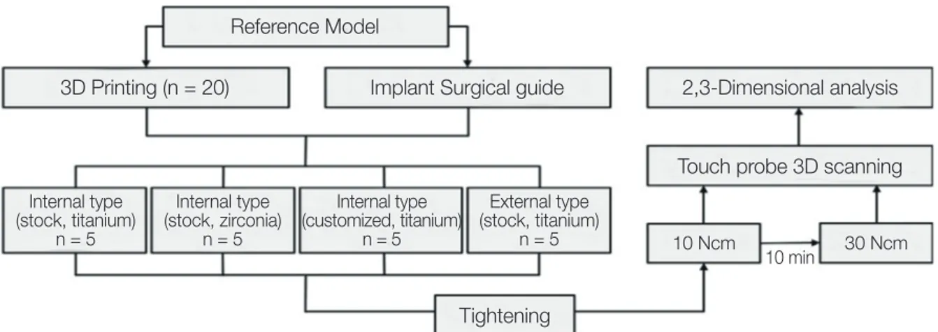
This study involved the following processes. First, working models were fabricated by using a 3D printer, then implants were placed and tightening torques were added at 10 and 30 N·cm with a contact scanner. These were scanned; then, 2D and 3D analyses were conducted (Fig. 1).
To determine appropriate sample size, a pilot experi- ment was conducted three times; for each abutment, a sam- ple size of five was calculated by using power analysis soft- ware (G*Power v3.1.9.2, Heinrich-Heine-University, Düsseldorf, Germany) (actual power = 100%, power = 99%, α = .05).
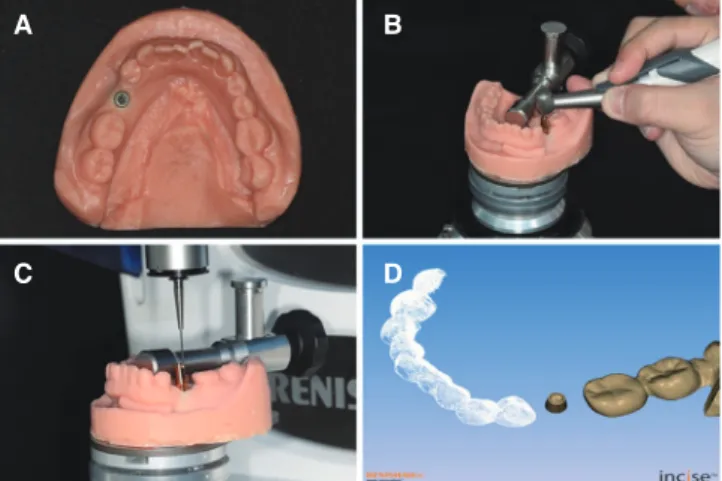
For an in vitro study, models missing mandibular left sec- ond premolars were scanned with an oral scanner (Aegis PO, Digital Dentistry Solution, Seoul, Korea) to acquire ste- reolithography (STL) files. Then, 20 models were produced in 16-µm layers by using a 3D printer (ZENITH, Dentis, Daegu, Korea). To prevent model abrasion by the contact scanner, resin was selected as the material for the model (ZMD-1000B, ZMD0171208B02, ZENITH). In addition, implants were placed in the same position in each model by using a surgical guide designed for placing implants in the mandibular left second premolar. External Fixture (EF4510, 171128A0650-01, AnyOne, MegaGen, Gyeongsan, Korea) and Internal Fixture (IF4510, 171027A0021-01, AnyOne, MegaGen, Gyeongsan, Korea) were used as implant fixtures (Ø 4.5, L = 10 mm) (Fig. 2A). In addition, implants were placed after bonding cyanoacrylate adhesive (Permabond
Fig. 1. Experimental design for evaluating axial displacement.
Reference Model
2,3-Dimensional analysis 3D Printing (n = 20) Implant Surgical guide
Touch probe 3D scanning
10 Ncm 30 Ncm
10 min Tightening
Internal type (stock, titanium)
n = 5
Internal type (stock, zirconia)
n = 5
Internal type (customized, titanium)
n = 5
External type (stock, titanium)
n = 5
910, Permabond LLC, Pottstown, PA, USA) was applied to imitate osseointegration (Fig. 3A).27
In this study, to examine axial displacement according to the type of implant-abutment connection, three INT-type abutments and one EXT-type abutment were prepared (Fig.
2B). Two of the three INT types used titanium abutment (EP4535H, 170703A0203-01, EZ Post, MegaGen, Gyeongsan, Korea) (Internal Stock, IS group) and zirconia abutment (GSZAS4535WH, PGA17F350, ZioCera, Osstem, Seoul, Korea) (Internal Zirconia, IZ group). The other INT type was a customized abutment designed by using computer- aided design software (Delta9, Daesung, Seoul, Korea). The design files were produced by milling the entire abutment, including the abutment connection, with a titanium round bar (KL31-213073, 3212209, KJ Meditech, Gwangju, Korea) in a high-precision computer-controlled milling machine (SR-20RIII, Star Micronics, Nakayoshida, Japan) (Internal Customized, IC group). The EXT-type titanium abutment (RCH538, 171120A0462-01, EZ Post, MegaGen, Gyeongsan, Korea) (External Stock, ES group) was used.
First, corrections were made for the accuracy of an elec- tronic torque driver (iSD 900, NSK Inc., Kanuma, Japan), and the trueness and repetitive reproducibility of the torque value were tested by using a digital torque gauge (MGT-12, Mark-10 Corp, New York, NY, USA). The screw of the abutment was tightened at 10 N·cm to represent hand tight- ening; 10 min later, it was tightened at the manufacturers’
recommended torque value (30 N·cm) (Fig. 3B).
After tightening at 10 and 30 N·cm, the abutment and adjacent teeth were scanned by using a contact scanner (DS10, Renishaw plc, Gloucestershire, UK) (Fig. 3C) and the data were stored in STL format (Fig. 3D).
The contact scanner used in this study scanned adjacent teeth and abutments with a 0.5-mm diameter probe, gently touching and rising vertically at 200-µm intervals. For true- ness and reproducibility, the contact scanner was calibrated each time and 20 abutments were contact-scanned. The accuracy of the contact scanner according to the manufac- turer is 20 µm. The contact scanner was precisely analyzed before and after the axial displacement for excellent repeti-
tive reproducibility and no error in the optical characteris- tics of the object.
Two-dimensional and 3D analyses were conducted with 3D inspection software (Geomagic Control X, 2018.0.1, 3D Systems, Rock Hill, SC, USA) (Fig. 4). Two-dimensional analysis was used to view vertical displacement, and 3D analysis was used to evaluate the overall displacement of the abutment. First, the software retrieved the 10-N·cm and 30-N·cm STL files, and the 10-N·cm STL file was used as reference data (Fig. 4A, B). Adjacent teeth were also set, separate from the abutment (Fig. 4C), and only adjacent teeth were designated as having best-fit alignment (Fig. 4D).
Here, the sampling ratio was set to 100%. In 2D analysis, four planes were formed to measure displacement in the vertical direction (Fig. 4E), and two points were specified in the top portion of the abutment in each plane to calculate the difference in distance, for a total of eight points (Fig.
4F, G). In addition, in 3D analysis, all data points were cal- culated to observe the overall displacement of the abutment (Fig. 4H). Data points were calculated by using the root mean square (RMS) value, as follows:
where X1,i is the measurement point of i in the reference data, X2,i is the measurement point of i in the measurement data, and n refers to the number of all points measured in each analysis.
The RMS value shows deviation from 0 for two differ- ent sets of data. Therefore, a low RMS value shows a high degree of 3D consistency in the overlapped data.28 In addi- tion, 3D comparison was performed by using a color differ-
Fig. 2. (A) Internal and external implant fixtures. (B) Abutment groups, from left to right: Internal connection (INT) type abutment using titanium abutment (IS group);
INT-type abutment using zirconia abutment (IZ group);
Customized abutment (IC group); external connection type abutment using titanium abutment (ES group).
A B
Fig. 3. (A) Fabrication of a working model. (B) Screw tightening with an electronic torque driver. (C) Touch probe three-dimensional (3D) scanning after screw tightening. (D) Converting stereolithography data through touch probe 3D scanning.
A B
C D
ence map, with a range of ± 100 µm (20 color segments) and a permissible tolerance of ± 10 µm (green). This makes it impossible to apply the error of less than 10 µm in the color difference map so that only the axial displacement according to the tightening torque can be seen. The error of less than 10 µm may indicate scan error and other errors, not axial displacement according to the tightening torque.
All data were analyzed by using the Statistical Package for the Social Sciences (version 23.0, IBM, Chicago, IL, USA) (α = .05). First, the normal distribution of data was investigated by using a Shapiro-Wilk test. Equality of vari- ance was evaluated by using the Levene test for normal dis- tribution. To determine the difference according to the type of implant-abutment connection, one-way analysis of vari- ance (ANOVA) was conducted; as a post-test, differences among the groups were analyzed with Tukey’s honest signif- icant difference test. To compare overall displacement (3D) and vertical displacement (2D) of the abutment, the differ-
ence was also checked by using an independent t-test. Lastly, to examine the interaction effect of analysis methods (2D, 3D) and implant-abutment connection types (IS, IC, IZ, and ES), two-way ANOVA was conducted.
RESULTS
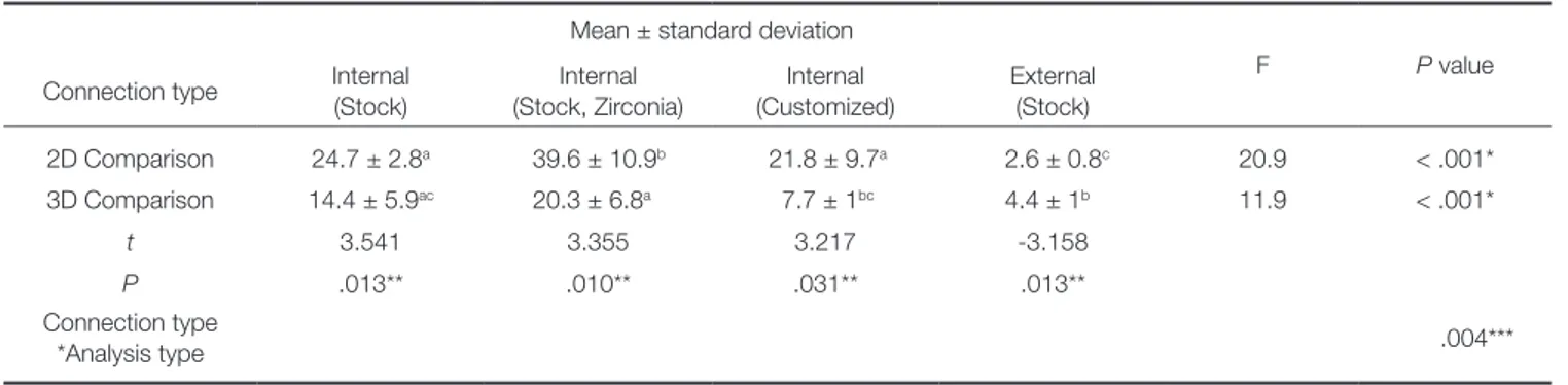
Two-dimensional and 3D analyses of the four types of abutments revealed significant differences according to the type of implant-abutment connection (P < .001) (Table 1).
In addition, the vertical displacement value (2D) of the abutment was larger than the overall displacement value (3D), and significant differences were observed among the four types of abutments (P < .05) (Table 1). An interaction effect was observed between analysis methods (2D, 3D) and among the implant-abutment connection types (IS, IC, IZ, and ES) (P = .004) (Table 1).
In 2D analysis, the IZ group (39.6 ± 10.9 µm) showed the
Table 1. Comparison of mean axial displacement among abutments (n = 5) Mean ± standard deviation
F P value
Connection type Internal (Stock)
Internal (Stock, Zirconia)
Internal (Customized)
External (Stock)
2D Comparison 24.7 ± 2.8a 39.6 ± 10.9b 21.8 ± 9.7a 2.6 ± 0.8c 20.9 < .001*
3D Comparison 14.4 ± 5.9ac 20.3 ± 6.8a 7.7 ± 1bc 4.4 ± 1b 11.9 < .001*
t 3.541 3.355 3.217 -3.158
P .013** .010** .031** .013**
Connection type
*Analysis type .004***
*P < .05; one-way analysis of variance, **P < .05; independent t-test, ***P < .05; two-way analysis of variance.
Mean values represented with same superscript lowercase letters (row) are not significantly different according to Tukey’s honest significant difference test (P < .05).
Fig. 4. Process of two-dimensional (2D) and three-dimensional (3D) analysis of the scanned abutment using 3D inspection software. (A) Abutment with 10-Ncm tightening. (B) Abutment with 30-Ncm tightening. (C) Splitting of reference data. (D) Process of best-fit alignment. (E) Plane settings for 2D analysis. (F) Specification of the point of the top portion of the abutment in the 2D plane. (G) Two-dimensional analysis with eight points. (H) Three-dimensional analysis of the abutment.
A B C D
E F G H
most displacement in the vertical direction, whereas the ES group (2.6 ± 0.8 µm) showed the least displacement in the vertical direction (Fig. 5). Similarly, in 3D analysis, the IZ group (20.3 ± 6.8 µm) showed the most displacement in the vertical direction, whereas the ES group (4.4 ± 1 µm) showed the least displacement in the vertical direction (Fig. 6).
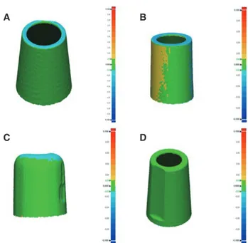
Fig. 7 shows that no 3D displacement of > 10 µm occurred in the ES group in the 3D analysis. In the IS and IC groups, displacement of > 10 µm occurred in the verti- cal direction, whereas no 3D displacement occurred in the horizontal direction on the axial plane of the abutment (Fig.
7). However, 3D displacement was noted in the horizontal direction on the axial plane of the abutment in the IZ group (20.3 ± 6.8 µm), demonstrating the greatest 3D dis- placement (Fig. 7).
DISCUSSION
There are several steps to making prosthetic implants, and axial displacement can occur at each stage.13,16,19,20 Among these steps, the greatest axial displacement is shown in the final implant prosthesis.13 Thus, in this study, axial displace- ments observed between hand tightening and screw tighten- ing at the recommended torque were evaluated, according to the implant-abutment connection type.
The null hypothesis in this study was as follows: no size difference exists in the displacement of the four types of abutments in 2D and 3D analyses. However, the results of this study rejected the null hypothesis (P < .001) (Table 1).
To compare 3D and 2D displacement of the abutment, overall displacement and vertical displacement were also assumed not to differ among the four types of abutments;
this assumption was also rejected (P < .05) (Table 1).
In the study by Dailey et al.,10 Yilmaz et al.,11 Siadat et al.,21 and Kim et al.,24 which found the difference in axial dis- placement according to the type of implant-abutment con- nection was similar to the result of this study (INT > ETX).
Because INT is less able to prevent vertical motion than EXT, vertical displacement occurs during screw tightening in INT.10-13 In this study, zirconia abutment (39.6 µm) showed greater axial displacement than titanium abutment (24.7 µm), but Gilbert et al.20 and Siadat et al.21 showed simi- lar axial displacements in both materials. Although the axial
Fig. 5. Comparison of mean two-dimensional displacement according to implant connection type.
2D Displacement (µm)
60
50
40
30
20
10
0 IS ISZ IC ES
Implant Connection Type
Internal (Stock) Internal (Stock, Zircona) Internal (Customized) External (Stock)
a
b
a
c
3D Displacement (µm)
30
20
10
0 IS ISZ IC ES
Implant Connection Type
Internal (Stock) Internal (Stock, Zircona) Internal (Customized) External (Stock) ac
a
bc
b
Fig. 6. Comparison of mean three-dimensional displacement (root mean square value) according to implant connection type.
Fig. 7. Comparison of the color maps of the four types of abutment through three-dimensional analysis. (A) Internal connection (INT) type abutment using titanium abutment (IS group). (B) INT-type abutment using zirconia abutment (IZ group). (C) Customized abutment (IC group). (D) External connection type abutment using titanium abutment (ES group).
A B
C D
displacement of the zirconia abutment has been large in this study, previous studies20,21 have shown that the effect of the type of implant-abutment connection is greater than the material.
Several studies reported axial displacement during screw tightening. Yilmaz et al.11 identified a significant difference between hand tightening and the torque wrench method.
Dailey10 measured axial displacement when using the recom- mended torque (25 N·cm) and a higher torque (45 N·cm);
average axial displacement was 50 µm at the recommended torque, and 89 µm at the higher torque. Gilbert20 measured axial displacement in nine types of abutments and found that axial displacement was 3 - 12 µm in the horizontal direction and 3 - 5 µm in the vertical direction. Rebeeah27 measured axial displacement in two types of implant sys- tems and found that the displacement did not exceed 14 µm. Several studies have reported varying displacement val- ues because of differences in experimental conditions and measurement methods. In the present study, the difference in axial displacement between hand tightening (10 N·cm) and tightening at the recommended torque (30 N·cm) was measured; axial displacement occurred regardless of the type of implant-abutment connection. Of the four types of abutments, the INT zirconia ready-made abutment (39.6 ± 10.9 µm) exhibited the most displacement in the vertical direction, whereas the EXT ready-made abutment (2.6 ± 0.8 µm) exhibited the least displacement in the vertical direction. This result confirms a statistically significant dif- ference based on the type of implant-abutment connection (INT, EXT) (P < .001) (Table 1). In addition, no significant differences were observed according to the manufacturing method (IS, IC) of the INT-type abutments, whereas a sta- tistically significant difference was observed in relation to the material of the connection (P < .001) (Table 1).
Regarding the methods of measuring axial displacement, direct distance has mainly been measured by using a micrometer10,13,19 or by imaging with a 3D digital image cor- relation technique.20,26,27 In the present study, abutments and adjacent teeth were scanned by using a contact scanner to reduce errors in optical characteristics resulting from the material of the abutment,29 as well as from the experiment- er’s method of measurement. In accordance with ISO 12836, the contact scanner was operated at an ambient tem- perature of 23 ± 2°C; a single operator who was skilled in the use of the contact scanner conducted the scanning of each abutment. Furthermore, Geomagic 3D inspection soft- ware was used for 2D and 3D analyses, as recommended in ISO 12836.
Although the accuracy of all existing scanners is not entirely reliable, many studies report the use of an optical scanner with a reference model of approximately 10 µm for accuracy evaluation, and assess the accuracy of intraoral and extraoral scanners based on reference data.30-34 Persson et al.35 compared accuracy and stability between a contact scanner and a laser scanner; a small error of < 10 µm was observed on the contact scanner. Moreover, the contact scanner was more accurate and stable, and could more effi-
ciently reproduce the abutment margin, compared with the laser scanner. Dimitrova36 measured repeatability by imaging the abutment with an optical scanner (8.2 µm) and a con- tact-type scanner (6.9 µm), reporting excellent repeatability on contact scanners. Therefore, in this study, we measured displacement by using a contact-type scanner, which can acquire measurement points and obtain accurate coordi- nates by touching the probe directly, for scanning metal and zirconia abutment.
This study revealed differences in axial displacement, according to analysis method and type of implant-abutment connection; however, the effect of the prosthesis fabrica- tion method and results in actual clinical practice were not investigated. Thus, in the future, it is necessary to produce prostheses for use in a specific type of implant-abutment connection and to conduct additional studies to evaluate their clinical effectiveness, such as the effect on actual occlusal contact with adjacent teeth.
CONCLUSION
In the limited results of this in vitro study, significant differ- ences were observed in axial displacement according to the type and material of implant-abutment connection. Because this axial displacement may affect occlusal contact with adjacent teeth and implant prostheses, when choosing an abutment, axial displacement according to the type of con- nection must be considered. In addition, because axial dis- placement occurs regardless of INT and EXT during tight- ening at the recommended torque (30 N·cm), in a manner that contrasts with hand tightening (10 N·cm), it is advisable to tighten the screw at the manufacturers’ recommended torque, rather than hand tightening to adjust the prosthesis.
ORCID
KeunBaDa Son https://orcid.org/0000-0002-3177-8005 Kyu-Bok Lee https://orcid.org/0000-0002-1838-7229 REFERENCES
1. Brånemark PI, Adell R, Breine U, Hansson BO, Lindström J, Ohlsson A. Intra-osseous anchorage of dental prostheses. I.
Experimental studies. Scand J Plast Reconstr Surg 1969;3:81- 100.
2. Brånemark PI. Osseointegration and its experimental back- ground. J Prosthet Dent 1983;50:399-410.
3. Brånemark PI, Svensson B, van Steenberghe D. Ten-year sur- vival rates of fixed prostheses on four or six implants ad mo- dum Brånemark in full edentulism. Clin Oral Implants Res 1995;6:227-31.
4. Sutter F, Weber HP, Sorensen J, Belser U. The new restorative concept of the ITI dental implant system: design and engi- neering. Int J Periodontic Restor Dent 1993;13:408-31.
5. Ugurel CS, Steiner M, Isik-Ozkol G, Kutay O, Kern M.
Mechanical resistance of screwless morse taper and screw-re- tained implant-abutment connections. Clin Oral Implants Res
2015;26:137-42.
6. Brånemark PI, Hansson BO, Adell R, Breine U, Lindström J, Hallén O, Ohman A. Osseointegrated implants in the treat- ment of the edentulous jaw. Experience from a 10-year peri- od. Scand J Plast Reconstr Surg Suppl 1977;16:1-132.
7. Norton MR. An in vitro evaluation of the strength of an in- ternal conical interface compared to a butt joint interface in implant design. Clin Oral Implants Res 1997;8:290-8.
8. Maeda Y, Satoh T, Sogo M. In vitro differences of stress con- centrations for internal and external hex implant-abutment connections: a short communication. J Oral Rehabil 2006;33:
75-8.
9. Schwarz MS. Mechanical complications of dental implants.
Clin Oral Implants Res 2000;11:156-8.
10. Dailey B, Jordan L, Blind O, Tavernier B. Axial displacement of abutments into implants and implant replicas, with the ta- pered cone-screw internal connection, as a function of tight- ening torque. Int J Oral Maxillofac Implants 2009;24:251-6.
11. Yilmaz B, Seidt JD, McGlumphy EA, Clelland NL. Displacement of screw-retained single crowns into implants with conical in- ternal connections. Int J Oral Maxillofac Implants 2013;28:
803-6.
12. Winkler S, Ring K, Ring JD, Boberick KG. Implant screw me- chanics and the settling effect: overview. J Oral Implantol 2003;29:242-5.
13. Lee JH, Kim DG, Park CJ, Cho LR. Axial displacements in external and internal implant-abutment connection. Clin Oral Implants Res 2014;25:e83-9.
14. Spector MR, Donovan TE, Nicholls JI. An evaluation of im- pression techniques for osseointegrated implants. J Prosthet Dent 1990;63:444-7.
15. Liu DY, Cader FN, Abduo J, Palamara J. Accuracy of differ- ent implant impression techniques: Evaluation of new tray design concept. J Prosthodont 2017 Dec 29. doi: 10.1111/jo- pr.12733. [Epub ahead of print].
16. Tan KB, Nicholls JI. The effect of 3 torque delivery systems on gold screw preload at the gold cylinder-abutment screw joint. Int J Oral Maxillofac Implants 2002;17:175-83.
17. Dellinges MA, Tebrock OC. A measurement of torque values obtained with hand-held drivers in a simulated clinical setting.
J Prosthodont 1993;2:212-4.
18. Kanawati A, Richards MW, Becker JJ, Monaco NE. Measurement of clinicians’ ability to hand torque dental implant compo- nents. J Oral Implantol 2009;35:185-8.
19. Moon SJ, Kim HJ, Son MK, Chung CH. Sinking and fit of abutment of locking taper implant system. J Adv Prosthodont 2009;1:97-101.
20. Gilbert AB, Yilmaz B, Seidt JD, McGlumphy EA, Clelland NL, Chien HH. Three-Dimensional Displacement of Nine Different Abutments for an Implant with an Internal Hexagon Platform. Int J Oral Maxillofac Implants 2015;30:
781-8.
21. Siadat H, Beyabanaki E, Mousavi N, Alikhasi M. Comparison of fit accuracy and torque maintenance of zirconia and titani- um abutments for internal tri-channel and external-hex im- plant connections. J Adv Prosthodont 2017;9:271-7.
22. Goodacre CJ, Kan JY, Rungcharassaeng K. Clinical complica-
tions of osseointegrated implants. J Prosthet Dent 1999;81:
537-52.
23. Tagger Green N, Machtei EE, Horwitz J, Peled M. Fracture of dental implants: literature review and report of a case.
Implant Dent 2002;11:137-43.
24. Kim KS, Lim YJ, Kim MJ, Kwon HB, Yang JH, Lee JB, Yim SH. Variation in the total lengths of abutment/implant as- semblies generated with a function of applied tightening torque in external and internal implant-abutment connection.
Clin Oral Implants Res 2011;22:834-9.
25. Shim HW, Yang BE. Long-term cumulative survival and me- chanical complications of single-tooth Ankylos Implants: fo- cus on the abutment neck fractures. J Adv Prosthodont 2015;
7:423-30.
26. Messias A, Rocha S, Calha N, Neto MA, Nicolau P, Guerra F.
Effect of intentional abutment disconnection on the micro- movements of the implant-abutment assembly: a 3D digital image correlation analysis. Clin Oral Implants Res 2017;28:9- 16.
27. Rebeeah HA, Yilmaz B, Seidt JD, McGlumphy E, Clelland N, Brantley W. Comparison of 3D displacements of screw-re- tained zirconia implant crowns into implants with different internal connections with respect to screw tightening. J Prosthet Dent 2018;119:132-7.
28. Schaefer O, Watts DC, Sigusch BW, Kuepper H, Guentsch A.
Marginal and internal fit of pressed lithium disilicate partial crowns in vitro: a three-dimensional analysis of accuracy and reproducibility. Dent Mater 2012;28:320-6.
29. Rudolph H, Luthardt RG, Walter MH. Computer-aided analy- sis of the influence of digitizing and surfacing on the accura- cy in dental CAD/CAM technology. Comput Biol Med 2007;
37:579-87.
30. Rhee YK, Huh YH, Cho LR, Park CJ. Comparison of intra- oral scanning and conventional impression techniques using 3-dimensional superimposition. J Adv Prosthodont 2015;7:
460-7.
31. Park JM. Comparative analysis on reproducibility among 5 in- traoral scanners: sectional analysis according to restoration type and preparation outline form. J Adv Prosthodont 2016;
8:354-62.
32. Park HN, Lim YJ, Yi WJ, Han JS, Lee SP. A comparison of the accuracy of intraoral scanners using an intraoral environ- ment simulator. J Adv Prosthodont 2018;10:58-64.
33. Hayama H, Fueki K, Wadachi J, Wakabayashi N. Trueness and precision of digital impressions obtained using an intra- oral scanner with different head size in the partially edentu- lous mandible. J Prosthodont Res 2018;62:347-52.
34. Patzelt SB, Emmanouilidi A, Stampf S, Strub JR, Att W.
Accuracy of full-arch scans using intraoral scanners. Clin Oral Investig 2014;18:1687-94.
35. Persson A, Andersson M, Oden A, Sandborgh-Englund G. A three-dimensional evaluation of a laser scanner and a touch- probe scanner. J Prosthet Dent 2006;95:194-200.
36. Dimitrova M. A 3D evaluation of the repeatability of accuracy in optical and contact scanners. Doctor’s Thesis, Cardiff Metropolitan University, Cardiff, Wales, UK; 2017. p. 1-36.