시간 동기화에 근거한 리모트 레이저 용접 시스템에서의 로봇과 스캐너 인터페이싱
김정중*, 이준우*, 이주장*, 권경업**, 강희신***, 서정***,⌧
*한국과학기술원, **(주)에스아이에스, ***한국기계연구원
Interface between Robot and Scanner for Remote Laser Welding System Based on Time Synchronization
Jeong-Jung Kim*, Joon-Woo Lee*, Ju-Jang Lee*, Kyung-Up Kwon**, Hee-Shin Kang*** and Jeong Suh***
*KAIST, **SIS Co., **KIMM
Abstract
Remote laser beam welding (RLW) has the benefits of high speed and high quality welding, especially as applied to automotive industry. RLW is designed in a way that end effecter and head of scanner move simultaneously, and require the compensation for the motion of end effecter in order to weld proper position.
In this paper, we show the algorithms of RLW that enable the end effecter to synchronize with scanner based on time. The proposed method consists of two algorithms. These algorithms make it possible for the moving end effecter to weld on desired place. The effectiveness of the algorithms is shown by experiments.
초 록
원격레이저 용접은(RLW)은 고속으로 고품질의 용접을 가능하게 하고 특히 자동차산업에 적용할 때 그 장점이 발휘된다. RLW은 로봇의 말단과 스캐너가 동시에 움직이도록 설계되는데 적합한 위치에 용접을 하기 위해서는 말단의 움직임에 대한 보상이 이루어져야 한다. 본 논문에서는 스캐너와 말단을 시간에 기반하여 동기화 하는 RLW을 위한 알고리즘을 보인다. 제안된 알고리즘은 두 개의 알고리즘으로 구성 되어 있고 본 알고리즘으로 움직이는 말단이 원하는 위치에 용접을 가능하게 한다. 제안된 알고리즘의 효용성은 실험을 통해 보인다.
Keywords: Remote welding system(리모트 용접 시스템), Industrial robot(산업용 로봇), Galvanometer scanner (갈바노 스캐너), Time synchronization(시간 동기화)1)
1. 서 론
A typical welding is conducted on a fixed place and this configuration limits the welding range.
Remote laser beam welding (RLW) has the benefits of high speed and high quality welding, especially as applied to automotive industry1,2. This study targets a system combined with robots that can increase welding range3-6. RLW is designed in a way that
투고일 : 2013년 3월 12일 심사완료일 : 2013년 3월 18일 게재승인일 : 2013년 3월 21일
교신저자 : 서정 ⌧ [email protected]
end effecter and head of scanner move simultaneously, and require the compensation for the motion of end effecter in order to weld proper position.
In this paper, we show the algorithm of RLW that enable the end effecter to synchronize with scanner based on time. The proposed method consists of two algorithms: (1) a scanner-speed modification algorithm aimed at the compensation for the move of the end effecter. (2) a welding-time calculation algorithm for start time of trajectory. These algorithms make it possible for the moving end effecter to weld on desired place. All input variables
necessary for the each algorithm are five items including trajectory of the end effecter, trajectories of welding points, robot speed, welding speed and welding starting time.
The proposed algorithms are described in Section 2, experimental result and discussion are followed in Section 3, and conclusion is shown in Section 4.
2. Algorithm Description
2.1 System description
Fig. 1 illustrates the system used in the paper.
Fig. 1 Target system where both scanner and laser generator are attached to the end effecter of industrial robot and the welding process can be conducted while the end effecter is moving.
The scanner and the laser generator are attached to the end effector of the industrial robot. This scanner is also connected to a control board in PC, and serves as locating the laser to desired positions while the PC controls the welding position, welding speed, and delays values. Welding process can be relatively easy when the end effecter is not moving, but in case the end effecter is moving, relative speed should be taken into account for welding on accurate position.
2.2 Algorithm for welding speed modification
With the welding speed modification algorithm based on the system with scanner and robot, values such as trajectories of end effecter and of welding are given in advance. The welding points and the relative speed of end effecter are calculated by substituting the given values above. The resulting
values can make it successful to weld on preferred positions even when the end effecter is moving.
When the end effecter is moving, this algorithm modifies the welding speed and weld on appropriate trajectories. The inputs required for this algorithm are length Sw of welding trajectory, welding speed Vw, and end effecter speed Vr.
Assuming that the welding speed is constant in welding trajectory, the welding time Tw is calculated to be Sw/Vw. And since the duration for welding has the same value as that for movement of the end effecter, Tr equates to Tw. When the welding time is determined, the total step of trajectories, named TS, can be obtained after being divided by dt, a sampling time. The welding performed within the trajectory proceeds at a speed of Vw during Tw and TS steps. Welding is conducted based on the relation between variables including Tw, duration and Vw, speed and TS, stage. At a time t, the positions of the welding and the end effecter, WX(t), WY(t), RX(t), and RY(t) are calculated by the above relation. In a case when the end effecter moves, the relative welding position needs to be considered for accurate welding along the trajectory.
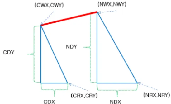
The current relative position between the weld and the end effecter, on X and Y axis are expressed by CDX = CWX – CRX and CDY = CWY – CRY, where CWX, CWY, CRX, CRY are WX(t), WY(t), RX(t), and RY(t) respectively.
The next relative position between the weld and the end effecter, on X and Y axis are expressed by NDX = NWX – NRX and NDY = NWY – NRY, where NWX, NWY, and NRX, and NRY are WX (t+dt), WY(t+dt), RX(t+dt), and RY(t+dt) respectively.
Fig. 2 The geometrical relations between variables while a robot is moving.
The geometrical relations between variables with end effecter moving. The solid line from the point (CWX, CWY) to (NWX, NWY) is welded during sampling time dt. The distance of the straight line DISTg is calculated using the formula, DISTg = sqrt((NDX - CDX)2 + (NDY–CDY)2). During the sampling time dt, the welding is conducted at a constant speed. The welding speed Vg is calculated by the formula Vg=DISTg/dt. The welding is conducted from the point (CDX, CDY) to (NDX, NDY) with the calculated welding speed Vg
during sampling time dt. The speed compensates the speed of the moving end effector and a welding can be conducted on a proper position.
2.3 Algorithm for welding starting time computation
The start times for each welding trajectory are computed when the values including the trajectory of the end effecter, welding trajectories, robot speed and welding speed are given. This algorithm assumes that welding process initiates at a point that is closest to the center of the welding trajectory.
The welding start point is defined as Pwst, which of the relation is shown in the Fig. 3.
Fig. 3 Computation of welding start time. Both welding start position and welding time at welding trajectory are calculated using the given values of trajectories of end effector and welding.
The values of each welding start time, Twst, can be gathered to make time schedule, which includes total processing time, called Ttotal. Ttotal
is calculated by dividing Str by Vr, Str is the total length of robot trajectory and Vr is the robot speed. Twst is calculated by dividing Lwst, by Vr.. Lwst, is the length ranging from the initial position of the end effector to Pwst. The example of the time schedule is shown in Fig. 4.
Fig. 4 Time schedule for welding on each welding tra- jectories.
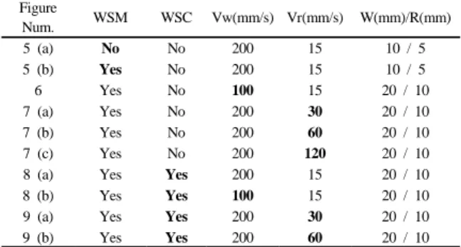
Table 1 Summary of experimental conditions
Figure
Num. WSM WSC Vw(mm/s) Vr(mm/s) W(mm)/R(mm)
5 (a) No No 200 15 10 / 5
5 (b) Yes No 200 15 10 / 5
6 Yes No 100 15 20 / 10
7 (a) Yes No 200 30 20 / 10
7 (b) Yes No 200 60 20 / 10
7 (c) Yes No 200 120 20 / 10
8 (a) Yes Yes 200 15 20 / 10
8 (b) Yes Yes 100 15 20 / 10
9 (a) Yes Yes 200 30 20 / 10
9 (b) Yes Yes 200 60 20 / 10
The timer starts when the end effector begins to move. When the time is reached to each Twst, then relative welding points are calculated based on the robot speed and welding speed and the welding process is conducted during Tw.
3. Experiment
Two major experiments were chosen to verify the proposed algorithm. Table 1 summarizes experimental conditions. Conditions from the first row to sixth row are for first experiment and from the seventh row to last row are for second experiment. The notations WSM, WSC, W and R represent welding speed modification algorithm, welding starting time computation algorithm, width of a rectangle, radius of circle, respectively.
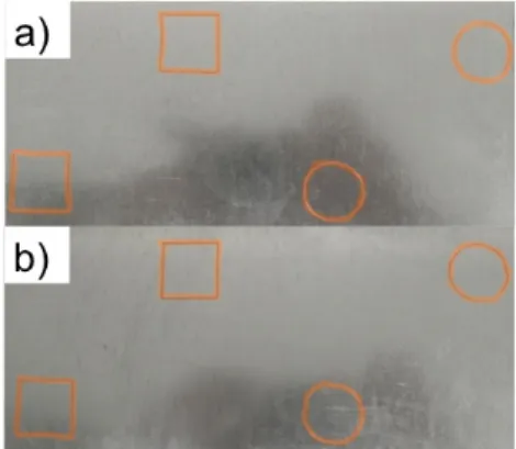
The first experiment is to test a welding speed modification algorithm. This experiment consists of welding the shapes of rectangle and circle, and welding at a speed of end effector and at various welding speeds. As shown in the Fig. 5, the proposed algorithm successfully welded on desired trajectory, but the result without this algorithm failed to weld on desired trajectory.
The reason is that proposed algorithm compensated the speed of the moving end-effector and welded on proper positions.
The results when the welding speed is decreased is shown in Fig. 6 and speed of the end effector is varied is shown in Fig. 7.
Fig. 5 Experiment results of welding-speed modification algorithm. (a) the welding before applying the speed modification algorithm (b) the welding after applying the speed modification algorithm.
Fig. 6 Experiment results of speed modification algorithm when applying various welding speeds, at a welding speed of 100 mm/s.
Fig. 7 Experiment results of speed modification algorithm when applying various speeds of end effecter, (a) 30mm/s (b) 60mm/s (c) 120mm/s.
Even though the proposed algorithm is applied to the system, mismatch was found when the welding speed was decreased and end effector speed was increased as shown in the Fig. 6 and Fig. 7. In our experimental setting, the visible mismatch was found when the speed of the end effector was reached the 15% of the welding speed. It was result from the existence of time delay between PC and scanner controller and
control accuracy of the end-effector and scanner.
The importance of degree of mismatch depends on applications. The mismatch should be reduced for a high accuracy application. The mismatch can be solved to a certain degree by adjusting the parameter of the scanner which includes:
jump delay, welding delay, laser on-and-off time delay and improving the accuracy of the controllers.
The second experiment is to test welding-start time computation algorithm. The objective of this experiment is to start to weld the shapes of rectangle and circle at a proper time, using the given values such as end effector speed and various welding speeds.
Fig. 8 Experiment results of start time computation algorithm at various welding speeds. (a)200mm/s (b)100mm/s.
Fig. 9 Experiment results of start time computation algorithm at various speeds of end effector.
(a)30mm/s (b)60mm/s.
The results in Fig. 8 show the comparison between welded shapes depending on various welding speeds and Fig. 9 show the comparison between welded shapes depending on various speeds of end effecter.
As shown in the Fig.8 and Fig. 9, the proposed
algorithm welded the shapes of rectangle and circle at a proper time and mismatches were detected when welding speed was decreased and speed of the end effector was increased. The reason for the mismatch is same as in the first experiment.
The mismatch can also be solved to a certain degree by adjusting the parameter of the scanner and improving the accuracy of the controllers.
4. Conclusions
In this paper, we have shown RWL that is operated by two algorithms where the end effector of a robot and the scanner move simultaneously.
The proposed algorithms were verified through several experiments and turned out to be capable of welding on the desirable trajectories even when the end effector was moving. We expect the method to be applied to more complex and high dimensional system.
References
1) M. Grupp, T. Seefeld and F. Vollertsen, “Laser Beam Welding with Scanner,” Proc. of the Sec.
Int. WLT-Conf. on Lasers in Manuf., Munich, Germany, 2003.
2) G. Tsoukantas, G. Chryssolouris, “Theoretical and Experimental Analysis of the Remote Welding Process on thin, Lap-joined AISI 304 Sheets,”
Int. J. Adv. Manuf. Technol. Vol. 35, No. 9-10, pp. 880-894, 2008.
3) J. Stemmann and R. Zunke, Oper. “Robot Task Planning for Laser Remote Welding”, Oper. Res.
Proc., Vol. 2005, pp. 729-734, 2008.
4) J. Hatwig, G. Reinhart, and M. F. Zaeh, “Auto- mated Task Planning for Industrial Robots and Laser Scanners for Remote Laser Beam Welding and Cutting”, Prod. Eng. Res. Devel. , Vol. No.
4, pp. 327-332, 2010.
5) M. F. Zaeh, J. Hatwig, J. Musiol, O. Roesch and G. Reinhart, “Analysis of the Accuracy of Industrial Robots and Laser Scanners for Remote Laser
Beam Welding and Cutting”, Proc. of the 41st Int. Symp. on and 2010 6th German Conf. on Rob. (ROBOTIK), pp. 751-758, 2010.
6) H.-S. Kang, J. Suh, S. J. Kwak, “Welding on the Fly by using Laser scanner and Robot”, Proc.
of the 11th Int. Conf. on Con., Aut. and Sys., pp. 1688-1691, 2011.