학술논문 지상무기 부문
대용량 포미장치 피로시험기의 충격 거동 모델링
A Study of Dynamic Impact Models for Pile-Driver Breech Fatigue Testing System
조 창 기* 차 기 업*
Chang-Ki Cho Ki-Up Cha
Abstract
This paper presents the modeling and validation of a pile-driver breech fatigue testing system model to replicate actual high pressure in a large caliber gun barrel. A hysteresis damping function was incorporated in the nonlinear impact force model. Test of real pile-driver breech fatigue testing system had been performed for model validation.
Comparison of the experimental result and model simulation during impact were made. Numerical studies were performed to evaluate how the actual chamber pressure pattern in the live firing of gun barrel was affected by parameters' variation. Some of the parameters simulated included input velocity, damping coefficient and stiffness.
As a result, a variety of actual chamber pressure pattern could be reproduced and cotrolled through current simulation model.
Keywords : Breech Fatigue Testing System, Impact Force Modeling, Contact Stiffness, Hysteresis Damping
1. Introduction
In many mechanical systems, typical dynamic loading is expressed by the form of impulsive force. The Impact phenomenon is the most common type of dynamic loading conditions that give rise to impulsive forces. The impact is characterized by abrupt changes in the values of system variables. Therefore, some appropriate contact- impact force model must be introduced in order to
†2010년 3월 30일 접수~2010년 7월 12일 게재승인
* 국방과학연구소(ADD)
책임저자 : 조창기([email protected])
simulate and design the impact behaviour in mechanical systems adequately.
In some cases, the estimation of the patterns and maximum values of contact forces for design or safety reasons are required.
Hunt and Crossley[1] showed that linear spring-damper model did not represent the physical nature of energy transfer process and proposed the contact forces by the Hertz force-displacement law. They estimated the energy dissipated due to impact was obtained in terms of a nonlinear damping force that was proportional to the nth power of elastic indentation between the contact surfaces. However, this analysis is confined to two
bodies impacting at low velocities. Khulief and Shabana[2] developed a spring-dashpot model with a nonlinear stiffness and a nonlinear damping in order to account for the energy loss due to impact. Yigit et al.[3]
showed that a spring-dashpot model with nonlinear stiffness and damping law gives good results for the impact response of a radially rotating beam. The disadvantage of the spring-dashpot model is that the parameters of a damping model are difficult to obtain.
Generally, the coefficient of restitution together with a simplified lumped parameter model of the system have to be used to obtain the damping parameters. Lankarani and Nikravesh[4] extended a contact force model with hysteresis damping to impact in multibody systems.
Schwab et al.[5] investigated the dynamic response of mechanisms and machines affected by revolute joint clearance. They showed the procedure to estimate the maximum contact force during impact. Anping Guo et al.[6] estimated the restitution coefficient straightforwardly from impact force history.
For many years, the determination of safe service life for large caliber gun has been experimentally verified using hydraulic pressurization to economically replicate the firing pressures of large caliber gun without firing live ammunition. Hydraulic simulation of breech assemblies has included a dynamic pressure pulse for increased fidelity of the experimental simulation. In particular, a new gun system will require tens of thousands of cycles to determine fatigue life. However, it is complicate to simulate the impulsive force such as the chamber pressure of large caliber gun barrel in order to estimate the endurance life of gun barrel or breech mechanism.
Up to now, most researches are restricted within the impact analysis between elastic bodies and structures.
Few analyses of the pile driver impact to replicate high pressure in a large caliber gun barrel have been published by Kathe[7] and Berggren.[8] The purpose of this paper is to investigate the dynamic characteristics of the pile driver fatigue tester regarding how it reproduce actual chamber pressure.
2. A Continuous Contact Force Model When two solid bodies are in contact, indentation occurs in the local contact zone subjected to the contact force. In the analysis of continuous contact force model, it is very important to determine the relationship between the contact force and the relative indentation between the two bodies.
The impact is generally considered to occur in two phases separately, the indentation phase and the restitution phase. The restitution phase starts at the instant of maximum indentation and lasts until the two bodies separate completely.
The basic contact force model starts from the impact of two spheres. If the contact area between the colliding objects is assumed to be small, the simplest and the best known contact force model between two spheres of isotropic materials is the non-linear Hertz law based on the theory of elasticity.[1] It is represented as a polynomial dependence of the contact force on the indentation :
≤ (1) where the generalized stiffness constant depends on the material properties and the radii of the spheres and
is the local relative normal indentation between the surfaces of the two spheres. So the indentation is computed as the difference between the displacements at contact point of two spheres. Therefore, the condition
> 0 represents that there is actual indentation, while the complementary condition ≤0 states that the two spheres are not in contact. For the frictionless Hertzian contact between two spheres, the exponent is set to 1.5 for metallic surfaces and the stiffness parameter [4]
is given by:
(2)
where the material parameters are
(3)
with radius , Poisson’s ratio and Young’s modulus associated with each sphere.
The most complicated part of impact modeling is the process of energy transfer. Because the original Hertzian contact force model does not represent the energy dissipation, it cannot cover both of the two phases, compression and restitution, during impact.
The contact force models given by equations (1) and (2) are only valid for colliding bodies with circular contact areas. Some authors suggest the using of the more general force-displacement relation given by equation (4) but with a lower exponent, , between 1 and 1.5.
Therefore, the Hertz relation along with the modification to explain the energy dissipation in the form of internal damping can be adopted for modeling contact forces in vibroimpact[1] and in a multibody system.[4,5] Under the hypothesis that the contact surface is small, Hunt and Crossley proposed the following form for the contact force :
≤ (4)
(5)
where is the relative indentation depth, is the relative indentation velocity, and and are defined as above. The parameter is called a nonlinear damping coefficient or a hysteresis form for the damping coefficient and is called the hysteresis damping factor.
Similarly to equation (1), the value of the exponent depends only the local geometry around the contact surface. The force model of equation (4) includes both an elastic component and a dissipative term , and this dissipative term depends on both and , and is zero for zero indentation.
The so-called hysteresis damping factor can be
estimated from a comparison of the energy loss at a central impact of two spheres with coefficient of restitution after one hysteresis loop, yielding
(6)
with , the indentation velocity just before impact, i.e., the initial impact velocity.
This model is expressed as,
(7)
On the other hand, Anping Guo et al.[6] estimated the coefficient of restitution straightforwardly from impact force history as follows:
def
(8)
3. A Mathematical Model
3.1 Description of the existing system The general view of pile driver breech fatigue system [PDBFS] used to test the breech components are represented in Fig. 1. PDBFS is composed of a hammer, a loading piston, a seal assembly, an hydraulic oil and a filler bar, the stub tube, the breech assembly, a fixed receiver ring and the main frame.
The sectional view of impact force transfer mechanism [IFTM] showing the basic structural elements of this system is described in Fig. 2.
Hammer drops vertically from fixed height and impacts on the loading piston. The loading piston transfers the impacted force to the test object connected to the main frame through a seal assembly, a filler bar and hydraulic oil.
Fig. 1. General view of PDBFS
Fig. 2. Sectional view of IFTM
3.2 Equations of motion
Adopting a very complex model may be considered as poor a judgment as an adopting an oversimplified model because the energy and time required to study complex models is wasteful. A reasonably simplified model makes the analysis much simpler as the result of reducing the number of variables and the complexity of the resulting equations of motion.
Therefore, a mathematical model for PDBFS is represented by a simplified model which has equivalent inertia, damping, and stiffness characteristics. The fundamental case of a Hertzian contact law and a non-
linear damping law in relation to the modeling of the impact system are introduced.
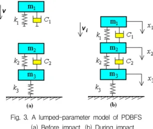
Because the interest is focused only on the reproduction of the magnitude and pattern of oil pressure exerted on the test specimen during impact, a simpler model can be used. Fig. 3. shows a three degree of freedom lumped model for PDBFS.
Fig. 3. A lumped-parameter model of PDBFS (a) Before impact, (b) During impact
It is known that the linear spring-damper model does not represent the physical nature of energy transfer process, therefore a hysteresis damping function, which represents the dissipated energy during the impact, is introduced in the impact force model. Hertzian modified contact model on the impact only between hammer and loading piston is considered, but not considered in the contact between the loading piston and the seal assembly.
Applying Newton’s 2nd law, ∑ , to each mass in Fig. 3, the governed equations are derived from the free-body diagram as the following three coupled equations:
(9)
for
where is the lumped mass of the hammer, is the equivalent mass of the loading piston and seal assembly and is the equivalent mass of the fixed receiver ring, the stub tube and the breech assembly connected to the main frame, and their corresponding displacements are expressed as , and , respectively. In this model, the coefficient represents the nonlinear contact stiffness from Hertzian contact model, , = 1.5, where is the relative indentation of the bodies at the contact points. It means the difference between the displacement of hammer, , and the displacement of loading piston, . The coefficient represents the bulk modulus of hydraulic oil. The coefficient represents the equivalent stiffness of the joints between stub tube including breech assembly and fixed receiver ring. In this model, the damping coefficient represents a nonlinear damping coefficient and is proposed to account for the energy loss during impact. The damping coefficient is introduced to account for the dissipation of energy as the result of friction of seal assembly.
The nonlinear differential equations (9) are solved for the initial conditions:
(10)
However, the validity of model in representing the real system depends on how to tune well the inertia, damping and stiffness characteristics of the system.
4. Model Simulation and Validation 4.1 Model simulation
The solution of equation (9) is obtained numerically using the 4th-order Runge-Kutta method. To solve the equation (9), the Runge-Kutta method is implemented by a windows supported MATLAB package. The calculation algorithm can be described as follows: (a) Assign the
initial conditions and the total iteration time for calculation. (b) Assign the parameter values of , ,
, , , , , , , and . (c) Compute the state variables using the Runge-Kutta method. These steps were iterated until the final time is satisfied.
4.1.1 Determination of input parameters Since we are interested in the shape of pressure, it is important to select the contact force model correctly.
But major difficulty in the present design is how to define indefinite stiffness and damping parameters. At first, the estimated values in conjunction with the input parameters such as the stiffness, the damping coefficient and the damping frictional coefficient were used because the exact values were unknown and later were compared to the experimental values of the system.
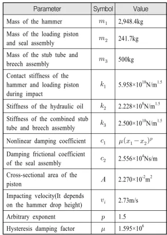
All the parameters used for the calculations in this model are listed in Table 1.
Table 1. Parameters for PDBFS from Fig. 3
Parameter Symbol Value
Mass of the hammer 2,948.4kg Mass of the loading piston
and seal assembly 241.7kg Mass of the stub tube and
breech assembly 500kg
Contact stiffness of the hammer and loading piston during impact
5.958×10¹⁰N/m1.5
Stiffness of the hydraulic oil 2.228×10⁸N/m1.5 Stiffness of the combined stub
tube and breech assembly 2.500×10¹⁰N/m1.5 Nonlinear damping coefficient Damping frictional coefficient
of the seal assembly 2.556×10⁴Ns/m Cross-sectional area of the
piston 2.270×10⁻²m2
Impacting velocity(It depends
on the hammer drop height) 2.73m/s
Arbitrary exponent 1.5
Hysteresis damping factor 1.595×10⁶
First, the stiffness parameter of contact area needs to be determined. It is assumed that the contact area keeps circular contact and is much smaller than the radii of curvature of the hammer and the loading piston. The materials in contact are steels with Young’s modulus
= 2.1 × 10¹¹N/m2, Poisson’s ratio = 0.3. The coefficient of restitution is assumed to be = 0.95. The radii of curvature of the hammer and the loading piston are 300mm.[8] Therefore the stiffness parameter can be calculated from equation (2) to be 5.958 × 10¹⁰N/m1.5. Hysteresis damping factor can be calculated from equation (6) to be 1.595 × 10⁹. But here because it is value by calculation, not by experiment, a little lower value 5.958 × 10⁶ is used.
Second, the stiffness represents the characteristics of hydraulic oil dynamically connected to the stub tube and the breech assembly. It can be replaced by the bulk modulus of hydraulic fluid because the fluid is incompressible in general. Although bulk modulus of the oil (water-glycol) is 2.189 × 10⁹N/m1.5, here it is assumed to be 2.228 × 10⁸N/m1.5.
Especially, an impact velocity, (m/s), of the hammer just before impact is calculated from =
, which depends on the drop height(h).
4.1.2 Simulation
In the impact force history, the maximum force occurs when the indentation of the loading piston at the contact is at a maximum, i.e., the displacement of the hammer is at a maximum.
During the duration of contact, the impact force,
, is always positive. Once it becomes negative in the progress of computation, the contact phase is complete.
Fig. 4 shows the impact force history of hammer exerted on the loading piston during impact at impact velocity = 2.73m/s using currently developed model for PDBFS. Here is indented impulse and is final impulse.
Since the loading piston is initially at rest, the coefficient of restitution, , can be estimated straightforwardly from Fig. 4. The coefficient of the
restitution based on the equation (8) in this example ranges from 0.90 to 0.95.
0 2 4 6 8 10 12 14
0 1 2 3 4 5 6 7
X Pf Pi
Restitution Indentation
Maximum Force X
Force (x107kN)
Time (ms) Hammer
Fig. 4. Impact force history of hammer exerted on the loading piston during impact at impact velocity
= 2.73m/s. Parameters , , , , , are the same in Table 1
4.2 Model validation
The simulation model has been validated by comparing the pressure results obtained by the simulation with the experimental results of the real system(06 Vulcan PDBFS) conducted by Benet Labs.
4.2.1 Experimental results
The impact experiment was performed by using the 06 Vulcan PDBFS in order to validate the simulation model. The hammer is dropped freely on the loading piston through the guide-rail from the required height as shown in Fig. 1. It has the mass = 2,948.4kg. It is released from a vertical height = 0.254m above the loading piston and the initial impact velocity of the hammer depends on the height().
The oil pressure in chamber was picked up at three locations, Kistler pressure sensors at two locations and HAT gage at one location of the oil chamber. HAT gage is made of strain gages and calibrated by Benet Labs. The oil pressure was measured with Kistler pressure sensor (Type 6203). A Nicolet Odyssey data
recorder was used to record all data. A dual mode amplifier (Type 5010, Kistler) and a signal conditioning amplifier (Type 2310, Instruments Division) were used.
4.2.2 Comparison
In order to validate this method, the numerical result of PDBFS with nonlinear contact force model needs to be compared with the experimental one. Fig. 5 shows the comparison of numerical result and experimental one.
It shows the good correspondence between both results.
Parameters(, , , , , , ) in simulation are the same in Table 1.
0 2 4 6 8 10 12 14
0 20 40 60 80 100
Pressure (MPa)
Time (ms)
Simulation Experiment
Fig. 5. Comparison of pressure exerted on the breech assembly
5. Discussion
Fig. 6 shows the pressure versus time history at oil chamber during impact for different impact velocities in the contact force model with nonlinear stiffness and nonlinear damping. It means the pressure exerted on the stud tube through the oil during impact.
Fig. 7 shows the displacement histories of the loading piston and seal assembly according to drop velocities . Its displacement increases as the velocity increases.
Other parameters are the same in Table 1.
Fig. 8 shows the effects of the variation of damping coefficient during impact.
0 2 4 6 8 10 12 14
0 50 100 150 200
Pressure (MPa)
Time (ms)
v=1.87 m/s v=2.73 m/s v=4.23 m/s v=5.50 m/s
Fig. 6. Pressure vs. time history at oil chamber during impact for different impact velocities
0 5 10 15 20
0.000 0.005 0.010 0.015 0.020 0.025
Displacement (m)
Time (ms)
v=1.87 m/s v=2.73 m/s v=4.23 m/s v=5.50 m/s
Fig. 7. Displacement histories of the loading piston and seal assembly during impact
0 5 10 15 20
0 50 100 150 200
Pressure (MPa)
Time (ms)
c2=2.556E3 Ns/m c2=2.556E4 Ns/m c2=2.556E5 Ns/m c2=2.556E6 Ns/m
Fig. 8. Effects of variation during impact
Fig. 9 shows the pressure time histories exerted on the loading piston through the oil in the chamber during impact with = 2.73m/s. It is found that the pressure increases and the duration time shortens as the stiffness
increases from Fig 9.
0 5 10 15 20
0 50 100 150 200
Pressure (MPa)
Time (ms)
k2=0.922E8 N/m1.5 k2=2.228E8 N/m1.5 k2=5.228E8 N/m1.5 k2=8.228E8 N/m1.5
Fig. 9. Pressure vs. time histories exerted on the stud tube according to variation
6. Conclusion
In this study, the impact behavior of the impact pile driver breech fatigue system was investigated using a lumped parameter approach with a simple nonlinear spring-mass-damper model.
For the experimental investigation Kistler pressure sensor was used for the measurement of oil pressure pattern exerted on the breech assembly. Simulation result of nonlinear contact force model showed the good correspondence with the experimental result of real system, 06 Vulcan PDBFS.
Magnitude of pressure pattern was governed by impact velocity. Pressure duration time was controlled by the damping coefficient of seal assembly, , which accounts for the energy dissipation as the result of friction.
However, the stiffness of the hydraulic oil, , controlled both the magnitude and the duration time.
Therefore it was shown that the actual chamber pressure pattern in the live firing gun tube during
impact could be reproduced by current simulation model.
The equivalent mass of the loading piston and seal assembly, , needs to be split into several separated masses in order to obtain more detailed information about transferring process of impact force.
Acknowledgement
This work has been done under the Engineer and Scientist Exchange Program at Benet Laboratories of US Army ARDEC during the 2006~2007 year. In particular we acknowledge Dr. Eric L Kathe and Mr. Robert W Berggren.
References
[1] Hunt, K. H. and Crossley, F. R. E., “Coefficient of Restitution Interpreted as Damping in Vibroimpact”, ASME Journal of Applied Mechanics, pp. 440~445, June 1975.
[2] Khulief, Y. A. and Shabana, A. A., “A Continuous Force Model for the Impact Analysis of Flexible Multibody Systems”, Mech. Mach. Theory, Vol. 22, No. 3, pp. 213~224, 1987.
[3] Yigit, A. S., Ulsoy, A. G. and Scott, R. A., “Spring -Dashpot Models for the Dynamics of a Radially Rotating Beam with Impact”, Journal of Sound and Vibration, Vol. 142, No. 3, pp. 515~525, 1990.
[4] Lankarani, N. M. and Nikravesh, P. E., “Continuous Contact Force Models for Impact Analysis in Multibody Systems”, Nonlinear Dynamics 5, pp. 193
~207, 1994.
[5] Schwab, A. L., Meijaard, J. P. and Meijers, P., “A Comparison of Revolute Joint Clearance Models in the Dynamic Analysis of Rigid and Elastic Mechanical Systems”, Mechanism and Machine Theory 37, pp. 895~913, 2002.
[6] Anping Guo and Steve Batzer, “Substructure Analysis of a Flexible System Contact-Impact Event”, Journal of Vibration and Acoustics, Vol. 126, pp. 126~131, January 2004.
[7] Eric Kathe et al., “Using a Six Ton Pile Driver to Mimic Firing Pressures of Large Caliber Cannon- Softly”, The 76th Shock & Vibration Symposium, November 2005.
[8] Berggren, R. W., “BFSIM Analysis and Validation”, ARDEC Modeling and Simulation Forum, October 2006.