145
단잔광 냉음극관을 이용한 잔상없는 TFT-LCD에 관한 연구
최대섭
*, 신호철
**Study of Blurring Free TFT-LCD Using Short Persistance Cold Cathode Fluorescent Lamp in Blinking Backlight Driving
Dae-Seub Choi
*, Ho-Chul Sin
**요 약
최근의 TV용 TFT-LCD에서는 동화상에서의 잔상발생을 줄이는 것이 중요한 기술적 요구사항이 되었다. Single-LVDS 신호체계에 서 3D를 대응하기 위한 Quad Signal Package 까지 진화하면서 보다 빠른 신호를 정해진 시간안에 처리해야 하는 문제가 발생하고 있으며, 이러한 특성을 구현하기 위해서 잔상효과가 없는 Backlight에 대한 연구가 활발히 진행되고 있다. 본 연구에서는 점멸방식의 Backlight 를 사용하여, 1Frame의 시간안에 이 동작이 가능하게 구현하는 것을 목표로 삼았으며, 광원으로는 기존의 냉음극관램프를 사용하였다. 통상 냉음극관램프는 주 발광파장대를 담당하는 녹색의 잔광시간이 길어서 위와 같은 특성을 구현하기에 어려움이 있 었으나, 본 연구에서는 단잔광 특성을 가지는 녹색 및 적색 형광체를 적용한 냉음극관램프를 적용하여, 1Video Frame의 시간안에 점멸동작이 가능한 백라이트를 제작하였으며, 이를 사용하여, 동화상에서 비약적인 잔상 해결 효과를 확인할 수 있었다.
Key Words : Motion Blur Free, Short Persistance CCFL, Backlight
ABSTRACT
In applying LCD to TV application, one of the most significant factors to be improved is image sticking on the moving picture. LCD is different from CRT in the sense that it’s continuous passive device, which holds images in entire frame period, while impulse type device generate image in very short time. To reduce image sticking problem related to hold typedisplay mode, we made an experiment to drive TN-LCD like CRT. We made articulate images by turn on-off backlight, and we realized the ratio of Back Light on-off time by counting between on time and off time for video signal input during 1 frame (16.7ms). Conventional CCFL (cold cathode fluorescent lamp) cannot follow fast on-off speed, so we evaluated new fluorescent substances of light source to improve residual light characteristic of CCFL. We realized articulate image generation similar to CRT by CCFL blinking drive and TN-LCD overdriving. As a result, reduced image sticking phenomenon was validated by naked eye and response time measurement.
※ 본 논문은 2011년도 서일대학 학술연구비에 의해 연구되었음
*서일대학교 전기과([email protected])
**삼일이엔씨
접수일자 : 2012년 12월 8일, 수정완료일자 : 2012년 12월 13일, 최종게재확정일자 : 2012년 12월 17일
I. Introduction
Recently, the demands of LCD (Liquid Crystal Display) for TV increase rapidly and image quality of LCD TV at the level of existing CRT is actively investigated [1-2].
One of the most necessary factors to adapt LCD for TV is to present image without residual image. LCD operation-mode for images without residual image has been investigated for a couple of years and this has resulted in profound investigation for VA, SSFLC et al.
However,if response time of LCD becomes faster, residual image problem still remains because LCD only control transmittance of light from background light source. And this problem is more prominent for TV, which displays mainly moving images while PC monitor displays still image. So, it needs another aproach to improve residual image problem. That is to provide discontinuous images as like CRT with LCD operation-mode of fast response.
To achieve discontinuous image similar to CRT, blinking
BLU was used as a background light source. However,
통신위성우주산업연구회논문지 제7권 제3호 (K7-3-26)통신위성우주산업연구회논문지 제7권 제3호
146 difficulties arise in fast blinking operation of CCFL [3]. At present technology, electrical circuit is easily achieved but residual light duration of phosphor used in CCFL should be reduced. Generally, CCFL, like fluorescent lamp, remains to emit light after power off for tens of millisecond, which makes it difficult to blink within 16.7ms (1 frame of moving image). In this paper, lamp with improved phosphor was used to enable above blinking backlight. Residual light of phosphor is measured and the effect on residual image was also verified. And our aim is to apply this result into LCD for TV [4-8].
Ⅱ. Experimental
Inner wall of CCFL is coated by blended compound of Red, Green, and Blue phosphors (zol-state). So, to achieve fast blinking light, duration times of residual lights of Red, Green, and Blue phosphors should be shortened separately.
At first, residual light of each phosphor is measured as shown in Fig. 1. Light magnitude coming from phosphor's excitation with DC-driven UV lamp is interpreted into electrical signal and recorded by oscilloscope.
Phosphor
Glass Substrate UV Lamp (1kW or Higher) Photo-Sensor
Oscilloscope
Fig 1. Composition of system for measurement during residual duration time of phosphors.
Ⅲ. Results and Discussion
Figure 2 shows the results of measured residual light from three phosphors in conventional CCFL using system shown in Fig. 1.
(a) Residual time of red phosphor.
(b) Residual time of green phosphor.
(c) Residual time of blue phosphor.
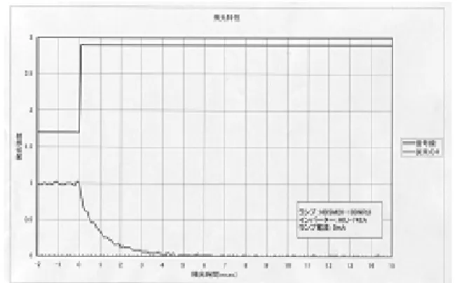
Fig 2. Residual time of conventional phosphors in CCFL [9]. In Fig. 2 (a), (b), (c), each phosphor shows significant different residual light characteristics andduration time of Red and Green phosphors need to be improved. New Red and Green phosphors are evaluated to improve residual light and the results are shown in Fig. 3. In Table 1, duration times of residual light are summarized before & after improvement of corresponding phosphor.
단잔광 냉음극관을 이용한 잔상없는 TFT-LCD에 관한 연구
147
(a) Residual time of improved red phosphor.(b) Result of residual time of improved green phosphor.
Fig 3. Residual time of improved red and green phosphors in CCFL [9].
Table 1. Duration time of residual light before and after improvement with respect to phosphor [9].
Red Green Blue
Before 4.7 ms 11 ms 1 ms
After 2 ms 1 ms -
Lamp with reduced residual light has brightness of 20%
smaller than that of conventional lamp and there is more reduction of brightness by blinking operation. So, to verify the effect of blinking B/L in LCM, a prism sheet is added to get higher brightness.
Blinking signal is applied to inverter with synchro- nized with Vsync signal and it divided 1 frame to 60%
turn on time and 40% turn off time. To get the same brightness to conventional lamp, lamp was over-driven from general 6mA to 10mA.
In case of 17 inch SXGA (1280×1024 resolution), there is 1280 de(data enable) signal within 1 frame and blinking signal is generated by counting de signal. To get proper timing, delayed de signals d_de and dd_d were made from flip-flop as shown in Fig. 5.
6 4
Vsync
Blinking interval
Fig 4. Generating blinking signal using Vsync signal
de vsync
d_de dd_d
de_counter => 1 2 1280 reset 1
de_counter =>
vsync
1234 … 768769 770 1280
blink signal
6 4
de_counter =>
vsync
1234 … 768769 770 1280
blink signal
6 4
Fig 5. Generating blinking signal using de signal counting
6:4 ratio of white-period to black-period was obtained by appointing 768(60%) dd_d’s of 1280 as white-period and 512(40%) dd_d’s as black-period. This method is very simple algorithm to get stable blinking signal at Vsync.
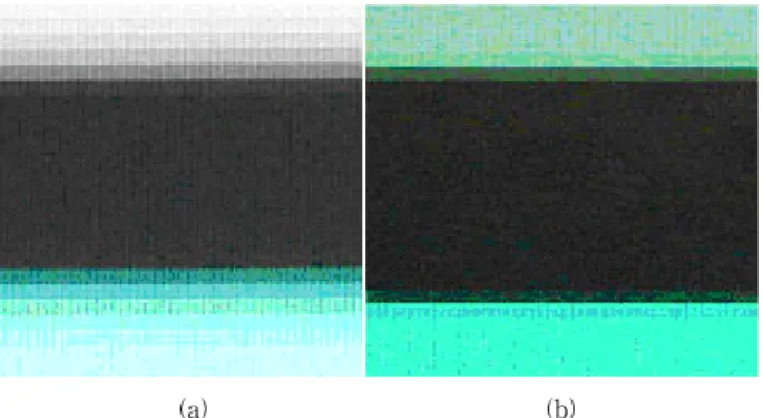
Display quality with blinking backlight was evaluated by measuring response waveform and by nakedeye. Fig. 6 represents response characteristics with and without blinking drive. Black screen is successfully inserted made by blinking drive as shown in Fig. 6 (b), and effect on image sticking in moving picture was excelled. Figure 7 is photograph of vertically moving image with 1/22.8sec shutter speed.
Figure 7 (a) is photographic result without blinking and Figure7 (b) that with blinking and over-driving. In these photographs, improvement of residual image is easily verified.
(a) Optical data in conventional LCD driving.
통신위성우주산업연구회논문지 제7권 제3호
148
(a) Optical data in blinking and overdriving LCD driving.Fig 6. Improvement of optical response charac-teristics in blinking & overdriving method.
(a) (b)
Fig 7. Photographic result of conventional driving and blinking&overdriving method.
Ⅳ. Conclusion
We studied improvement of image-sticking using BLU of flasher by creating CRT-like moving picture image.
Algorithm to make blinking signal with 6:4ratio was proposed by using de counter with synchronized with Vsync signal. The improvement of dynamic picture image embodiment was verified by experimental results, and these results are expecting to be applied to the development of TV and Multimedia LCD hereafter.
Reference
[1] H. Zou, K. W. Besson, J. Wilson, S. Zimmerman, and M.
McFarland, "Required and achievable backlight luminance for CRT-replacement LCD monitors", SID Digest 1997, pp.
373-376 (1997).
[2] T. Fukuzawa, T. Toyooka, Y. Sakaguchi, K. Takeda, and F.
Yamada, "Rapid-response fluorescent lamps for field sequential full-color LCDs", SID Digest, pp. 247-250 (1998).
[3] J. F. Saver, M. V. Hoffman, and F. A. Hummel, "Phase equilibria and Tin-activated luminescence in strontium orthophosphate systems", Journal of the electrochemical society, pp. 1103-1110 (1961).
[4] T. Uchida, K. Saitoh, T. Miyashita, and M. Suzuki, "Field sequential full color LCD without color filter for AM-LCD",
IDRC Digest of Technical papers, pp. 37-40 (1997).
[5] A. C. Newport and A. Vecht, "Optimized photo-luminescent phosphors for UV-excited light-emitting systems", SID Digest 1998, pp.239-242 (1998).
[6] W. Sautter, T. Kallfass, G. Bader, and E. Lueder "A backlight system providing variable viewing angles for transmissive LCDs", SID Digest 1998, pp. 235-238 (1998).
[7] K. Hathaway, J. Hawthorne, and A. Fischer, "Advancements in backlighting technilogies for LCDs", SPIE Vol. 1664, High-Resolution Display and Projection Systems, pp.
106-108 (1992).
[8] Y. Mesaki, A. Sotokawa, A. Tanaka, M. Tomatsu, K. Kaiwa, H. Yuzu, and M. Kato, "New backlight technologies for LCDs", SID Digest 1994, pp. 281-284 (1994).
[9] Matsushita West Electric Co., Ltd.
저자
최 대 섭(Dae-Seub, Choi)
․1995 2월:북해도 대학교 대학원 박사
․1985년 ∼ 현재 : 서일대학교 전기과 교수
<관심분야> : 정보디스플레이, 태양광발전, 이동무선통신
신 호 철(Ho-Chul, Sin)
![Table 1. Duration time of residual light before and after improvement with respect to phosphor [9].](https://thumb-ap.123doks.com/thumbv2/123dokinfo/5039656.554296/3.892.106.404.117.307/table-duration-time-residual-light-improvement-respect-phosphor.webp)