• 검색 결과가 없습니다.

New Cooling System Design of BLDC Motor for Electric Vehicle Using Computation Fluid Dynamics Modeling

N/A
N/A
Protected

Academic year: 2021

Share "New Cooling System Design of BLDC Motor for Electric Vehicle Using Computation Fluid Dynamics Modeling"

Copied!
6
0
0

로드 중.... (전체 텍스트 보기)

전체 글

(1)

DOI http://dx.doi.org/10.9725/kstle.2013.29.5.318

New Cooling System Design of BLDC Motor for Electric Vehicle Using Computation Fluid Dynamics Modeling

Duc Thuan Vu and Pyung Hwang *

Department of Mechanical Engineering, Yeungnam University

*School of Mechanical Engineering, Yeungnam University

(Received May 2, 2013 ; Revised July 18, 2013 ; Accepted July 23, 2013)

Abstract − Overheating in electrical motors results in detrimental effects such as degradation of the insulation materials, demagnetization of magnets, increases in Joule losses, and decreases in motor efficiency and lifetime.

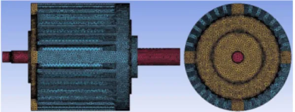
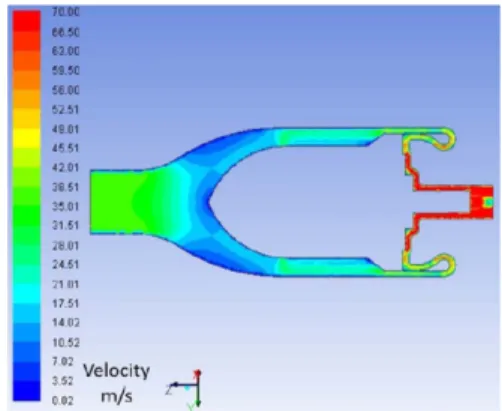
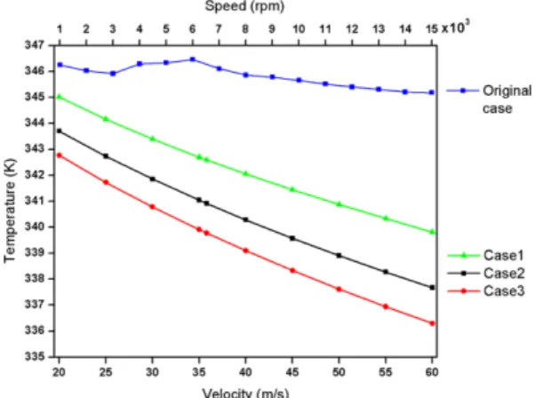
Thus, it is important to find ways to dissipate heat from the motor and to keep the motor operating at its most efficient temperature. In this study, a new design to guide air flow through a given brushless direct current (BLDC) motor is developed and the design is analyzed, specifically by using computational fluid dynamics (CFD) simulations. The results showed that the temperature distribution in the three proposed models is lower than that in the original model, although the speed of the cooling fan in the original model reaches a very high value of 15 × 10

3

rpm. The results also showed that CFD can be effectively used to simulate the heat transfer of BLDC motors.

Keywords − brushless direct current motor, hybrid electric vehicles, numerical method, cooling systems, computational fluid dynamics

1. Introduction

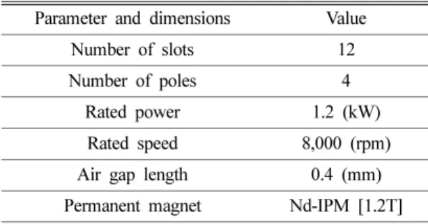
Brushless direct current (BLDC) motors are increas- ingly being employed in electrical vehicles (EVs) and hybrid electric vehicles because of their high effi- ciency, high power density, and minimal maintenance [1]. The ability of a BLDC motor to function as a gen- erator during regenerative braking makes it ideal for application to EVs.

The motor temperature is closely linked to the life and performance of BLDC motors. The stator winding temperature directly affects the durability of the wind- ing insulation system, whereas the rotor temperature affects the efficiency of the permanent magnet [2].

Overheating in the windings increases Joule losses because the electrical resistance of the winding mate- rial is highly temperature dependent [2]. Therefore, it is

imperative to conduct thermal analyses in the design of BLDC motors. Heat generated within an electric motor comes from two primary sources: electromagnetic losses and mechanical losses. Electromagnetic losses consist of Joule losses attributable to the flow of elec- tric current and core losses attributable to the hysteresis effect. Mechanical losses compose of bearing frictional losses and windage losses [3].

Most recent publications have focused on cooling system designs that use water, in which a water jacket is usually located between the stator frame and the sta- tor core [4-7]. According to the flow path of cooling water, a water jacket can be classified into two catego- ries: circumferential water jacket and axial water jacket. For the circumferential water jacket, the cooling water flows along the spiral-type path from one end of the stator frame to the other and removes the heat from the machine. For the axial water jacket, the plates are mounted on the surface of the stator to form many axial paths, which are connected together. The cooling water

Corresponding author : [email protected]

◎ 이 논문은 한국윤활학회 2013년도 춘계학술대회(2013.

4. 26. 서울테크노파크) 발표논문임.

(2)

channels.

To prevent the temperature of the winding from ris- ing, the unidirectional ventilated motor has been stud- ied [8-10]. The cooling airflows enter the motor from one end and exit from the other end in an axial direc- tion. Consequently, the windings and iron core are cooled directly with external air and the overall tem- perature of the motor decreases significantly. Never- theless, this method also has some drawbacks; for instance, the windings and other inside parts are not protected from moisture and dust, which may affect durability and the overall performance of the motor [11].

In this study, adaptive methods to guide air flow through a given BLDC motor are developed and the methods are analyzed, specifically by solving both the heat transfer and fluid dynamics problems, particu- larly the important factors such as the optimal shape and dimensions of air guide casings to ensure the best aerodynamic characteristics of flow in the channel. As a result, the thermal efficiency is increased as much as possible.

2. BLDC Motor and Proposed Cooling System

2-1. BLDC Motor

The 1.2 kW BLDC motor in a car air-conditioning

system with a cooling fan is shown in Fig. 1, and the corresponding specifications are tabulated in Table 1.

Fig. 1 shows front and side views of the analyzed motor. Air enters through the opening slots on the fan cover, passes through the fan, and enters the housing.

The rotor, stator, windings, and insulation are totally enclosed to protect them from moisture and dust, which affect the durability and overall performance of the motor.

2-2. Structure of proposed cooling system 2-2-1. Case 1: Cooling of motor fins

To clarify the influence of internal aerodynamics on the cooling system, a simple case of an air guide cas- ing is introduced, as shown in Fig. 2. In this case, the cooling air flows along the axial direction from one end of the cooling fins to the other and removes the heat from the motor.

2-2-2. Case 2: Cooling of motor housing surfaces For case 1, some parts of the motor (for instance, the back cover of the motor) seem to be unaffected by the air flow through the motor. As a result, a new design method is presented to improve the cooling efficiency of the motor. This is shown in Fig. 3. In this case, the Table 1. Specifications of analyzed motor

Parameter and dimensions Value

Number of slots 12

Number of poles 4

Rated power 1.2 (kW)

Rated speed 8,000 (rpm)

Air gap length 0.4 (mm)

Permanent magnet Nd-IPM [1.2T]

Fig. 1. Prototype of BLDC motor.

Fig. 2. Structure of cooling system for motor fins.

(3)

cooling air is guided to the rear of the motor housing and the back cover is directly cooled with external air.

Consequently, the overall temperature of the motor decreases significantly.

2-2-3. Case 3: Cooling of outer surfaces of the motor To obtain the highest cooling efficiency for a given motor, the proper method to guide cooling air flow through the entire outer surface of the motor is imple- mented by separating inflow into two parts so that the front cover is also cooled as much as possible. Fig. 4 describes the structure of the cooling system for the complete outer surface of the motor.

3. CFD Model Formulation

3-1. Grid model

To solve discrete equations in the finite volume method, first, the grid model is generated by ANSYS

ICEM CFD [12]. A tetrahedral mesh is created relatively easily by using smart functions, curvatures, proximity etc., with high mesh quality (more than 0.3). Further- more, controlling the density of the mesh according to problem requirements is also considered here, for example, for the regions in which the flow direction is changed significantly. Hence, the entire mesh is divided into approximately 1.5 million cells, as shown in Fig. 5.

3-2. Boundary conditions

The boundary conditions used for solving the heat transfer problem on the BLDC motor are as follows.

For the inlet, the boundary condition in terms of veloc- ity is used here, corresponding to each case of the inlet velocity. For the outlet, the pressure boundary condi- tion with atmospheric pressure is set. Additionally, the remaining boundaries are set to a solid wall. Thus, the casing walls, except the boundary walls of the second- ary flow in cases of new design methods, are assumed to be insulation walls and other walls are set up with specific values of temperature, which were obtained from calculations using ePhysics software [13].

3-3. Solution method

The air flow through a motor is simulated by solv- ing governing equations describing the properties of flow. For this, the continuity equation and the Navier- Stokes equations [14], commonly used in the compu- tational fluid dynamics (CFD) method, are the basic equations, as shown below:

(1)

(2)

∂ρ --- ∂ ∂t

∂x

j

--- ρu (

j

)

+ = 0

∂ρu

i

--- ∂ ∂t

∂x

j

--- ρu (

i

u

j

)

+ ∂p

∂x

i

--- ∂

∂x

j

--- µ

eff

∂u

i

--- ∂u ∂x

j

∂x

i

---

⎝ + ⎠

⎛ ⎞

+ –

= Fig. 3. Structure of cooling system for motor housing

surfaces.

Fig. 4. Structure of cooling system for complete outer surface of motor.

Fig. 5. Grid model.

(4)

heat walls (see section 2.2 for more details). The convec- tive heat transfer equation [14] is as follows:

(3) Here, h

f

denotes the fluid-side local heat transfer coefficient, T

w

and T

f

are the wall surface temperature and local fluid temperature, respectively, and q

rad

is the radiative heat flux.

4. Results and Discussion

4-1. Original BLDC model

Some surface regions of the motor, such as half of a fin side or the back cover, seem to not be cooled, as shown in Fig. 6. This is also one of the drawbacks when a fan is used to cool the motor. Although the speed of the cooling fan reaches a very high value, the temperature on the housing surface is still high: 345.2 K at 15 × 10

3

rpm.

4-2. Proposed cooling models 4-2-1. Case 1

In case 1, motor fins are cooled by cooling air through it with a lower temperature (300 K). The results are presented in Figs. 7 to 9. By using this method, the average temperature on the fins is signif-

icantly reduced, from 353.506 to 342.587 K, in pro- portion to an inlet velocity of 35.805 m/s. Additionally, all of the fin surfaces are cooled and a vortex region with hydraulic loss can be created, which is apparently not detected in most domains, except for one near to the outlet of the model. This is one reason that case 2 is q h =

f

( T

W

– T

f

) q +

rad

Fig. 6. Contour of temperature distribution on motor housing surfaces.

Fig. 7. Contour of velocity distribution.

Fig. 8. Contour of temperature distribution on motor fins.

Fig. 9. Contour of temperature distribution on Z

plane.

(5)

introduced in the next section.

4-2-2. Case 2

A special design for cooling all the surfaces of the motor housing is developed to improve the cooling efficiency of forced convection and to minimize the hydraulic loss in the system. Hence, the back cover and back shaft included are clearly cooled, as shown by the blue and green regions in Fig. 11. Because air velocity through this region is so high, either the heat transfer rate or carrying heat increases significantly.

4-2-3. Case 3

Case 3 is similar to case 2; however, the air guide casing is redesigned including the front cover of the motor so that the previous design is not changed and the new design favorably affects the final results.

Some of these results are shown in Figs. 12 to 14.

The variation of the specific quantities related to heat transfer with respect to velocity is shown in Fig. 15.

In Fig. 15, the mean temperature obtained in the motor decreases from case 1 to case 3, corresponding to the different design methods of the air guide casing.

These three cases are significantly lower than the orig- inal case of the BLDC model. The temperature in Fig. 10. Contour of velocity distribution.

Fig. 11. Contour of temperature distribution on motor housing surfaces.

Fig. 12. Contour of velocity distribution.

Fig. 13. Contour of temperature distribution on housing surfaces.

Fig. 14. Contour of temperature distribution on front

cover.

(6)

cases 2 and 3 is decreased much more than in case 1, up to 2.14 K. Furthermore, for case 3, the front cover of the motor is also cooled apparently well (see Fig.

14). This means that the entire outer surfaces of the motor were efficiently cooled.

5. Conclusions

The cooling system of a BLDC motor was investigated by adaptive design methods addressing the effects of internal aerodynamics. Thus, the cooling efficiency obtained from the proposed methods is significantly higher than the original efficiency. Thus, these results can be used as reference materials in motor design and manu- facture. In addition, to further increase the cooling effi- ciency for this system, new approaches such as the design of a proper cooling fan based on the proposed methods will continue to be studied in the future.

Acknowledgment

This research was funded by Yeungnam University.

References

1. Jang, S. M., Cho, H., and Choi, S. K., “Design and Analysis of High-Speed Brushless DC Motor for Centrifugal Compressor,” IEEE Transaction on Magnet-

CFD,” Sustainable Research and Innovation Confer- ence, May, 2011.

4. Fan, J. X., Zhang, C. N., Wang, Z. F. ,and Strangas, E. G., “Thermal Analysis of Water Cooled Surface Mount Permanent Magnet Electric Motor for Elec- tric Vehicle,” Electrical Machines and Systems (ICEMS), IEEE International Conference, 2010.

5. Tong, W., Tang, R., An, Z. L., and Shen, Q., “Water Cooling System Design and Thermal Analysis for Low Speed Permanent Magnet Machines,” Electri- cal Machines and Systems (ICEMS), IEEE Interna- tional Conference, 2011.

6. Song, L., Li, Z., Gao, J., Zeng, Q. C., and Wang, F.,

“3D Thermal Analysis of Water Cooling Induction Motor used for HEV,” Electrical Machines and Sys- tems (ICEMS), IEEE International Conference, 2008.

7. Ye, Z. N., Luo, W. D., Zhang, W. M., and Feng, Z.

X., “Simulative Analysis of Traction Motor Cooling System Based on CFD,” Electric Information and Control Engineering (ICECE), IEEE International Conference, 2011.

8. Takafumi, N., Kasumi, S., Shozo, H., Fuminori, I., and Masami, H., “Cooling Airflow in Unidirectional Venti- lated Open-Type Motor for Electric Vehicles,” IEEE Transactions on Energy Conversion, Vol. 21, No. 3, September 2006.

9. Tong, W., Wu, S., An, Z. L., Zhang, H., and Tang, R., “Cooling System Design and Thermal Analysis of Multibrid Permanent Magnet Wind Generator,”

International Conference on Electrical and Control Engineering, 2011.

10. Zhang, Y., Ruan, J., Huang, T., Yang, X., Zhu, H., and Yang, G., “Calculation of Temperature Rise in Air Cooled Induction Motors Through 3-D Coupled Electromagnetic Fluid-Dynamical and Thermal Finite- Element Analysis,” IEEE Transactions on Magnetics, Vol. 48, No. 2, February 2012.

11. Branch, F. E., “Keeping Motor Windings Dry,” Facili- ties Engineering Branch, Denver Office, Denver, Colorado, 1991.

12. ANSYS, ICEM CFD User’s Manual, Version 13, 2010.

13. Vu, D. T. and Hwang, P., “Thermal Analysis of BLDC Motor for air conditioning system,” KSTLE confer- ence, Seoul, South of Korea, April, 2012.

14. ANSYS, FLUENT User’s Manual, Version 13, 2010.

Fig. 15. Variation of temperature versus velocity and

cooling fan speed.

수치

Fig. 1. Prototype of BLDC motor.
Fig. 4. Structure of cooling system for complete outer surface of motor.
Fig. 6. Contour of temperature distribution on motor housing surfaces.
Fig. 12. Contour of velocity distribution.
+2

참조

관련 문서