스테레오 카메라의 최적 위치 및 방향
An Optimal Position and Orientation of Stereo Camera
최형식*, 김환성*0, 신희영*, 정성훈*0
Hyeung-Sik Choi*, Hwan-Sung Kim*0, Hee-Young Shin*, and Sung-Hun Jung*0 요 약
모션 및 무인 차량의 깊이 제어를 위해 스테레오 비전 분석을 하였다. 스테레오 비전에서 3차원 좌표의 깊 이 정보는 스테레오 이미지 사이의 포인트를 식별한 후 삼각 측량을 통해 얻을 수 있다. 그러나 항상 몇몇 이 유 때문에 삼각 측량의 오류가 발생한다. 비전 삼각 측량의 이러한 오류는 카메라의 위치와 방향에 주의하여 배열함으로써 완화 될 수 있다. 본 논문에서는 무인 차량을 위해 카메라의 최적의 위치와 방향을 결정하는 방 법을 제시하였다.
Abstract
A stereo vision analysis was performed for motion and depth control of unmanned vehicles. In stereo vision, the depth information in three-dimensional coordinates can be obtained by triangulation after identifying points between the stereo image. However, there are always triangulation errors due to several reasons. Such errors in the vision triangulation can be alleviated by careful arrangement of the camera position and orientation. In this paper, an approach to the determination of the optimal position and orientation of camera is presented for unmanned vehicles.
Key words : sensor system(센서 시스템), active stereo vision system(능동 스테레오 비전), stereo vision (스테레오 비전), unmanned vehicle(무인 차량)
* 한국해양대학교(Korea Maritime University) ‧ 제1저자(First Author) : 최형식(Hyeung-Sik Choi)
0 교신저자 (Corresponding Author) : 김환성(Hwan-Sung Kim Tel : +82-51-410-4334 email : [email protected]), 0 교신저자 (Corresponding Author) : 정성훈(Sung-Hun Jung Tel : +82-51-410-5354 email : [email protected])
‧ 접수일자 : 2013년 5월 15일 ‧ 심사(수정)일자 : 2013년 5월 15일 (수정일자 : 2013년 6월 25일) ‧ 게재일자 : 2013년 6월 30일 http://dx.doi.org/10.12673/jkoni.2013.17.3.354
I. Introduction
A vision system is an important sensor for the unmanned vehicle such as the unmanned forklift for approaching destination. In order for the unmanned forklift to move with loads without an human beings, they need a number of sensors such as the gyro sensor, supersonic wave sensor, infrared rays sensor, and vision sensor. Out of the sensors, one of the most important
sensor is the vision sensor. A number of researches were performed in application of vision sensor to the unmanned forklift [1],[2]. However, the vision sensors in the research are single vision system such that it should be used with other sensors to find depth information.
However, there are always triangulation errors due to several reasons and those have been studied [3]-[6].
We focus on a stereo vision system with position and orientation errors due to several reasons. In section 2, Sensitivity for the stereo vision sensor system is
explained. Also, System error equation is explained in section 3.
Ⅱ. Sensitivity for the stereo vision sensor system
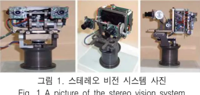
The stereo vision sensor system is composed of two cameras capable of yawing and pitching motion as shown in Fig. 1. Each camera has two degree-of- freedom (DOF).
The stereo camera is used to find the depth information between the unmanned vehicle and an object.
In this section, the system sensitivity equation to measure triangulation error of the stereo vision system is derived.
그림 1. 스테레오 비전 시스템 사진 Fig. 1 A picture of the stereo vision system
In the following two equations, x and y can be set as functions of X, Y, and Z by fixing the camera orientation variables, θ, a constant. Denoting them in function formation, we get
x=(Xrcθ+Yrsθ)/k = f(X,Y,Z) (1) y=(-XrsθcaYrcθcaZrSa)/k = f(X,Y,Z) (2)
Substituting x1, y1, Xr1, Yr1, and Zr1 into x, y, Xr, Yr, and Zr, respectively, in order to indicate the position and orientation of camera one, yields
x1=(Xr1cθ1+Yr1sθ1)/k1 = f11(X,Y,Z) (3) y1=(-Xr1Sθ1Cα1+Yr1Cθ1Cα1+Zr1Sα1)/k1
= f12(X,Y,Z) (4)
Substituting x2, y2, Xr2, Yr2, and Zr2 into x, y, Xr, Yr, and Zr, respectively, in order to indicate the position and orientation of camera two, yields
x2=(Xr2cθ2Yr2sθ2)/k2=f21(X,Y,Z) (5) y2=(-Xr2sθ2ca2Yr2cθ2cα2+Zr2sα2)/k2=f22(X,Y,Z) (6)
There are three ways to derive the system error equation to measure the triangulation error. These ways are dependent on which camera coordinates on the image plane are used. If only xx, yx, and x2 are used to determine the coordinates of the task, X, Y, and Z, equations (3), (4), and (5) are used. Taking partial differentiations of those equations, and expressing in matrix notation yield
(7) Assuming that very small errors occur in locating a scene on both of the stereo image, equation (7) can be expressed as
(8) where
(9)
in which
∂f11/∂X = cθ1/k1+(Xr1cθ1+Yr1sθ1) (sθ1sα1/λ)/k12 (10)
∂f11/∂Y =Sθ1/k1-(Xr1Cθ1+Yr1Sθ1)(Cθ1Sα1/λ)/k12 (11)
∂f11/∂Z =(Xr1cθYr1sθ1 (cα1/λ)/kl2 (12)
∂f12/∂X = -Sθ1Cα1/k1+
(-Xr1sθ1cα1+Yr1cθ1cα1+Zr1sα1)(sθ1sα1/λ)/k12
(13)
∂f12/∂Y = cθ1Cα1/k1-
(-Xr1sθ1cα1+Yr1cθ1ca1+Zr1sα1)(cθ1Sα1/λ)/kl2 (14)
∂f12/∂Z = sα1/k1+
(-Xr1sθ1cα1+Yr1cθ1cα1+Zr1sα1)(Cα1/λ)/k12 (15)
∂f21/∂X = cθ2/k2+(Xr2cθ2+Yr2sθ2)(sθ2sα2/λ)/k22 (16)
∂f21/∂Y = sθ2/k2-(Xr2cθ2+Yr2sθ2)(cθ2Sα2/λ)/k22
(17)
∂f21/∂z=(Xr2cθ2+Yr2sθ2)(cα2/λ)/k22 (18)
The measurement errors in three-dimensional coordinates due to the input errors, Δx1, Δy1, Δx2 in locating the projection of robot task on the image plane, are then easily determined by the following equation as
(19) Similarly, the measurement errors in three-dimensional coordinate due to the input errors, Δx1, Δy1, Δy2 in locating the projection of robot task, are determined by following equation.
(20) where
(21)
in which
∂f22/∂X=-sθ2cα2/k2+(-Xr2sθ2cα2+
Yr2cθ2cα2+Zr2sα2)(sθ2Sα2/λ)/k22
(22)
∂f22/∂Y=cθ2ca2/k2-(-Xr2sθ2cα2+
Yr2cθ2ca2+Zr2sα2)(cθ2Sα2/λ)/k22 (23)
∂f22/∂Z=sα2/k2+(-Xr2sθ2cα2+Yr2cθ2cα2+ Zr2sα2)(cα2/λ)/k22
) (24)
Also all the Ax1, Ay1, Ax2, and Ay2 can be used to determine the measurement errors in three-dimensional coordinate as
(25) where
(26)The J3 in Eq. (26) is a four by three matrix. If the matrix (J3T
J3)-1J3T
is applied on both sides of equation (25), we obtain
(27) Three ways of derivation of the system sensitivity equation to measure the triangulation error have been
made so far. Equations (19), (20), and (27) are the matrices to measure the error in three-dimensional coordinate by the input error on the image planes.
Similarly, the system error equation to measure the triangulation error is derived in next section
Ⅲ. System error equation
The depth information of the dimensional coordinates can be obtained based on the projected scene on the stereo image. Because of image resolution and possible computation errors in image correlation and human error in locating ascene on the camera image, a certain degree of inaccuracy in determining the correct depth information of the robot task in three- dimensional coordinate always occurs. In other words, if we assume that those input errors, x1', y1', x2', and y2' on the image planes occur, the corresponding errors X1', Y1' , and Z1' are caused in the three-dimensional coordinate. In this approach, the system error equation to measure the triangulation error is derived in this section.
The system error equation is based on equations (6) and (7). If only x1, y1, and x2 are used, the system error equation can be expressed as the following matrix by setting xx1 = x1+x1' , yy1 = y1+y1', xx2 = x2+x2', and yy2
= y2+y2',
′
′′
′
′
(28) where A' =
(29)
If only xl, y1, and y2 are used, the system error equation can be expressed as,
′
′′
′
′
(30) where B' =
(31)
If all the variables, xx1, yy1, xx2 and yy2 are used, the system error equation can be expressed as,
′
′′
′
′ ′
(32) where C' =
(33)
P' = (xx2sθ2Sα2+λcθ2)(Xo2-Xo1)+(-xx2Cθ2Sα2+ λsθ2)(Yo2-Yo1)+xx2cα2(Zo2-Zo1) (34)
q' = (yy2sθ2sα2-λsθ2Cα2)(Xo2-Xol)+(yy2cθ2sα2+ Xcθ2cα2)(Yo2-Yo1)+(yy2cα2+λsα2)(Z02-Z0l) (35)
The procedure of deriving the system error equation is quite similar to that of system sensitivity equation, so that only equation (32) which uses all the input variables is derived.
In equation (33), the system error can be expanded into two equations as, C' = C + Cl where C is decided (32) and (37), and C1 matrix is expressed as,
′′′ ′′′ ′′′′ ′ ′
(37)The matrix on the left side of the equation (32) can be expanded into the following matrices,
′
′′
′
′
′′
′
(38)
From equation (38), the following equation yields
′
′′
′
′′ ′ ′
(39)where
P'-P = X2'Sθ2Sα2(Xo2 -Xo1) -x2'cθ2Sα2(Yo2-Yo1) + x2'cα2(Zo2—Zo1) (40)
q'-q = y2'sθ2sα2(Xo2-Xo1) -y2'cθ2α2 (Yo2-Yo1) + y2'cα2(Zo2-Zo1) (41)
All the terms of equation (39) have four rows.
Dividing the first, second, third, and fourth row of both sides of equation (39) by x1', y1', x2', and y2' respectively yields
′′′′′′′′
′′′
′ ′
′ ′
where we set the matrix C' as
′
′′′′
(43) We set k' ask' = λk (44)
Substituting θ1, αl Xo1, Yo1, and Zo1 into θ, α, X0, Y0, and Z0, respectively, to indicate camera one coordinate, yields
k1' = λk1 = -sθ1Sα1Xrl+cθ1sα1Yr1-cαZrl+λ (45)
Substituting θ2, a2, Xo2, Yo2, and Zo2 into θ, α, Xc, Yc, and Z0, respectively, to indicate the camera two coordinate, yields
k2' = λk2 = -sθ2sα2Xr2+cθ2Sα2Yr2-cα2Zr2+λ (46)
Rearranging equation (42) yields
′′′′′′′′
′′′
′ ′ ′′ ′′ ′ ′
(47)If we set
′′′′′′′′
(48) the D matrix is a four by three matrix. In order to get the errors, X1' , Y1', and Z1' of depth informations in the three-dimensional coordinate affected by the input errors, X1', Y1' and Z1' on the image plane in the camera coordinates, the least squares method should be applied.The least squares method is applied by pre- multiplying on each side of the above equation by (DTD)-1DT, which
yields
′′
′
′ ′ ′ ′ ′′ ′ ′
(49)The purpose of the optimal arrangement of position and orientation of stereo camera is to decide the best stereo camera arrangements to produce the least triangulation error as mentioned before. The depth error X1', Y1', and Z1' in three-dimensional coordinates is affected by the variation of the ten explicit variables, Xrl, Yrl, Zrl, Xr2, Yr2, Zr2, x1, y1, x2, y2, and four implicit variables, α1, θ1, α2, and θ2. Here the aiming angles of the stereo camera to the task and the mapped position of robot task on the camera image plane are dependent on each other. In other words, x1, y1, x2, y2 can be treated as implicit variables and at the same time α1,θ1,α2 and θ2
can be set as explicit variables.
In order to solve the optimization problem, the limits of the image plan should be set within the image plane size, because the image of task can not be mapped out of the image plane. The smallest absolute value of the error, X1' , Y1', and Z1' in three-dimensional coordinate in equation (49) should be obtained. If the absolute value of the error is set ERR, the expression is
ERR = sqrt(X1'2+Y1'2+Z1'2) (50)
In order to find the minimum value of the equation (50), a program based on the "complex" method of M. J.
Box is used [6]. The program finds the minimum of a multi variable, nonlinear function subject to nonlinear inequality constraints.
Ⅳ. Conclusion
A stereo vision analysis was performed for motion and depth control of unmanned vehicles. In this paper,
a system error equation for the stereo vision is derived.
Also, an approach to the determination of the optimal position and orientation of camera which produce the least triangulation error equation is presented.
Acknowledgment
This research was supported by a grant (11Transportation System-Logistics02) from Transportation System Efficiency Program funded by Ministry of Land Transport and Mariti me Affairs of Korean government.
References
[1] Vucobratovic M. and Stepanenko M., “Mathematical Models of General Anthropomorphic Systems”, Mathematical biosciences, Vol. 17, No. 3-4, pp.
191-242, 1973.
[2] Gubina, F., Hemami, H., and McGhee, R. B., “On the Dynamic Stability of Biped Locomotion”, Biomd.
Engineering, IEEE transactions on Vol. 21, No. 2, pp.
102-108, 1974.
[3] Duda, R. 0. and P. E. Hart, Pattern Recognition and Scene Analysis, Wiley, New York, 1973.
[4] Slama, C. C., H. Ebner, and L. Fritz., “Analytical Triangulation”, in Manual of Photogrammetry, 4th ed., ed. C. C. Slama, American Society of photogrammetry, Falls Church, Va., pp. 476-518, 1980.
[5] Faugeras, O.D., N. Ayache, and B. Faverjon, Building visual maps by combining noisy Stereo Measurements, in IEEE International Conference on Robotics and Automation, San Francisco: CA, pp.
1433-1438, Apr. 1986.
[6] M. J. Box, “A New Method of Constrained Optimization and A Comparison with Other Methods”, in The Computer Journal, Vol. 8, pp. 42-52, 1965.
최 형 식 (Hyeung-Sik Choi)
1993년 2월 : North Carolina State Univ.
(공학박사)
1993년~현재 : 한국해양대학교 기계․에너지시스템공학부 교수
관심분야 : Humanoid Robot, Unmanned Underwater, Vehicle, Two Cooperating robot arms
김 환 성 (Hwan-Sung Kim)
1996년 2월 : 일본 Kumamoto Univ.
(공학박사)
1998년~현재 : 한국해양대학교 물류시스템공학과 교수
관심분야 : 물류기기 및 자동제어
신 희 영 (Hee-Young Shin)
2006년 3월 : 한국해양대학교 기계․에너지시스템공학(공학사) 2012년 3월~현재 : 한국해양대학교 기계․에너지시스템공학 석사과정
관심분야 : Unmanned Underwater Vehicle, 자동제어
정 성 훈 (Sung-Hun Jung)
2007년 2월 : 한국해양대학교(공학박사) 2010년 8월~현재 : 한국해양대학교 산업기술연구소 산학연구교수
관심분야 : Maritime Communications, IT Convergence, AGV, Mobile Contents