http://dx.doi.org/10.12673/jkoni.2014.18.1.84
This is an Open Access article distributed under the terms of the Creative Commons Attribution Non-CommercialLicense(http://creativecommons .org/licenses/by-nc/3.0/) which permits unrestricted non-commercial use, distribution, and reproduction in any medium, provided the original work is properly cited.
Received 21 October 2013; Revised 10 February 2014 Accepted 13 February 2014
*Corresponding Author; Jang-Woo Park
Tel: +82-61-750-3592 E-mail: [email protected]
모바일 WiMAX의 연결성 매개변수 효율 분석
Analysis of Parameters Effecting MOBILE WiMAX Connectivity
올리 로이 초우드후리
1· 아리프 카이세르
2· 에크라물 카빌
2· 서브라타 쿠말 아디탸
2· 박장우
1*1순천대학교 정보통신공학과
2방글라데시 다카대학교 전자 및 정보공학, 응용 물리학과
Olly Roy Chowdhury1· Arif Kaiser2 · Ekramul Kabir2 · Subrata Kumar Aditya2 · Jang-Woo Park1*
1Department of Information and Communication Engineering, Sunchon National University, Suncheon, South Korea.
2*Department of Applied Physics, Electronics and Communication Engineering, University of Dhaka, Dhaka, Dangladesh.
[요 약]
Microwave Access(WiMAX)는 20세기 통신 시스템에서 세계적인 정보처리 상호 운용에 매우 효율적인 기술이라 할 수 있다. 이 기술은 광대역 속도의 통신을 케이블 없이 무선으로 제공하며, IEEE 802.16 표준(무선 MAN 이라고도 함)을 기반으로 정의된다.
IEEE 802.16e에서 모바일 WiMAX는 GSM, CDMA기술 보다 더 효율적인 기술로 정의된다. 본 논문에서는 WiMAX에 사용되는 4 종류의 Modulation(BPSK, QPSK, 2개의 QAM)을 비교하여 통신 시 Cell 영역에 대한 효율성에 대해 연구 하였다. 또한, 시골과 도 시와 같은 지역을 위한 Cost 231 모델과 외곽 지역을 위한 모델인 Erceg-Greenstein의 2가지 모델을 적용하였고, 이를 기반으로 Cell 영역에서 주파수, 기지국 안테나의 높이, 전송 전력, SNR 등의 효율성에 대한 연구를 수행하였으며, uplink와 downlink에 대한 실 험 결과를 통해 본 논문에서 제기한 WiMAX의 Modulation에 따른 효율을 분석하였다.
[Abstract]
Worldwide Interoperability for Microwave Access (WiMAX) is an efficient technology for 20th century communication system.
The technology provides broadband speed without the need for cables and is based on the IEEE 802.16 standard(also called Wireless MAN). Mobile WiMAX is defined as IEEE802.16e which is advanced and efficient technology for mobile telecommunication rather than GSM, CDMA technology. In this work link budget calculation for WiMAX have been done. Cell range have been calculated over digital modulations and they are BPSK, QPSK and QAM. Here different types of models like Cost 231 model have been used for different types of areas like open, rural and urban areas and Erceg-Greenstein model for sub-urban areas. Effect of various parameters like frequency, base station antenna height, transmission power and SNR over cell range have been studied. Analysis have done for both uplink and downlink.
Key word : WiMAX, BPSK, QPSK, QAM.
색인어 : WiMAX, BPSK, QPSK, QAM, 통신효율분석.
Ⅰ. INTRODUCTION
Within the last two decades, communication advances have reshaped the way we live our daily lives. Wireless communication has grown from an obscure, unknown service to a ubiquitous technology that serves almost half of the people on Earth.
Broadband wireless access (BWA) technical solutions and products have been available for some time. Mobile WiMAX is a broadband wireless solution that enables convergence of mobile and fixed broadband networks through a common wide area broadband radio access technology and flexible network architecture. The Mobile WiMAX Air Interface adopts Orthogonal Frequency Division Multiple Access (OFDMA) for improved multi-path performance in non-line-of-sight environments.[1]
The IEEE 802.16 Working Group on Broadband Wireless Access Standards, which was established by IEEE Standards Board in 1999, aims to prepare formal specifications for the global deployment of Broadband Wireless Metropolitan Area Networks.
The Workgroup is a unit of the IEEE 802 LAN/MAN Standards Committee. An amendment to 802.16-2004, IEEE 802.16e-2005 (formally known as IEEE 802.16e), addressing mobility, was concluded in 2005. This implementation a number of enhancement to 802.16-2004, including better support for Quality of Service (QoS) and the use of Scalable OFDMA, and is sometimes called
“Mobile WiMAX”, after the WiMAX forum for interoperability.
The introduction of interoperable WiMAX technology solution has spurred a spirited discussion on how best combine fixed and mobile infrastructure solution to create one cohesive network [2].
Baig [3] gave guidelines for channel estimation, antenna beam forming and parameters affecting the beam forming. The problem of two unknown beam forming can be solved by MUSIC algorithm [4]. In 2006 Michael Carlberg Lex and Annelie Dammander approaches the WiMAX Network Architecture but the research indicates that upper layer protocol need to be modified to execute the handover process more efficiently [5].
This paper focuses on the variation of cell range with respect to frequency, antenna height, transmitted power and signal-to-noise ratio for both Uplink and Downlink. It also exhibits simulation diagrams that have been drawn by using tabulated data provided by the calculations performed using cell range equations for Cost-231 model and Erceg-Greenstein model, consequently analyze the diagrams and draws a conclusion.[1]
Ⅱ. Digital modulation and OFDM
Four modulations are supported by the IEEE 802.16 standard:
BPSK, QPSK, 16-QAM and 64-QAM.A short explanation of them are given in this section:[6]
(a) Binary phase shift keying (BPSK):
The BPSK is a binary digital modulation; i.e. one modulation symbol is one bit. A digital phase modulation, which is the case for BPSK modulation, uses phase variation to encode bits: each modulation symbol is equivalent to one phase. The phase of the BPSK modulated signal is π or -π according to the value of the data bit.
(b) Quadrature phase shift keying (QPSK):
When a higher spectral efficiency modulation is needed, i.e.
more b/s/Hz, greater modulation symbols can be used. For example, QPSK considers two-bit modulation symbols.
(c) Quadrature amplitude modulation (QAM): 64 QAM and 16 QAM
The QAM changes the amplitudes of two sinusoidal carriers depending on the digital sequence that must be transmitted; the two carriers being out of phase of +π/2, this amplitude modulation is called quadrature.
It should be mentioned that according to digital communication theory, QAM-4 and QPSK are the same modulation (considering complex data symbols). Both 16-QAM (4 bits/modulation symbol) and 64-QAM (6 bits/modulation symbol) modulations are included in the IEEE 802.16 standards. The 64-QAM is the most efficient modulation of 802.16. Indeed, 6 bits are transmitted with each modulation symbol.[6]
그림 1. A 64-QAM 관계도 [7]
Fig. 1. A 64-QAM constellation [7]
그림 2. 시간 및 SC와 OFDM의 주파수 표현 OFDM에서는 N 데이터 심볼은 직교 부반송파를 N에서 동시에 전송됨 [8]
Fig. 2. Time and frequency representation of the SC and OFDM. In OFDM, N data symbols are transmitted simultaneously on N orthogonal subcarriers [8]
OFDM Transmission:
OFDM is a very powerful transmission technique. It is based on the principle of transmitting simultaneously many narrow-band orthogonal frequencies, often also called OFDM subcarriers or subcarriers. The number of subcarriers is often noted N. These frequencies are orthogonal to each other which (in theory) eliminates the interference between channels. Each frequency channel is modulated with a possibly different digital modulation (usually the same in the first simple versions). The frequency bandwidth associated with each of these channels is then much smaller than if the total bandwidth was occupied by a single modulation. This is known as the Single Carrier (SC) (see Figure 2).
A data symbol time is N times longer, with OFDM providing a much better multipath resistance.[8]
Adaptive modulation:
Adaptive modulation is a term used to denote the matching of the modulation, coding and other signal and protocol parameters to the conditions on the radio link [9]. The system can adjust the modulation scheme depending upon the requirement. Owing to this type of modulation scheme the range can also be increased with the help of a high modulation scheme.
Ⅲ. Link budget and path loss model
A link budget is the accounting of all of the gains and losses from the transmitter, through the medium (free space, cable, waveguide, fiber, etc.) to the receiver in a telecommunication system. It accounts for the attenuation of the transmitted signal due to propagation, as well as the antenna gains, feed-line and miscellaneous losses. Randomly varying channel gains such as
fading are taken into account by adding some margin depending on the anticipated severity of its effects. The amount of margin required can be reduced by the use of mitigating techniques such as antenna diversity or frequency hopping[10].
A simple link budget equation looks like this:
(1)
Path Loss Models for NLOS
Erceg-Greenstein Model (Used For Sub-Urban Areas)
∆
∆
(2)
These parameters can be calculated as -
(3)
(4)
∆
(5)∆
and
(6)
∈ (7)
For mobile log normal shadowing is considered from 5 dB to 12 dB.
We Assume,
= Camier Frequency(MHz)
= Base Staion (BS) Height (m)
= Mobile Staion (MS) Height (m) = BS to MS distance (Km)
= 0.1Km (Chooses as reference distance)
= Carrier Wave Length (Km)
= c/f ; Where, c = Speed of Light
Path loss exponent is expressed by a, b, c which are the constants depended on terrain categories. Erceg-Greenstein Model exhibits three types of terrains – Terrain A (Hilly and Dense trees), Terrain B (Flat with Moderate dense tress) and Terrain C (Flat and Plain Land)( see tab.1).
표 1. 다른 영역의 상수 값 [11]
Table 1. Values of constant in different terrain [11]
Terrain
Constant A B C
a 4.6 4.0 3.6
b(m-1) 0.0075 0.0065 0.002
c(m) 12.6 17.1 20.0
Cost-231 Model (Used for Urban, Rural and Open Place) Cost-231 Model is the extended version of Hata Model. We have used Cost 231 propagation model for Mobile WiMAX coverage area calculations allowing for urban, rural and open areas. The proposed model for path loss is –
(8)
Where, a (hm) is the correction factor for effective mobile antenna height.
(9)
and for
(10)
and for
(11)
and
(12)
(13)
(14)
(15)
EIRP (Effective Isotropic Radiate Power) and SNR (Signal to Noise Ratio) Calculation:
EIRP (Downlink) (dBm) = BS Power (dB) + BS Antenna Gain (dBi) + Cyclic Combining Gain (dB) + Pilot Power Boosting
Gain (dB).
EIRP (Uplink) (dBm) = MS Power (dB) + MS Antenna Gain (dBi).
Power per sub-carrier (dBm) = EIRP (dBm) – 10 Log10 (Number of Sub-carriers for transmission).
Thermal noise (dBm/Hz) = 10 Log (KTB/10-3) Here,
K = Boltzman’s Constant = 1.3807 x 10⁻²³ JK-1.
T = Temperature in the environment (typically 290 K is used).
B = Channel Bandwidth (Here 1 Hz is used as reference) Received noise by receiver per sub-carrier (dBm) = Thermal Noise + 10 Log (Sub-carrier spacing in Hz).
Receiver sensitivity per sub-carrier (dBm) = Received noise by receiver per sub-carrier Receiver antenna gain – Receiver antenna diversity gain + Receiver Noise Figure + SNR required.
Receiver sensitivity (composite) (dBm) = 0 Log [Receiver sensitivity per sub-carrier (Not in dBm) x Total number of sub-carrier for transmission / 0.001].
System gain (dB) = EIRP - Receiver sensitivity (composite).
Maximum allowable path loss (dB) = System gain – Total margins.
Receiver sensitivity is not the only parameter for the receiver, but also the signal to noise power ratio. It's the minimum power difference to achieve between the wanted received signal and the noise. It is defined as:
Signal/Noise Ratio [dB] = 10 * Log10 (Signal Power [W] / Noise Power [W])
Coverage Area Calculation:
Cell range calculated by Erceg-Greenstein Model can be established from the Erceg-Greenstein Propagation model. The cell Range or maximum allowable distance between BS and MS can be calculated as -
×
∆
∆
(16)Cell ranges for urban, rural and open areas have calculated using Cost-231 Model by –
(17)
(18)
(19)
Ⅳ. Link Budget Scenario
Four kinds of regions are selected for link budget calculations and they are Open, Rural, Sub-urban and Urban. There are three types of Sub-urban (Flat, Moderate and Hilly) and two types of Urban (Small city and large city) regions are considered for calculations.
Path loss of open, rural and urban areas is calculated by Cost-231 model and sub-urban areas are calculated by Erceg- Greenstein model. In these calculations, non line of sight (NLOS) condition is considered.
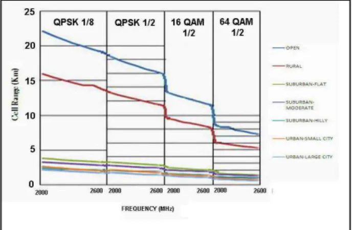
그림 3. 주파수의 그래픽 표현 대 다운 링크 셀 범위 Fig. 3. Graphical representation of Frequency Vs
Cell-range for downlink.
그림 4. 주파수의 그래픽 표현 대 업 링크 셀 범위 Fig. 4. Graphical representation of Frequency Vs
Cell-range for uplink
Ⅴ. Result and discussions
In Figure 3 Cell range gradually decreases as frequency increases and for adaptive modulation cell range decreases significantly, incase of downlink. Whereas for uplink Fig. 4 shows that, cell range decreases with the increases of frequency and so for adaptive modulation and it decreases significantly at 64 QAM 1/2 modulations. Study of cell range vs. base height found that cell range increases with increase of base height but as adaptive modulation advances cell range decreases for downlink.
The characteristic was found same for uplink too. Similarly, for downlink cell range increases with the change of power per antenna but with the advance of adaptive modulation cell range decreases. For both downlink and uplink, change of cell range with SNR was studied with different SNR ranges taken accoding to different modulation scheme and found that as SNR increases cell range decreases and so for adaptive modulation. For uplink, cell range decreases significantly at 16 QAM 1/2 modulation.
Ⅵ. Result and discussions
Adaptive modulation provides very large coverage area to WiMAX decreasing the density of BTS (Base-Transceiver Station) in a region. As it has seen WiMAX can serve this facility to open and rural areas more than urban and suburban locality.
This is a drawback of WiMAX because generally mobile subscriber density is greater in urban and sub-urban areas more than rural and flat areas. WiMAX is a very promising and advanced communication technology with some challenges like installation cost and performance. The betterment of performance avoiding these drawbacks creates further research scopes for future.
Reference
[1] WiMax: www.wimaxforum.org
[2] F. Rayal,“Combining Fixed and Mobile WiMAX Networks-Sup porting the Advance Communication Service of Tomorrow”
WiMAX White Paper, Redline Communication Inc., pp. 2-7.
[3] M. S. Baig, “Signal Processing Requirments for WiMAX (802.
16) Base Station”, Signal Processing Group, Department of Signals and Systems, Chalmers University, pp.46-57,2005.
[4] C. A. Balanis, Antenna Theory: Analysis and Design, second ed.
New York, NY: John Wiley & Sons Inc. 1997.
[5] M. C. Lax, A. Dammandar, “WiMAX - A Study of Mobility and a MAC Layer Implementation in GloMoSim” Umea University Department of Computing Science, pp. 1-99, 2006.
[6] Mobile WiMAX Part-I – A Technical Overview and Performance Evaluation Provided By-WiMAX Forum, August 2006.
Available: http://www.wimaxforum.org/news/downloads/Mob ile_WiMAX_Part1_Overview_and_Performance.pdf
[7] J. G. Andrews, A. Ghosh, R. Muhamed, Fundamentals of Wi MAX-Understanding Broadband Wireless Networking, New Jersey, NJ: Prentice Hall, 2007.
[8] Orthogonal Frequency Division Multiplexing [Internet].
Available: http://flylib.com/books/en/4.136.1.34/1/
[9] Link adaptation - Wikipedia [Online].
Available: http://en.wikipedia.org/wiki/Link_adaptation [10] F. Ohrtman, WiMAX handbook-Building 802.16 Wireless Netw
ork , New York, NY: McGraw-Hill, 2005.
Olly Roy Chowdhury
2006: Applied Physics Electronics and Communication Engineering,University of Dhaka, Bangladesh.(BS) 2007: Applied Physics Electronics and Communication Engineering,University of Dhaka, Bangladesh.(MS) Present – Lecturer, Department of Physics and Mechanical Engineering, in Patuakhali Science and Technology
University, Bangladesh. Currently, she is a PhD student in Sunchon National University.
Interests: Information and Communication Technology, Renewable Energy Harvesting.
Arif Kaiser Ongkon
2006: Applied Physics Electronics and Communication Engineering,University of Dhaka, Bangladesh.(BS) 2007: Applied Physics Electronics and Communication Engineering,University of Dhaka, Bangladesh.(MS) Present – Lecturer of Physics, Madargonj A. H. Z. Government College, Jamalpur, Bangladesh.
Interests: Information and Communication Technology.
Ekramul Kabir
2006: Applied Physics Electronics and Communication Engineering,University of Dhaka, Bangladesh.(BS) 2007: Applied Physics Electronics and Communication Engineering,University of Dhaka, Bangladesh.(MS) Present – Asst. Professor, Dept of Electronics & Communication Engineering, University of Information Technology
& Sciences (UITS), Bangladesh.
Interests: Biomedical engineering, Image processing, Signal processing, Communication Engineering etc.
Jang-woo Park
1987: Electronic engineering from Hanyang University, Seoul, Korea (BS) 1989: Electronic engineering from Hanyang University, Seoul, Korea (MS) 1993: Ph.D in Electronic engineering from Hanyang University, Seoul, Korea
Present – Professor, Department of Information & Communication engineering, Sunchon National University, Korea Interests: Localization and SoC and system designs and RFID/USN technologies.
SUBRATA KUMAR ADITYA
1981: Applied Physics Electronics and Communication Engineering,University of Dhaka, Bangladesh.(BS) 1982: Applied Physics Electronics and Communication Engineering,University of Dhaka, Bangladesh.(MS) 2001: Ph.D in Electical Engineering, Indian Institute of Technology, Kharagpur, India.
Present - Professor, Dept of Applied Physics Electronics and Communication Engineering, University of Dhaka, Bangladesh.
Interests: Intelligent System Engineering, Wireless and Mobile Communication, Renewable Energy Technology.
![그림 1. A 64-QAM 관계도 [7]](https://thumb-ap.123doks.com/thumbv2/123dokinfo/5194557.351824/2.892.462.769.775.1015/그림-a-qam-관계도.webp)
![Fig. 2. Time and frequency representation of the SC and OFDM. In OFDM, N data symbols are transmitted simultaneously on N orthogonal subcarriers [8]](https://thumb-ap.123doks.com/thumbv2/123dokinfo/5194557.351824/3.892.457.806.153.688/time-frequency-representation-symbols-transmitted-simultaneously-orthogonal-subcarriers.webp)