위치추정을 위한 인공표식 설계 및 인식
Artificial Landmark Design and Recognition for Localization
김 시 용1, 이 수 용2, 송 재 복3
Si-Yong Kim1, Sooyong Lee2, Jae-Bok Song3
Abstract To achieve autonomous mobile robot navigation, accurate localization technique is the fundamental issue that should be addressed. In augmented reality, the position of a user is required for location-based services. This paper presents indoor localization using infrared reflective artificial landmarks. In order to minimize the disturbance to the user and to provide the ease of installation, the passive landmarks are used. The landmarks are made of coated film which reflects the infrared light efficiently. Infrared light is not visible, but the camera can capture the reflected infrared light. Once the artificial landmark is identified, the camera’s relative position/orientation is estimated with respect to the landmark. In order to reduce the number of the required artificial landmarks for a given environment, the pan/tilt mechanism is developed together with the distortion correction algorithm.
Keywords : Localization, Artificial Landmark
1. Introduction
Mobile robots are being used to perform various tasks.
Localization is one of the essential functions required for the mobile robot. A lot of work has been done for last decades in order to get precise estimation of the location.
The augmented reality technique which merges the real and the virtual worlds has received a great deal of attention for displaying location-based information in the real world. To realize an augmented reality system, the exact position and orientation of a user are required.
Especially in indoor environments, since a GPS can not be used, many localization methods have been proposed.
[1] used several RF beacons for localization which requires only distance measurement. This method enabled accurate estimation of the robot configuration using the Markovian probability grids and the known
beacon locations. Similarly, [2] used RF networks for tracking users’ indoor movements. The signal strength is the key information used for localization. Both empirical and theoretical estimation of the signal strength related the distance information. [3] developed low priced localization support system using both RF signals and ultrasonic distance measurement. The proposed system measures the time difference between the RF signal and the ultrasonic sound and calculates the distance, thereby estimates the location with several beacons. A 3-D location system in which the Infrared marks and head-mounted stereo cameras are used for estimating the user location and the direction sensor provided the moving direction is introduced in [5]. In [6]
the embedded sensors and wearable cameras are used for self localization. Using several sensors including the inertial sensors, RFID tags, IrDA markers helped measurement of user location in [7]. New method of using invisible marks and infrared cameras for localization is described in [8].
In this paper, we developed the localization system using artificial landmarks. The infrared light reflecting landmarks together with infrared camera helped reducing the disturbance to the users and enabled simple
※ 본 연구는 산업자원부 지원으로 수행하는 21 세기 프론티어 연구개발사업(인간기능 생활지원 지능로봇 기술개발사업)의 일환으로 수행되었음.
1 홍익대학교 기계공학과 석사과정
2 홍익대학교 기계시스템디자인공학과 부교수
3 고려대학교 기계공학과 교수
installation. The landmarks are installed on the ceilings and made of films coated with infrared light reflecting material. A CMOS camera with USB interface is used for identifying the landmarks. In order to reduce the number of required landmarks, the camera is mounted on the pan/tilt mechanism so that less number of landmarks is used. A correction algorithm for image distortion due to the pan/tilt movement is developed.
2. Artificial Landmarks and Identification of the Landmarks
The artificial landmarks are made with the infrared light reflecting materials and the transparent film. It is required that the landmarks to be invisible to human and installation to be simple without any external power. A landmark is a right-angled equilateral triangle as shown in Fig. 1.
The landmark is partitioned as shown in Fig.2 for unique identification.
The three corner sectors (blue) in Fig. 1 are for estimation of the orientation. Those sectors are coated with infrared light reflecting materials and always reflect the infrared light illuminated. Because the size of the landmark is known, the landmark is easily recognized by these three sectors. The inner 6 six sectors (yellow) are for identification. Each of the sectors is either coated (reflection) or not (no reflection). Therefore, total number of 64 (=26) unique IDs (identifications) are available.
Fig. 1. Artificial Landmark (unit: [mm])
Fig. 2. Partitioned Artificial Landmark
Fig. 3–(a). Landmark with LED ON
Fig. 3–(b). Landmark with LED OFF
Fig. 3–(c). Difference Image of Fig.3-(a) & (b)
In case more than one artificial landmark is required for the given environment (which usually occur), then each landmark is designed for unique ID; the landmark in Fig.
1 has sectors 1, 3 and 6 coated.
In order to avoid the influence of other lights, infrared LEDs are flashed on and off continuously. The landmarks are robustly extracted from the difference between images with LED on and off. The position/orientation of the landmarks can be estimated without external power supply to the landmark and undesired visual effects in the real scene. Fig.3-(a) shows the landmark with infrared LED on. The landmark shown in Fig.3 has sectors 2, 3 and 5 coated. Fig.3-(b) is with infrared LED off and the difference image is shown in Fig.-(c).
Fig. 4. Camera with Infrared LEDs
A CMOS camera for PC (VX-6000 from Microsoft) is used for image capture. In order to clearly differentiate the existence of infrared light reflection, 40 infrared
Fig. 5–(a). Landmarks with IR LED ON
Fig. 5–(b). Landmarks with IR LED OFF
Fig. 5–(c). Difference Image
LEDs are installed around the camera for illumination as shown in Fig. 4.
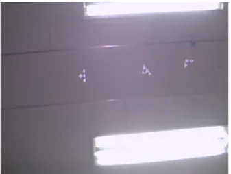
The artificial landmarks are installed on the ceiling.
Because two successive images are captured with and without the infrared illumination and the difference image is used, the artificial landmark(s) are robustly recognized even with nearby electric lights. Three landmarks (each has unique identification) are installed in-between fluorescent lamps as shown in Fig. 5.
Noises in the difference image are easily removed because the size and shape of landmarks are known.
The area of each white region is useful information for filtering out the noises. Also the extremity pixels are inspected whether it belongs to the right-angled equilateral triangle. Fig. 6 shows one recognized landmark.
All the corner pixels are identified and three of them (green circles in Fig. 7) which give the maximum area of the triangle, are recognized as three apexes of the triangle.
The longest side of the triangle is then identified and the line (blue line in Fig. 8) perpendicular to the base and passing the mass center (green circle in Fig. 8) of the triangle defines the orientation.
Fig. 6. Recognized Landmark
Fig. 7. Corners of the Triangle
Fig. 8. Mass Center and Orientation of the Triangle
Fig. 9. Identified Inside Sectors
Fig. 10. Recognized Landmarks
Then, the sectors inside the triangle are checked for identification. Three inside sectors (yellow sectors in Fig.
9) are identified in the recognized landmark, which is 1,3,5.
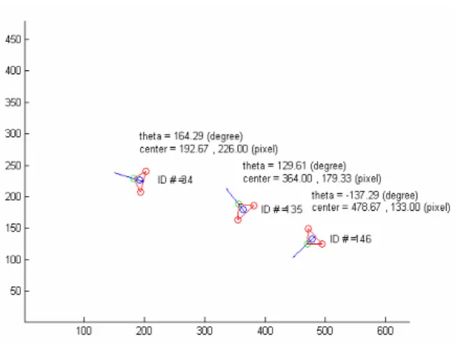
By repeating the same procedure, all three landmarks are recognized as shown in Fig. 10. Position of the center of mass and orientation of each landmark is estimated in Fig. 11. Note that the direction of the y axis in fig. 11 is opposite to the one in Fig. 10.
The relative location and orientation with respect to the landmark is estimated. If there are more than one landmark is used, the ID of the landmark is also
Fig. 11. Estimated Position/Orientation of the Landmarks
identified. The landmarks are installed by the user and their absolute locations/orientations are known a priori.
Therefore, the absolute position/orientation of the camera is estimated.
3. Camera Pan/Tilt
The size of the area the camera can capture is about 2.5m x 2.1m when the distance between the camera and the ceiling is 2.2m. Thus, with this information, the number of required artificial landmarks is calculated for the given environment considering that at least one landmark should be included in the image. In order to decrease the number of the artificial landmarks, pan/tilt motion is given to the camera (Fig. 12) and 8 additional images are available for localization..
The area of the sum of the 9 images is approximately 7 times larger than that of an image without pan/tilt. (Table 1), hence less number of landmarks is needed.
Fig. 12. Pan/Tilt Mechanism
Table 1. Area Increase with Pan/Tilt
Width
(cm)
Height (cm)
Area (cm
2) Normal Image 250 210 52,500 With Pan/tilt 740 490 362,600 The image is distorted once the camera is rotated, and it is required to correct the distortion before the recognition and identification of the artificial landmark is made. For correction, the Kinematic relation is derived between the global coordinates and the camera coordinates.
θ
xθ
yd
1d
2( ) a
+f
X
0Y
0Z
0X
5Y
5Z
5Fig. 13. Coordinates
d
1= distance between the origin and the θ axis
xd
2= distance between θ axis and
xθ axis
yθ = rotation along
xX
1axis
θ = rotation along
yY
3axis
a = distance between the CMOS surface and θ
yaxis
f = focal length m = width of CMOS n = height of CMOS
_
x pixel = pixel value on the image _
y pixel = pixel value on the image
0
cos
y 5sin
y 5( ) sin
yx = θ x + θ z + a + f θ (1)
0
sin
xsin
y 5cos
x 5sin
xcos
y 5y = θ θ x + θ y − θ θ z
( a f ) sin θ
xcos θ
yd
2sin θ
x− + − (2)
0
cos
xsin
y 5sin
x 5cos
xcos
y 5z = − θ θ x + θ y + θ θ z
2 1
( a f ) cos θ
xcos θ
yd cos θ x d
+ + + + (3)
Then, the coordinates of a pixel is represented as
_
i
1280
m x pixel
x ×
= (4)
_
i
1024
n y pixel
y ×
= (5)
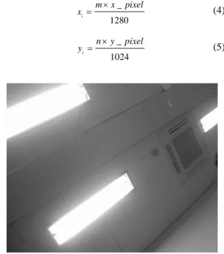
Fig. 14. Distorted Image
Fig. 15. Corrected Image
5 5
x z
ix f
= − ⋅ (6)
5 5
y
iz y
f
= − ⋅ (7)
0 2 1
5
{( ) cos cos cos } cos sin sin cos cos
x y x
i i
x y x x y
z a f d d
z x y
f f
θ θ θ
θ θ θ θ θ
− + + +
=
− +
(8)
Hence the location of any pixel on an image with respect to the global coordinates is
5
0
x
iz cos
y 5sin
y( ) sin
yx z a f
f θ θ θ
= − ⋅ + + + (9)
5 5
0
x z
isin
xsin
yy z
icos
x 5sin
xcos
yy z
f f
θ θ θ θ θ
⋅ ⋅
= − − −
( a f ) sin θ
xcos θ
yd
2sin θ
x− + − (10)
Figs. 14, 15 show the corrected images when the camera is rotated with θ = −
x30
oand θ
y= 30
o.
4. Experiment
With the pan/tilt unit, the 9 neighbor images are taken as shown in Fig. 16. All the images except the center one are distorted and the corrected images are stitched in Fig. 17.
Estimations of the position and orientation are done at several locations. Eight positions are selected where the
Fig. 16. Distorted Images
Fig. 17. Corrected Images
Table 2. Localization Results
Actual
(x[cm],y[cm],θ[°])
Estimated
(x[cm],y[cm] ,θ[°]) A (-330,240,180) (-336,238,182) B (0,240,180) (1,243,182) C (330,240,180) (328,244,188) D (330,0,180) (332,2,174) E (330,-240,180) (335,-233,171) F (0,-240,180) (-2,-245,176) G (-330,-240,180) (-334,-241,182) H (-330,0,180) (-332,3,186)
accuracy is expected to be relatively low. Localization results are summarized in Table 2.
5. Conclusion
![Fig. 1. Artificial Landmark (unit: [mm])](https://thumb-ap.123doks.com/thumbv2/123dokinfo/5337867.393396/2.892.543.720.148.241/fig-artificial-landmark-unit-mm.webp)
![Table 2. Localization Results Actual (x[cm],y[cm],θ[°]) Estimated (x[cm],y[cm] ,θ[°]) A (-330,240,180) (-336,238,182) B (0,240,180) (1,243,182) C (330,240,180) (328,244,188) D (330,0,180) (332,2,174) E (330,-240,180) (335,-233,171) F (0,-240,180)](https://thumb-ap.123doks.com/thumbv2/123dokinfo/5337867.393396/6.892.465.795.486.693/table-localization-results-actual-cm-cm-θ-estimated.webp)
