1. INTRODUCTION
Recently, smartphones that have entered the market are comparable to desktops in terms of graphics processing and computation speed enough to play high quality graphic
games. In addition, the specification of the camera mounted on the smartphone has 12x106 pixels in the case of the latest phone, and size of the pixel is generally 1.4 μm and the size of the image sensor is 1 / 2.55 in.
Accordingly, varieties of applications using
모바일 폰을 이용한 스마트 E-캘리퍼스 구현
윤한경*
An Implementation of Smart E-Calipers for Mobile Phones
Han-Kyung Yun*
요 약 스마트폰의 고성능 카메라를 사용하여 버니어 캘리퍼스를 대체할 앱의 개발을 목표로 연구를 진행하고 있다. 앱 은 제안된 템플릿이 부착된 측정 대상을 촬영한다. 촬영된 영상에서 템플릿을 참조하여 측정 대상에서 사용자가 지정한 지점 간의 거리를 측정한다. 앱의 정밀도는 시중에서 판매되고 있는 버니어 캘리퍼스의 오차 범위를 유지하도록 한다. 시 장에 보급된 스마트폰의 카메라는 12M 픽셀이며, 그 이미지 셀의 크기는 1.4μm이므로 이론적으로 버니어 캘리퍼스보다 더 정밀한 측정이 가능하다. 기존에 제안한 알고리즘에서는 촬영된 소스 영상의 템플릿 형태로부터 기준 거리를 추출하였 지만, 제안하는 알고리즘은 알고 있는 템플릿의 기하학적 속성을 이용하여 영상을 보정한 후 거리를 구함으로써 향상된 정밀한 길이를 구할 수 있다.
Abstract The study is underway with the goal of developing an app that will replace vernier calipers using a smartphone's high-performance camera. The specifications of the camera mounted on recent smart phones have evolved so that usually has a 12 Mpixels of image sensor and its size of the pixel is 1.4㎛ and the size of the image sensor is 1 / 2.55 in. The proposed algorithm will apply to develop a precision measuring application that will compete with the Vernier calipers. Most existing applications cannot guarantee an accuracy in scale because the scale of the ruler displayed on the image is unclear or the size of the measurement object varies depending on the distance between the camera and the measurement object. In addition, another accurate measuring tools using lasers are also available, but they are limited because they are expensive. Therefore, if easy-to-carry and precise applications are developed, it is possible to substitute existing measurement tools. The proposed correction algorithm is an algorithm that automatically corrects the distorted source image using the shape and size information of the known template. The e-calipers are applications that display the distance when the area to be measured is specified in the corrected image.
Key Words : edge extraction, geometric attribute, length measuring, square template, e-calipers
This Paper was supported by Research Promotion Fund of Korea University of Technology and Education in 2019.
*School of Computer Science and Engineering, Korea University of Technology and Education Received July 29, 2020 Revised August 21, 2020 Accepted August 23, 2020
cameras have been developing and the application area thereof has been greatly expanded. The applications for measuring the lengths already announced are mostly measuring the length of an object by displaying a scale, and there are limitations in precision measurement. There is also a precision measuring tool for measuring the distance and length, but it is not easy to handle and expensive to use. Traditionally, Vernier calipers have been used for accurate length measurement in industrial areas, and calipers have also been developed in various forms and used depending on the objects or parts to be measured. In addition, it is inconvenient to carry without using a specially designed carrying case. In order to measure a specific area in a limited space such as a car center fascia, precise measurement may be difficult due to the shape and structure of the calipers. In other words, it is impossible or inconvenient to measure the length with a calipers in some cases. On the other hand, most people have smartphones regardless of their will.
Therefore, if a smartphone can used as a measuring tool, it is possible to measure the length without having a separate measurement tool. In addition, if the captured source image can be stored, batch measurement can be performed at once.
Furthermore, if the measurement result can be stored together with the measurement image, convenience of using all measurement results without additional memo can be secured. The advantages and benefits mentioned above are that the measurement results must remain accurate enough to compete with the calipers to maximize the
ripple effect of the e-calipers application.
The problem is that the distance between the subject and the camera is arbitrary and it is never easy to keep the subject's face exactly parallel to the camera's sensor face.
Therefore, we decided to correct the distortion of the image with template.
2. CORRECTION ALGORITHM
2.1 Distance measurement application Conventional algorithms are mainly used to project a given image to a natural image in accordance with external phenomena in consideration of the influence of external force or lens characteristic. An algorithm for manually specifying a position to correct a distorted image has also been developed, which is used for distortion correction[6].
There are many applications in the current market as shown in Fig. 1. Many ruler applications imitate a typical ruler that measures the length of an object by displaying a scale. Another measurement application is to measure the size of an object using sensors built into the smartphone or using an auxiliary device such as a laser generating devices.
Fig. 1. Length measuring app. (From google image[4])
The former two methods are less accurate and cannot be used for precise measurement.
The use of ancillary instruments can improve precision, but they are less competitive in terms of portability and cost. Therefore, if
low-cost applications that can measure relatively short lengths and compete with calipers for accuracy and tolerance range are developed, then no user would be willing to inconvenience the Vernier calipers. In addition, it is possible to measure at any place where shooting is possible and to add the function to store the measured data digitally, it can maximize user convenience.
The auto correction algorithm proposed in this study uses a template attached to a subject in shooting a measurement object in order to maintain precision like an application using an existing auxiliary device. The purpose of the template is to correct the distortion of the original image.
The template should be developed in various forms according to the measurement site and purpose, thereby reducing the error and improving the accuracy. However, the template developed in the first place has a square shape of the two-dimensional geometry. In addition, by limiting the size of the template to less than the size of the credit card, the convenience of the user is considered by making it possible to store it in a smartphone case that can store a card frequently used by users recently.
2.2 Template for auto correction
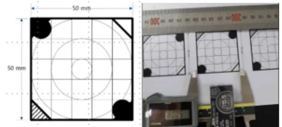
The template [Fig. 2] provides information necessary for correcting the source image so that the image sensor surface of the smartphone camera is parallel to the subject surface, and measures the length of the subject in the image by applying the dimension of the template provided in the corrected image to the length of the real world. Therefore, the more precise the measurement can be made as
the shooting environment is created so that the template can be simply attached to the surface of the object to be measured and the measurement plane and the template are parallel.
Fig. 2. Template used for the proposed algorithm
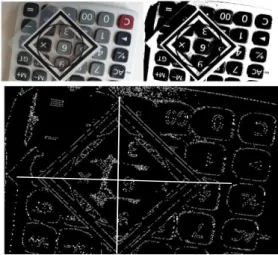
2.3 Corrected image extracted and results 2.3.1 Edge detection of the template Even if images are acquired with care, the square template almost distorted when viewed in units of pixels having a size of 1.4µm, and the template is inevitably deformed due to restriction of the shooting space. Therefore, the template must be extracted by searching the photographed source image. For this purpose, the source image is transformed into a monochrome binary image and the threshold value is used to minimize the intra-class variance of the black and white pixels proposed by Otsu [1]. The binary image is transformed into a closed image by performing morphological operation using disk (circular) approximation method and morphological closing operation to minimize unnecessary operation when performing boundary detection. Fig. 3 shows the result of logically searching a template by grouping regions having the same pixel values in a binary image, which is a pixel-by-pixel matrix. Observing the vertices of the
template in the figure below shows that the corresponding vertices are not orthogonal.
This means that the source image is distorted. This is the same phenomenon that the projector's image and screen are not parallel. Therefore, the template can be easily attached to the surface of the object to be measured, so that accurate measurement can be made when the shooting environment is created such that the object surface and the template are parallel.
Fig. 3. Source image(top-left), Binary image(top-right), Edge detected image(bottom)
2.3.2 Reading 4 vertexes and extracting its corresponding vertex
In other words, it can be corrected using a 2D projective transformation, which is often used to register unaligned images [2, 3]. In order to apply the Holography matrix for the 2D projection transformation, the goal of this paper is to extract the four coordinates of the template vertices extracted from the image and the correction vertex corresponding to each vertex.
2.3.2 Reading 4 vertexes and extracting its corresponding vertex
The template can be easily attached to the surface of the object to be measured, so that accurate measurement can be made when the shooting environment is created such that the object surface and the template are parallel. The distorted square template means that the sensor plane and the object plane are not parallel, and can be corrected with 4points 2D projection applying spatial rotation and displacement. For correction, we need to obtain the coordinates of four vertices in the extracted template image.
Coordinate values search the vertex coordinates by making the inner surface of the template’s edge black and the background white. However, considering execution speed and computation amount, we only cropped the template region and minimized the amount of computation by applying window to include vertex with clockwise direction as shown in Fig. 4. Fig. 5 is a graph showing the four vertices of the cropped template and their corresponding corrected vertices (*) using the suggested algorithm [5, 6].
Fig. 4. Cropped template and 4 vertices
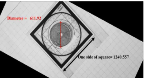
When the proposed algorithm is performed, the length of one side of the template is
1240.557 pixels, which is 50mm, so it is 24.81 pixel/mm. Therefore, when the diameter of the coin is measured, the average is 606.93 pixel, which is 24.46mm, but a measured value of a calipers was 24.48mm as shown in Fig. 7 and the measured range of calipers was 24.45~ 25.52mm.
Fig. 5. Extracted template, mapping points(*), and its center(o)
The template in Fig.4 shows that the source image template distorted by a square of 50mm on the side of the real world. Since the corrected template image is exactly on the straight line with the non-neighboring vertex, the distance between the two points in the image is can be measured.
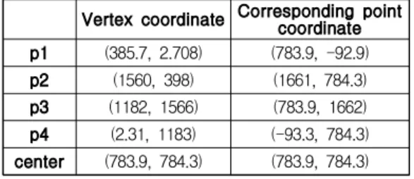
Table 1. Template coordinate points and its center Vertex coordinate Corresponding pointcoordinate p1 (385.7, 2.708) (783.9, -92.9) p2 (1560, 398) (1661, 784.3) p3 (1182, 1566) (783.9, 1662) p4 (2.31, 1183) (-93.3, 784.3) center (783.9, 784.3) (783.9, 784.3)
As shown in Fig. 5, it is possible to apply the 4-point 2D projection because the
corresponding four vertices can be obtained by correcting the template of the distorted image obtained using the proposed algorithm. The data of four vertices shows in Table 1.
3. Result and Analysis
In comparison between Table 1 and Fig. 5, it can be seen that there is a complex relationship between rotation and linear movement between the vertices of source image and the corresponding matching point. This is because the camera sensor surface is not parallel to the surface but tilted to be. Thus, as mentioned earlier, correction can be done using a 2D projective transformation using 4-points method, which is often used to register an unaligned image.
The relationship between the vertex coordinates of the template in the source image and the corresponding vertexes derived by the proposed algorithm is represented by a Homography matrix (H) as shown in (1), so that a Homography matrix can be obtained. Where P is the corresponding vertex matrix and P' is the coordinates of the template obtained from the source. If the Homography matrix (H) applies to the source image, Fig. 6 is obtained.
(1)
where H is
Fig. 6. Corrected Image from source image and one of measured data
Table 2. Measured results
Diameter of coin
[pixel] [mm]
1 604.88860 24.37887
2 603.27630 24.31389
3 608.43580 24.52184
4 605.91070 24.42007
5 612.12610 24.67057
6 611.92150 24.66232
Average 606.92750 24.46105
4. Conclusion
What should be improved through further study is the development of a more precise template than the prototype used. In order to minimize the influence on the surrounding light, the color of the template should be matted to minimize reflection. The first thing to be careful about is that the template should be parallel to the subject's face, and the second is to obtain the image at the minimum distance from which the image can be obtained, if possible. If the two conditions described are met, the measurement result is theoretically possible for an e-calipers application with higher resolution than the Vernier Calipers.
Fig. 7. A measured diameter of coin with a calipers
Additionally, the proposed of the application is to develop a function to recognize automatically the measuring point by searching the boundary, and to design and implement a user-oriented user interface, to be stored the measurement results including images, then our application will compete with the Vernier calipers.
REFERENCES
[1] Otsu, N., "A Threshold Selection Method fro m Gray-Level Histograms," IEEE Transactions on Systems, Man, and Cybernetics, Vol. 9, N o. 1, 1979, pp. 62-66.
[2] Goshtasby, Ardeshir, "Piecewise linear mappi ng functions for image registration," Pattern Recognition, Vol. 19, 1986, pp. 459-466.
[3] Goshtasby, Ardeshir, "Image registration by l ocal approximation methods," Image and Vis ion Computing, Vol. 6, 1988, pp. 255-261.
[4] https://www.google.com/ image
[5] Sun-Min Hwang, Han-Kyung Yun, “An Impr oved Smart Correction Algorithm for a Disto rted Image”, The 5th Int. Conference on Inf ormation, Electronics, and Communication T echnology, pp 38-44, 2019
[6] Sun-Min Hwang, Han-Kyung Yun, “An Impr oved Smart Correction Algorithm for a Disto rted Image”, The 5th Int. Conference on Inf ormation, Electronics, and Communication T echnology, pp 38-44, 2019
[7] Sun-Min Hwang, Han-Kyung Yun, “A Smart Correction Algorithm for Distorted Image”, 2
019 Spring Conference Proceeding on Infor mation, Electronics, and Communication Tec hnology, Vol. 12 No. 1, pp22-24, 2019
저자약력
윤 한 경(Han-Kyung Yun) [종신회원]
• 컴퓨터공학부 한국기술교육대학교 교수
<관심분야> 인공지능, IT 융합, 컴퓨터 응용
![Fig. 1. Length measuring app. (From google image[4])](https://thumb-ap.123doks.com/thumbv2/123dokinfo/5314943.384024/2.892.463.752.814.889/fig-length-measuring-app-from-google-image.webp)