Vol. 19, No. 1, pp. 31-37, February 2015
Force Control of 6-DOF Pneumatic Joystick
Yoshito Tanaka*†, Yasunobu Hitaka**, So-Nam Yun***, Ji-U Kim***, Eun-A Jeong***, Jung-Ho Park*** and Young-Bog Ham***
(Received 16 September 2014, Revised 08 January 2015, Accepted 20 January 2015)
Abstract: In this paper, it is presented the development of a new type force feedback system. It is based on a 6-DOF Stewart parallel mechanism1,2) which has six pneumatic actuated cylinders. The thrust force of each cylinder is controlled by PWM control for the solenoid valve and it is actualized by PIC controller. When the pneumatic actuator is controlled, it must be considered the influence on the compressibility of air. For this problem, we guarantee the control characteristics by the effect of the accumulator. It is confirmed that the thrust force of the cylinder can be applied to the pneumatic parallel mechanism, and is presented the experimental result of force control for vertical direction.
Key Words:Parallel Manipulator, 6-DOF, Force Control, Pneumatic Control, PIC, PWM, OpenGL
*†Yoshito Tanaka(corresponding author) : Korea Brain Pool Researcher, Korea Institute of Machinery & Materials.
E-mail : [email protected], Tel : 042-868-7053
**Yasunobu Hitaka : Department of Control and Information Engineering , Kitakyusyu National College Technology.
***So-Nam Yun, Ji-Woo Kim, Eun-A Jeong, Jung-Ho Park, Young-Bog Ham : Department of Extreme Energy Systems, Korea Institute of Machinery & Materials,
― Nomenclature ―
x, y, z : Translational motion [m]
F : Thrust Force [N]
P : Pressure [MPa]
A :Area of cylinder [m2]
Greek Symbols
φ , θ, ψ : Rotational motion [rad]
τ : Modulation Rate η : Load factor
1. Introduction
For the patients afflicted with paralysis, the rehabilitation aid by the physical therap is tisnecessary. In recent years, the number of the paralyzed patients is increasing due to some reasons, like the adult disease, traffic accident and aging, and the shortage of the physical therapist becomes a new social problem. Thus, it is required the rehabilitation support technology. Corresponding to the patients with various paralysis symptoms, it is necessary for the rehabilitation equipment to support the multiple degrees of freedom movement3,4) ,5).
We note the Stewart type parallel mechanism and consider applying it to the rehabilitation equipment for the wrist or hand paralysis. This mechanism achieves 6-DOF motion and has two characteristics that are high power and high rigidity. Therefore, it is useful for the wrist or hand rehabilitation equipment. The multiple motion of this mechanism can be achieved by the coordinated telescopic motion of six actuated cylinders. The power source of the cylinder is hydraulic pressure, pneumatic or
servomotor. We choose the pneumatic cylinder since this actuator has a flexible characteristics due to the compaction property of the air and therefore it actualizes friendly and soft rehabilitation aid for the patients.
In this paper, it is presented the development of the force feedback system which generates the feedback force through the pneumatic parallel mechanism. This system will be a base technology of the rehabilitation equipment for the wrist or hand paralysis. The pneumatic parallel mechanism is designed by 3D-CAD and made a prototype model.
Control of the thrust force of each pneumatic cylinder is actualized by PWM control for the solenoid valve. The PIC is used to the controller for the PWM control. When the pneumatic actuator is controlled, it must be considered the influence on the compressibility of air. For this problem, the control characteristics are guaranteed by the effect of the accumulator.
This paper consists of seven sections. This section is introduction. Next section presents the property of the Stewart type of parallel mechanism with comparing the commonly known the serial mechanism. 3rd section shows the configuration of the force feedback system. In 4th section, the design of the parallel mechanism and developed prototype model are presented.
The detail of force control of the pneumatic cylinder is denoted in section 5. In section 6, the result of the force control experiment for unit cylinder is presented. And then, for the parallel mechanism which has the six cylinders, the experimental results for vertical direction motion are presented.
2. Structure of parallel mechanism
In the multi degrees of freedom motion
mechanism, there are the Stewart type parallel mechanism and the commonly known serial mechanism in robot. The parallel mechanism consists of a bottom base, upper plate which is called “platform” and six telescopic cylinders. By the coordinated telescopic motion of each cylinder, the platform achieves 6-DOF motion. It has many advantages compared with the conventional serial link mechanism. They are:
• Higher payload-to-weight ratio since the payload is carried by six cylinders in parallel,
∙ Higher accuracy due to non-cumulative joint error,
∙ Higher structural rigidity,
∙ Simpler solution of the inverse kinematics equations.
Therefore, it is expected to be applied to flight simulator, medical robot, machining tool and so on.
On the other hand, this type manipulator suffers from smaller work space and complex structure.
3. System configuration
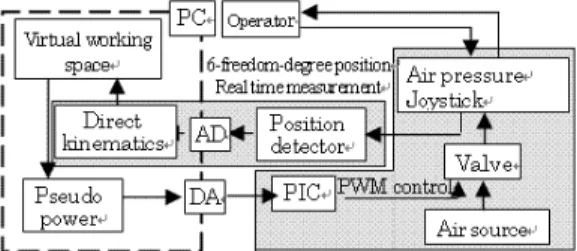
Figure 1 shows the configuration of the force feedback system in this research. It mainly consists of the pneumatic parallel mechanism and the personal computer. As shown in Fig.2, there is a gripper on the platform of the pneumatic parallel mechanism and it can be moved with 6-DOF by hand. Each cylinders of the parallel mechanism has a position detector and it detects the cylinder length. The PC calculates the attitude of the parallel mechanism by solving the direct kinematics of the parallel mechanism with the data of each cylinder length. From the calculation result, the PC draws a similar parallel mechanism which shows the harmonic motion with the real one in a virtual working space on the display. The virtual working space and the parallel mechanism in it are drawn by OpenGL architecture. When the parallel
Fig. 1 Configuration of force feedback system
Fig. 2 Pneumatic parallel mechanism with gripper on the platform
mechanism in the virtual space contacts some kind of obstacle as Fig.3, PC calculates the virtual reaction force and sends the control signals to the six PIC controllers, respectively. Each PIC controller controls two solenoid valves on one pneumatic cylinder of the parallel mechanism by PWM.
Fig. 3 Contact the obstacle in a virtual space
The one solenoid valve is used for the pushing force of the cylinder and the other is for the pulling force. The resultant force of six cylinders is
equivalent to the virtual reaction force. Then, the operator feels the reaction force generated in the virtual space at his hand.
4. Prototype model of the pneumatic parallel mechanism
In this section, a prototype model of the pneumatic parallel mechanism for the use of the force feedback system is presented. Figure 4 is the 3D-CAD design image of the prototype model.
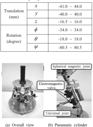
This mechanism has 6-DOF motion, namely, translational motion along x-axis (surge motion), y-axis (sway motion) and z-axis (heave motion), and rotational motion about x-axis (roll motion), y-axis (pitch motion) and z-axis (yaw motion). For the designed model, the working range is investigated by analyzing the inverse kinematics.
Table 1 shows the working range of 6-DOF. Figure 5 (a) is the overall view of the prototype model and (b) is close up of one of the pneumatic cylinders. It has a position detector and two solenoid valves. The bottom end of cylinder is connected to the bottom base by a universal joint.
The upper end of cylinder is connected to the platform by a spherical magnetic joint. The reason of using the magnetic joint for upper joint is that if unexpected huge force acts on gripper, the platform uncouples from the upper joints and therefore the destruction of the parallel mechanism is averted.
Fig. 4 3D-CAD image
Table 1 Working range
Translation (mm)
x
-41.0 ~ 44.0y
-40.0 ~ 40.0z
-16.5 ~ 16.0Rotation (degree)
-34.0 ~ 34.0
-18.0 ~ 18.0
-80.5 ~ 80.5(a) Overall view (b) Pneumatic cylinder Fig. 5 Prototype model
5. Force control of pneumatic cylinders
The force control of each pneumatic cylinder of the prototype model is actualized by regulating the supplied airflow. The airflow is regulated by PWM control for the solenoid valve. As shown in Fig.6, the PWM (Pulse Width Modulation) is a modulation method that is tuning ON time for the pulse wave at a constant cycle by changing the modulation rate. Where, let τ denotes the modulation rate,
denotes on constant cycle and
denotes ON time in
, τ is described as Ton
TFig. 6 PWM wave and Duty rate
By the PWM signal, opening-closing time of the solenoid valve is tuned, and thereby supplied airflow for pneumatic cylinder is regulated. Figure 7 (a) and (b) show turn-on and off of three-way solenoid valve, respectively.
(a) ON (b) OFF Fig. 7 Three way solenoid valve
Fig. 8 Control Circuit
Figure 8 is the circuit of the force control of the neumatic cylinders. The duty rate τ decided by PC is converted to analog signal (voltage) through the DA convertor. The analog signal is input into PIC controller. The PIC generates PWM signal and sends it to two solenoid valves. The one valve is
used for the pushing force of the cylinder and the other is for the pulling force. The relation between the average control pressure and the modulation rate τ of PWM is written as
2 2
(1 )
2p p
S
(1)where, sign
, is supply pressure. From Eq. (1), thrust force F of the cylinder is given by2 2
(1 )
2F Ap
S
(2)where, is an area of the pushing side or pulling side of the cylinder, and η is a load factor.
6. Experimental results
In this section, the experimental results of force control of the prototype of pneumatic parallel mechanism are presented. At first, the average control pressure for the change in the modulation rate τ of PWM is measured. Figure 9 is the overview of the experiment and Fig. 10 shows the result where the supply pressure is adjusted to 0.15MPa and the pipe length between the solenoid valve and the manometer sets 50mm.
Fig. 9 Measurement of air pressure
It shows the difference between the measurements and predictions by Eq.1. For the result, we try to improve the control performance by using the effect
Fig. 10 Pressure (pipe length 50mm)
Fig. 11 Pressure (pipe length 500mm)
of the accumulator. Figure 11 is the result where the pipe length between the solenoid valve and the manometer set 500mm to increase the accumulator.
As shown Fig. 13, the control performance is improved, and therefore it was known that when the volume between the solenoid valve and the cylinder is small, compressibility of air influences the pressure characteristic. And it is understood that the force characteristic is depend on the capacity of the accumulator.
Figure 12 is the overview of the experiment of the force control of single pneumatic cylinder. The load cell is set up between a fixed wall and the cylinder to measure the thrust force of the cylinder.
The supply pressure is adjusted to 0.15MPa.
Fig. 12 Experiments with a single cylinder
The results of measurements and predictions by Eq.2 are shown in Fig.13. It shows two forces. The one is the pushing force and the other is the pulling force. For both forces, the measurement values agree well with the predictions. The reason of the pulling force is smaller than the pushing force is that the area of the pulling side of cylinder is decreased since there is a rod on the surface of the piston.
Fig. 13 Cylinder force
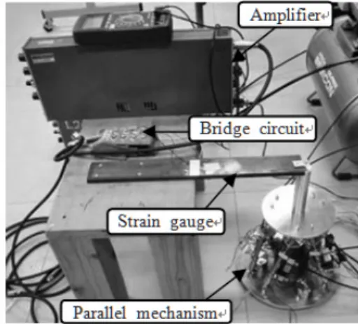
The thrust force of the pneumatic cylinder is controlled, and it supplies the force control pneumatic mechanism shown in Fig.1. The force sensor (0 ~ 100N) consists of the strain gauge, and the force in z-direction is measured. The same modulation rate is given for six cylinders, and the force of z a-axis is measured. Figure 14 is the overview of the experiment.
Fig. 14 Experiments with the parallel mechanism
Figure 15 shows the results of experiment. Where the posture is adjusted to be neutral position (cylinder expansion and contraction 15mm) and the supply pressure is 0.15Mpa. The calculated value is summation of each thrust force of 6 cylinders in vertical direction obtained thrust from Eq.2. The prediction agrees well with the measurements, and z-axis force control is possible. A force of approximate 60N is generated when the supply pressure is 0.15Mpa, and it has been understood the enough force experienced by man is generated.
Fig. 15 Force control of parallel mechanism
7. Conclusions
The prototype model of pneumatic parallel
mechanism for use of the force feedback system has been developed, and the 6-DOF force control was achieved.
The conclusion is shown below.
(1) The thrust force of the cylinder is generated by the PWM control of the solenoid valve. And the control characteristic of the thrust force of the cylinder was confirmed by the change in the amount of the cylinder expansion and contraction.
(2) The compressibility of air can be compensated with accumulator, and the control characteristic of the thrust force of the cylinder has been improved.
(3) The pneumatic 6-DOF parallel mechanism was developed. The push and pull z-axis force control in z-axis was evaluated by the experiment, and it was confirmed that the force control by the PWM control was possible.
Acknowledgement
This research was financially supported by the 2014 Brain Pool Program of the KOFST (MF054A).
References
1. D. Stewart, A Platform with 6 degrees of freedom, Proc. Inst. Mech. Eng., Vol. 180, Part I, No. 15, pp. 371-386, 1965-66.
2. L. W. Tsai, Robot Analysis, John Wiley &
Sons, Inc. pp. 116, 1999
3. M. Takaiwa, T. Noritsugu, Development of Human-Robot Haptic Interface Using Pneumatic Parallel Manipulator, Proc. 4th JHPS Int. Symp.
on Fluid Power, pp.181-186, 1999
4. Y. Tanaka, T. Nakajima, T. Sawada, Desktop Type of Force Display Using Pneumatic Parallel Mechanism, Proceedings of the Fourth International Symposium on Fluid Power Transmission and Control (ISFP’2003, Paper for
Plenary Session), pp. 267-271, April 2003 5. C. H. Kim, H. J. Jeong and J. H. Yang, The
Robust Servo Controller Design of Magnetic Levitation System Considering Pole Assignment Region, J. of KSPSE, Vol. 4, No. 4, pp. 84-91, 2000