논문 2011-48SP-6-13
기하학적 불변성을 이용한 새로운 렌즈 보정 기법
( A New Method Using Geometric Invariability for Lens Distortion Correction )
반 토안 카오*, 조 상 복*** ( Van-Toan Cao and Sang-Bock Cho )
요 약
일반적으로 실제 사용되는 카메라들은 렌즈 왜곡이 존재하며, 렌즈왜곡의 정도는 카메라의 가격뿐만 아니라 특정 용도에 의해 달라진다. 현재까지의 많은 렌즈 왜곡 보정기법들은 왜곡 변수를 찾기 위해 투영 기하학의 불변량 속성을 기반으로 한 것으로, “물 체의 직선은 이미지에서의 직선”이라는 상식에서 출발한다. 하지만, 평행선인 경우 이전의 연구들은 렌즈 왜곡 변수를 결정하는데 제약이 있다. 본 논문에서는 렌즈왜곡 변수를 결정할 때 동시에 평행선 유지를 보증할 수 있는 방법을 제안함으로써, 핀홀 카메라 모델을 이용하여 투영된 이미지와 실제 이미지가 근접한 결과를 얻게 된다. 실제 이미지와 제안된 기법을 사용한 보정이미지를 비교하여 그 효율성을 입증하였다.
Abstract
Most of cameras being used in practice induce lens distortion; the amount of distortion depends on the specific applications as well as the camera cost. Up to now, many methods of lens distortion correction have relied on invariant properties of projective geometry to find distortion parameters. A common property is “the straight line in scene is straight line in image”. However, if the straight lines are also parallel together, the previous works have missed this restriction in determining lens distortion parameters. In this paper, we propose a method that leads to guarantee of the restrictions simultaneously for the determination. Therefore, corrected image will close to an ideal image taken by the pinhole camera model. The effectiveness of the proposed method is verified by our experiments on both synthetic images and real images.
Keywords : lens distortion, radial distortion, distortion model, invariant
Ⅰ. Introduction
Lens distortion has been considerably treated in image processing. This is an inevitable physical phenomenon caused by spherical lens, as result in general camera. Finding and correcting lens distortion
* 학생회원 ** 정회원-교신저자, 울산대학교 전기공학부
(School of Electrical Engineering, University of Ulsan)
※ This work was supported by the University of Ulsan and Hyundai Heavy Industries for the Excellence of Education and Research.
접수일자: 2011년4월6일, 수정완료일: 2011년10월13일
are the essential preprocesses to achieve correct content of image for next steps. On the other hand, these steps generate final image with the least deformation from low cost camera lenses.
Model of lens distortion was proposed by Brown[1~
2] including radial distortion, decentering distortion and prism distortion. Radial distortion (barrel distortion or/and pincushion distortion) is noticeable and other distortions are acceptably negligible, as shown in Fig.1. The adopted methods to this model
[7~8, 11, 13~15, 18] used 3D reference points to find lens distortion parameters. These methods encountered in
(a) (b) (c)
그림 1. 방사형 왜곡 : (a)왜곡이 없는 이상적인 이미지 (b) 배럴 왜곡 (c) 오목 일그러짐
Fig. 1. Radial distortions: (a) Ideal image with no distortion. (b) Barrel distortion. (c) Pincushion distortion.
setting up experiments precisely and extracting control points accurately under noise impact. In another class of lens distortion correction, there have been many proposed methods based on geometric invariants of some features to achieve distortion parameters[3~4, 9~10, 12]. The straight property of line- the straight line in scene is straight line in image- is used widely. However, if the straight lines are also parallel together, these methods have missed this restriction in determining lens distortion parameters.
This can cause wrong distortion parameters of final solution in search algorithm. Finally, the other approaches were proposed to correct lens distortion that collect whole content of image to get distortion parameters[5, 16~17]. These approaches take advantage of image content without requiring any pattern calibration. However, results are still limited to lead to convincing results.
In this paper, our proposed method is based on invariant of the projective transformation “a straight line in a 3D scene domain is itself straight line in the 2D image domain”[2]. This means that curvature of lines in the image that should be straight is due only to lens distortion. Using this principal, iterative search algorithms are applied to seek adequate distortion parameters, which make cure lines in image become its original state – the straight lines.
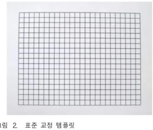
The proposed method in this paper is different from above works. We use a template consisting of lines that are straight, parallel and perpendicular together, as shown in Fig.2. After the correction, the r
그림 2. 표준 교정 템플릿
Fig. 2. Standard calibration template.
estrictions of lines of template are guaranteed.
This paper is organized as follows. Section Ⅱ describes lens distortion model and overview of our method. Detail of the proposed method is explained in section Ⅲ. Experimental results are reported to compare the proposed method with other methods in Section Ⅳ. Section Ⅴ concludes the paper.
Ⅱ. Lens distortion model
1. Lens distortion model
The standard model for the radial and decentering distortion is mapping from the distorted image coordinates that are observable to the undistorted image coordinates which are not physically measurable.
(1)
where and are coefficients of radial distortion and are coefficients of decentering distortion,
is the radius of an image point from the distortion center defined as above.
Typically, we only consider two coefficients of radial distortion[3, 10, 14, 18].
The model after discarding other terms:
(2) Therefore, the method for lens distortion correction is to seek the practically significant distortion coefficients , and distortion center .
2. Overview of our method
For a given template, as shown in Fig.2, it consists of straight lines (dark color) in horizontal and vertical directions. These lines are parallel and perpendicular together on bright background.
In horizontal direction, on a horizontal line that is the nearest to distortion center, we find out the intersection points of this horizontal line with vertical lines. Based on each intersection point, we count the number of pixels of vertical line which cross the intersection point. Because lens distortion exists, a number of pixels of the vertical line do not lie on vertical axis (origin of vertical axis is intersection point). We then measure the farthest distance among pixels of each line to vertical axis respectively at each base point and seek lens distortion parameters of camera by minimizing this distance. The process is the same for vertical direction. Fig.3 shows the position of pixels in horizontal direction of a non-distorted image and a distorted image.
Ⅲ. The proposed method
1. Explanation of the proposed method First of all, binary image is made of gray image.
In the binary image, there are horizontal lines and vertical lines and the width of these lines is one pixel. Then the distortion center is initialized, e.g.
image center.
In horizontal direction, because a straight line crossing the distortion center is still straight line in distorted image, so a horizontal line that is through the distortion center (or the nearest the distortion
Position of pixels (a)
Position of pixels (b) 그림 3. 수평 방향에 픽셀의 개수 :
(a) 비 왜곡된 이미지 (b) 왜곡된 이미지 Fig. 3. The number of pixels in horizontal direction:
(a) in non-distorted image. (b) in distorted image center) is chosen. This line is named driven line.
On the driven line, determine the points where vertical lines intersect with this line. These points are named base points. The number of the base points is equal the number of vertical lines .
Based on each base point, in next step, we count the number of pixels of respective vertical line. Due to lens distortion, a number of pixels of vertical line do not lie on vertical axis (the origin of vertical axis is base point). In the close range of each base point, we determine one point on the left and another one on the right of base point where the number of
그림 4. 올라가는 위치의 포인트 그리고 내려가는 위치 의 포인트 안에 왜곡된 이미지의 첫 번째 부분 수평 방향의 위치
Fig. 4. The position of up-position point and down-position point in horizontal direction of first part in distorted image.
pixels at these two points are greater than pixels (in our implementation, =4). They are called up-position points and down-position points. Here, we had divided image into two parts. The first part is from left side to the distortion center. In this part, the up-position points are on the left of the base point, the down-position points are on the right of the base point. However, in the second part, which is from right side to distortion center, the up-position points and down-position points are swapped.
Therefore, each base point lies on the range between up-position point and down-position point respectively.
We evaluate the distortion by measuring the distances from up-position points to down- position points respectively. This measurement is defined by a function as:
(3)
The process is the same as in vertical direction.
We have:
(4) Finally, we define a function as evaluation of
the distortion in whole image:
(5) where
number of vertical lines and horizontal lines.
up-position points in horizontal and vertical direction.
down-position points in horizontal and vertical direction.
The error reflects the farthest distance among pixels of each line to axis respectively at each base point. These distances only exist in the distorted image. Minimization of the error function is our goal for seeking distortion parameters. At global minimum of E, all line will be straight and parallel together. In this paper, we optimize distortion parameters using the Nelder-Mead simplex method
[6].
2. Linear form solution
Nonlinear optimization algorithm is an iterative progress and initial value plays an important role to lead to an exactly converged value. If initial value is so far from global minima, converged value can be a local minima and results in a false solution. In this paper, The method in [9] is adopted for initial guess.
The method is summarized as follows:
Suppose we have a line in the undistorted image plane. Every point on the line satisfies the equation:
(6)
where and are constants for specific line , with
being the line slope. Each point on the line is related to a point in the distorted image plane according to (1). This means that both coordinates of the line point are functions of . Accordingly, the last equation can be written as:
(7)
where describes the equation of the corresponding cure in the distorted image plane. The elemental change in at any distorted image point
can be expressed as:
(8)
where all the four partial derivatives can be directly computed from (1). Hence, one can see that the slope of the line in the undistorted plane (which should equal ) is related to the slope of the tangent
to the curve at point by:
(9)
In our case, we choose some lines in image template as reference lines in finding linear solution.
We only estimate and , equation of linear form solution can expressed as:
⋮
⋮
⋮
⋮
⋮
⋮
(10)
with
where denotes the distorted point on chain with tangent slope is the estimated slope of the line corresponding to chain . The slope
is estimated by approximating the curve points
within a window of size 2W+1 (in our implementation, W=5) by a second order polynomial.
Ⅳ. Experimental results
To evaluate performance of the proposed method, we carry out experiments on both synthetic images and real images. In simulation, the distorted-synthetic images are created by warping the undistorted-synthetic template images with radial distortion model expressed in (11).
(11) While distortion coefficient is fixed due to the weak impact in distortion compared with , distortion coefficient is changed for testing. In our experiment, . Then, we recover the undistorted images from these distorted images using the linear solution, the straight line method and the proposed method. After completing the undistortion, the performances of each method are evaluated based on the error in (5).
The errors of each method are shown in Fig.5. In the first view, we see that the error of the linear method is the worst among three methods. The result also shows that distortion correction based on straight line method causes the error greater than the
Distortion coefficient × 그림 5. 왜곡 정정 후 방법들의 오류
Fig. 5. Error of the methods after correcting distortion.
proposed method when it just guarantees straight restriction of each line without guaranteeing the parallel restriction among straight lines. By applying our method, however, these restrictions are guaranteed more stringent in distortion correction because they are considered simultaneously. It means that almost vertical lines (horizontal lines) coincide with vertical axes (horizontal axes) respectively at each base point.
In Fig. 6, we consider noise impact in our method.
The distorted-synthetic images are corrupted by zero-mean Gaussian noise of standard deviation 0.2 pixels. From the experiment, although the noise impact causes our image content to be very erroneous from original image content, corrected
(a)
(b)
그림 6. 제안된 방법에서 노이즈의 영향 : (a) 왜곡된 이미지 (b) 교정된 이미지
Fig. 6. The impact of noise in the proposed method:
(a) distorted image. (b) corrected image.
image is almost the same ideal image that is taken from pinhole camera model. Therefore, under the influence of noise in practical cases, the proposed
(a)
(b)
(c) 그림 7. 방법들의 방사형 왜곡 :
(a) 왜곡된 이미지 (b) 직선방법 (c) 제안된 방법 Fig. 7. Radial distortion correction of the methods:
(a) distorted image. (b) Straight line method.
(c) Proposed method.
(a)
(b)
그림 8. Canon SX20IS의 방사형 왜곡 : (a) 왜곡된 이미지 (b) 교정된 이미지
Fig. 8. Radial distortion correction of Canon SX20IS:
(a) Distorted image. (b) Corrected image method is a promising one to correct lens distortion.
To evaluate the effectiveness of the proposed method in the practical case, Fig.7 shows the radial distortion correction of camera Canon SX20IS using the straight line method and the proposed method.
The errors are 4.0758 before correcting and 0.6821, 0.6421 after correcting of the straight line method, and our method respectively.
Fig.8 shows the result of radial distortion correction of our method for cameras Canon SX20IS, the distortion parameters are ,
, , . Fig.9 is the result of radial distortion correction for cameras Canon IXUS 95IS, the distortion parameters are , ,
, .
(a)
(b)
그림 9. Canon IXUS 95IS의 방사형 왜곡 : (a) 왜곡된 이미지 (b) 교정된 이미지
Fig. 9. Radial distortion correction of Canon IXUS 95IS:
(a) Distorted image. (b) Corrected image
V. Conclusions
In this paper, a new method in lens distortion correction is presented. The proposed method is based on the invariant property of projective geometry that many previous methods have adopted.
While the other methods use only one restriction to determine the distortion parameters, our method is more robust as it uses restrictions simultaneously.
This proposed method is essential because we avoid the false solution in searching algorithm that we could encounter in the previous works. The experimental results show the effectiveness and the accuracy of our method in evaluation the error among methods.
References
[1] Brown DC. Decentering distortion of lenses.
Photogrammetric Engineering, 32(3):444-462, May 1966.
[2] Brown DC. Close-range camera calibration.
Photogrammetric Engineering, 37(8):855-866, Aug 1971.
[3] B. Prescott and G. F. McLean, “Line-Based Correction of Radial Lens Distortion,” Graphical Models and Image Processing, vol. 59, pp. 39-47, 1997.
[4] F. Devernay and O. Faugeras, “Straight lines have to be straight,” Machine Vision and Applications, vol. 13, pp. 14-24, 2001.
[5] H. Farid and A. C. Popescu, “Blind removal of lens distortion,” J. Opt. Soc. Am. A, vol. 18, pp.
2072-2078, 2001.
[6] J.A. Nelder and R. Mead, “A simplex method for function minimization,” Computer Journal, vol. 7, no. 4, pp. 308-313, Jan. 1965.
[7] J. Heikkila and O. Silven, “Calibration procedure for short focal length off-the-shelf CCD cameras,” in Pattern Recognition, 1996., Proceedings of the 13th International Conference on,vol.1, pp. 166-170, 1996.
[8] K. Sirisantisamrid, et al., “A simple technique to determine calibration parameters for coplanar camera calibration,” in TENCON 2004. 2004 IEEE Region 10 Conference, vol. 1, pp. 677-680, 2004.
[9] M. T. Ahmed and A. A. Farag, “Differential methods for nonmetric calibration of camera lens distortion,” in Computer Vision and Pattern Recognition, 2001. CVPR 2001. Proceedings of the 2001 IEEE Computer Society Conference on, vol.2, pp. II-477-II-482, 2001.
[10] M. Ahmed and A. Farag, “Nonmetric calibration of camera lens distortion: differential methods and robust estimation,” Image Processing, IEEE Transactions on, vol. 14, pp. 1215-1230, 2005.
[11] M. Yan and Z. Hanqi, “What you see is what you get [self-calibrating camera lens distortion],”
Robotics & Automation Magazine, IEEE, vol. 11, pp. 123-127, 2004.
[12] R. Cucchiara, et al., “A Hough transform-based method for radial lens distortion correction,” in Image Analysis and Processing, 2003.Proceedings. 12th International Conference on, pp. 182-187, 2003.
[13] R. Sagawa, et al., “Calibration of lens distortion
by structured-light scanning,” in Intelligent Robots and Systems, 2005. (IROS 2005). 2005 IEEE/RSJ International Conference on, pp.
832-837, 2005.
[14] R. Tsai, “A versatile camera calibration technique for high-accuracy 3D machine vision metrology using off-the-shelf TV cameras and lenses,” Robotics and Automation, IEEE Journal of, vol. 3, pp. 323-344, 1987.
[15] S. Graf and T. Hanning, “Analytically solving radial distortion parameters,” in Computer Vision and Pattern Recognition, 2005. CVPR 2005. IEEE computer Society Conference on, vol. 2, pp.
1104-1109, 2005.
[16] T. Nave and J. M. Francos, “Global featureless estimation of radial distortions,” in Signal Processing and Communication Systems, 2008.
ICSPCS 2008. 2nd International Conference on, pp. 1-11, 2008.
[17] W. Yu, “Image-based lens geometric distortion correction using minimization of average bicoherence index,” Pattern Recognition, vol. 37, pp. 1175-1187, 2004.
[18] Z. Wentao, et al., “A high-precision camera operation parameter measurement system and its application to image motion inferring,”
Broadcasting, IEEE Transactions on, vol. 47, pp.
46-55, 2001.
저 자 소 개 CAO VAN TOAN(학생회원)
2008년 University of Techinical Education Ho Chi Minh City, Viet Nam학사 졸업.
2011년 울산대학교 전기전자정보 시스템공학과 석사 졸업.
<주관심분야 : 영상처리 회로 설계 및 제작>
조 상 복(정회원)
1979년 한양대학교 전자공학과 학사 졸업.
1981년 한양대학교 전자공학과 석사 졸업.
1985년 한양대학교 전자공학과 박사 졸업.
1994년~1995년 Univ. of Texas, Austin 교환교수
2003년~2004년 Univ. of California, San Diego 교환교수
2000년~2001년 울산대학교 자동차전자연구센터장 2006년~현재 울산대학교 e-Vehicle 연구인력
양성사업단장(2단계 BK21 정보기술사업단) 2010년~현재 e-Vehicle 기술 연구 클러스터
회장
<주관심분야 : SoC/VLSI 설계 및 테스트, 자동차 전장시스템 설계, 영상처리 회로 설계 및 제작, 머 신비전 시스템 개발, 초고집적 메모리 설계>