Ⅰ. INTRODUCTION
1)
The research on software-defined radio (SDR) technology has been active for the keen need of flexible communication system. Compared to a complete hardware based communication system where the parameters for each functional block has been fixed, a communication system based on SDR
* 한양대학교 전자컴퓨터통신공학과 석사과정
** 한양대학교 전자컴퓨터통신공학과 박사과정
*** 한양대학교 전자컴퓨터통신공학과 교수
technology can comply with various protocols and new encoding/decoding techniques by software implementation[1].
IEEE 802.11ac is the latest standard on the market, which was ratified by the IEEE as a way to take advantage of both technological advancements and unused capabilities for wireless local access network (WLAN) technology. However, the features of IEEE802.11ac including higher data rate, higher capacity, lower latency and efficient power usage make the implementation much more challenging[2].
Design and Implementation of Software Defined Radio Based IEEE 802.11ac Encoder Using Multicore DSP
Zhang Zhongfeng
*·Ahn Heungseop
**·Choi Seungwon
***멀티코어 DSP 를 사용한 SDR 기반 IEEE 802.11ac 인코더의 설계 및 구현
장 중 봉ᆞ안 흥 섭ᆞ최 승 원
<Abstract>
This paper presents a software design and implementation of software-defined radio based IEEE 802.11ac encoder using Texas Instruments TMS320C6670 digital signal processor (DSP) platform. In this paper, the implemented encoder has the capability of generating all the signals consisting of preamble field and data field under different modulation & coding scheme in the IEEE 802.11ac standard. Moreover, the flexibility in choosing different rate, bandwidth, or mode can also be achieved by software reconfiguration using the DSP. As a result, by utilizing the computing power provided by multi-cores as well as the FFT coprocessors in the DSP, the required maximum throughput 78Mbps can be fully reached within 4 μs for each OFDM symbol in the case of 20MHz bandwidth of IEEE 802.11ac.
Key Words : Software-Defined Radio (SDR), IEEE 802.11ac, Digital Signal Processor (DSP), Encoder, Implementation
By applying the SDR technology to IEEE 802.11ac, not only are the radio parameters such as bandwidth, modulation scheme, coding rate, etc be reconfigurable via software, it also becomes easy to implement new IEEE 802.11 protocols in the future based on the implemented one due to the flexibility and availability of the SDR technology.
The implementation of the SDR technology can be achieved by using a field programmable gate array (FPGA) or a digital signal processor (DSP).
FPGAs are semiconductor devices that can be reprogrammed to desired application or functionality requirements after manufacturing while DSPs are specialized microprocessors with its architecture optimized to build real-time digital processing systems. In the aspect of operability, FPGAs are programmed in Hardware Descriptive Language (HDL) which requires specialty and a fair amount of skills whereas DSPs are programmed in C language, which is well known and easy to be approached by programmers. In the aspect of project development period, programmers who use FPGAs have to manage to design and optimize the logic circuits for any certain functionalities whereas programmers who use DSPs can utilize the various optimized co-processors, different types of memory, and advanced data transfer systems which are already packaged inside DSPs. Thus, using DSPs to implemente can significantly reduce the implementation time with flexibilities and functionalities offered by DSPs. Lastly, in the aspect of cost, DSPs also are much more financially advantageous than FPGAs; therefore, they are more preferable in the environment where a budget plays an important rule.
In this paper, we are primarily interested in applying the SDR technology to IEEE 802.11ac encoder implementation using the TMS320C6670 DSP[3]. There are several related works for implementing IEEE 802.11 protocols using SDR platforms such as CPU and DSP[4, 5, 6]. However, we addressed that none of the related work has implemented IEEE 802.11ac encoder using multi-core DSPs. In this paper, IEEE 802.11ac encoder has been firstly implemented using multi-core DSPs. To meet real-time constraint of IEEE 802.11ac protocol, we utilized three cores and hardware accelerator (FFT coprocessor) in the TMS320C6670 to further increase the performance of the encoding process.
This paper is organized as follows. Section II introduces the basics of TMS320C6670 DSP which is used for implementation of the encoder. Section III describes IEEE 802.11ac briefly. Section IV explains the software implementation details of IEEE 802.11ac encoder using TMS320C6670 DSP. Section V presents and analyzes the numerical result of the system. Section VI presents a conclusion.
Ⅱ. TMS320C6670 DSP
The TMS320C6670 is well suited for high-performance programmable applications. With a multi-core architecture combined with coprocessors, the TMS320C6670 can deliver the performance needed with the best power efficiency.
In addition, with both fixed-point and floating-point processors on the same core, the TMS320C6670 is able to perform up to four times faster than a
fixed-point implementation alone.
The subsections in below are brief introductions of the important parts of the DSP that have been used in the implementation of the IEEE 802.11ac encoder in this paper.
2.1 Memory
The TMS320C6670 includes a large amount of on-chip memory organized as a two-level memory system. It helps minimize latency and increase system performance. The Level l (L1) program and data memories on the TMS320C6670 device are 32 KB each per core. The Level 2 (L2) memory is shared between program and data space, and 1024 KB per core. There is also 2048 KB of multi-core shared memory (MSM) that are accessible across all the cores on the TMS320C6670. Due to the limited size of the L2, for the implementation of IEEE 802.11ac encoder in this paper, it is preferred to store the lookup table, which contains the pre-calculated scrambling sequence and interleaving index, in the MSM.
2.2 Fast Fourier Transform Coprocessor (FFTC)
The FFTC module in the TMS320C6670 is comprised of three coprocessors, which are used to perform FFT/IFFT. The FFTC has been designed to be compatible with various OFDM based wireless standards which include IEEE 802.11ac. Using the FFTC for FFT/IFFT operation can free CPU cycles for other tasks.
The FFTC can process 2048 point FFT/IFFT within 4.8μs[7]. With the significant acceleration
provided by the FFTC, the IFFT computation, which is required for the encoding of OFDM-based IEEE 802.11ac waveform, can consume much less cycles.
2.3 Inter-Process Communication (IPC)
The IPC is a communication mechanism in the TMS320C6670 that is designed to allow communication between processors in a multi-processor environment and communication between processor and peripheral. The IPC can be used for data sharing between processes running on a single core or different cores to speed the execution of an application[8].
For the implementation in this paper, Notify module of the IPC is used to achieve the synchronization among cores (Core0 and Core1).
Ⅲ. IEEE 802.11ac
In early 2014, 802.11ac was approved by the IEEE, and 802.11ac is an evolution of the previous 802.11n standard. A key change in IEEE 802.11ac is the provision of greater bandwidth, which is required by the increasing use of demanding applications such as video streaming, database searches, and file transfers.
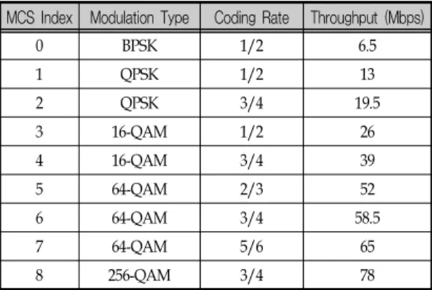
As shown in Table I, IEEE 802.11ac supports 9 different modulation coding schemes (MCS) for 20MHz bandwidth, and each of the MCS indicates a combination of modulation type, coding rate, and maximum throughput.
The format of IEEE 802.11ac in PHY layer is shown in Figure 1. It consists of preamble field and
data field. In the legacy preamble field, Legacy Short Training Field (L-STF) and Legacy Long Training Field (L-LTF) are used to conduct synchronization, channel estimation and compensation as well as power control. Control information such as bandwidth, data rate, beamforming configuration, length of guard interval etc. is contained in Legacy Signal (L-SIG). Apart from the legacy preamble field, IEEE 802.11ac has introduced a new preamble field called Very High Throughput (VHT) preamble field, which contains new control information related to Multi-user Multiple Input Multiple Output (MU-MIMO)[9].
Data field, which carries the data passed down from upper layer, 16-bit service field and padding bits, is at the end of the VHT format.
Ⅳ. SOFTWARE IMPLEMENTATION
4.1 Preamble Field and Data Field EncodingThe preamble field has the legacy preamble and VHT preamble field. Since multi-antenna techniques such as beamforming and MIMO are not used in the implementation of the encoder, VHT-SIG-B field for supporting multi-antenna techniques is not implemented. Apart from VHT-SIG-B field, all other fields are implemented in compliance with IEEE 802.11ac specifications[10].
For the data field, owing to the software flexibility provided by the DSP, the MCS can be determined dynamically by software according to various requirements.
In Figure 2, the whole encoding process is shown under MCS 8, which corresponds to 3/4 coding TABLE 1. MODULATION CODING SCHEME FOR 20MHz
BANDWIDTH
MCS Index Modulation Type Coding Rate Throughput (Mbps)
0 BPSK 1/2 6.5
1 QPSK 1/2 13
2 QPSK 3/4 19.5
3 16-QAM 1/2 26
4 16-QAM 3/4 39
5 64-QAM 2/3 52
6 64-QAM 3/4 58.5
7 64-QAM 5/6 65
8 256-QAM 3/4 78
Fig. 1 Format of Very High Throughput (VHT)
Fig. 2 Encoding Process
rate, 256 QAM modulation, and 78Mbps maximum throughput. The coprocessor FFTC in the C6670 DSP is used to execute 64 point IFFT for both preamble part and data part in the end.
4.2 Utilization of Multi-Cores
One of the challenges of implementing 802.11ac using multicore DSP is how to accurately acquire the synchronization among multicores. If the cores are not synchronized properly, the data transfer would result in errors, and eventually lead to the failure of the whole system.
In this paper, in order to meet the required throughput of IEEE 802.11ac, Core0, Core1, and Core2 are used to encode the data. For synchronizing the cores, instead of using polling method, we used the provided IPC module of the DSP.
In IPC module, there are various functions provided to achieve the communications across cores, such as MessageQ, Notify, etc. However, Notify is more preferable because it is relatively easy to set up, and although the amount of data it allows to transfer at one time is much less than MessageQ, the heavily loaded communication across cores is not needed in this implementation.
The objective of the communication across cores is to send notifications to the other cores indicating that they can start fetching the data from the shard memory and start processing it.
4.3 Optimization
Another challenge of implementing 802.11ac
using multicore DSP is how to optimize the system to the extent where one OFDM symbol can be processed within 4μs. There are certain optimization techniques are applied in this implementation.
Firstly, the optimization level of the compiler is set to the highest level, which is level 3[11]. The compiler can help reduce a massive amount of execution time, however, the downside to that is that the higher optimization level is, the more time it consumes to compile. Sometimes, if the size of the project is considerably large, it may slow down the process of the implementation. Nevertheless, the significant optimization level that the compiler provides can not be neglected.
Secondly, because the scrambling and interleaving processing in IEEE 802.11ac encoder takes up the majority of the total processing time;therefore, instead of calculating the scrambling sequence and interleaving index for each frame in real time, it is better to calculate them beforehand and put them into a lookup table in terms of reducing computing power and execution time The advantage of using lookup table is evident;
however, a lookup table might take up considerably large memory especially when the bandwidth is increased to accommodate more users. In that case, it can be stored in the external memory on the board, but the speed of data fetching would be twice slower than it is stored in the shared memory. To speed up the data fetching from external memory, we can use Enhanced Direct Data Access 3 (EDMA3)[12] to let the EDMA controller to handle the data transfer without the cores consuming cycles to do it.
Thirdly, since the IFFT is FPGA hardware
specifically made in the TMS320C6670 DSP for speeding up IFFT, we managed to initialized two instances of IFFT out of four to help reduce the execution time spent on IFFT, and each instance is run by one core. Although all the four instances of FFTC could be used together to further maximize the level of optimization on IFFT, it is unnecessary to do so because the setup and management of the instances require a fair amount of resources of the DSP such as descriptors, interrupts, memory, etc. In this implementation, using two instances has successfully helped us achieve the desired throughput with acceptable cost.
4.4 DSP Implementation Diagram
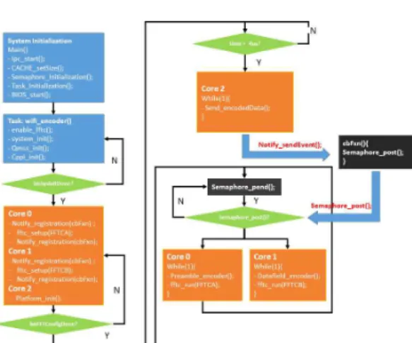
The implementation details of IEEE 802.11ac encoder using multicore DSP are shown in Figure 3. From the figure, we can see that in the initial stage of the system, Core0, Core1, and Core2 are being polled continuously until the system initialization, and FFTC setup are complete. Once the polling is finished, the system moves on to the
next stage, which is iterative. In this stage, Core2 sends the encoded data to the destination every 4μs.
When Core2 is finished the data transfer to the other device, it executes Notify_sendEvent() to send notifications to both Core0 and Core1. After getting notified, the callback function is triggered to execute Semaphore_post() to help Core0 and Core1 escape from the state of being hung on the semaphore.
After that, Core 0 starts processing preamble filed of the frame while Core 1 starts processing data filed of the frame. When the processing of one frame is complete, Core0 and Core1 go back to the state of being hung up on semaphore waiting for the callback function to be triggered again in the next iteration.
Ⅴ. IMPLEMENTATION RESULT AND ANALYSIS
The parameters of the encoder is shown in Table 2. The validation of the output of the implemented system has been confirmed by comparing the output of the implemented encoder with the IEEE 802.11ac encoded signal provided by MATLAB Fig. 3 DSP Implementation diagram of IEEE 802.11ac encoder
TABLE 2. SYSTEM PARAMETERS
Parameter Value
Center Frequency (GHz) 5.0
Bandwidth (MHz) 20
Number of OFDM Symbol 37
MCS 8
IFFT Point 64
Guard Interval (μs) 0.8
Symbol Period (μs) 4
WLAN toolbox[13].
As shown in Table 3, the total encoding time of IEEE 802.11ac is 135μs for 37 OFDM symbols, and 3.65μs for each OFDM symbol, which is less than the required processing time, i.e., 4μs. The throughput of the encoder reaches 78Mbps, which is the maximum throughput for MCS 8.
Compared to other functional blocks, the channel encoding, i.e., BCC (Binary Convolutional Codes) encoding, consumes the most processing time . For the encoding of the BCC, the current output bit should be relevant to the previous output bits by having them convoluted. Because of that, unlike the other parts of encoding process, such as scrambling, interleaving, mapping, etc. where the input data is divided into groups, and each group is processed by different core at the same time, the parallelization of the BCC encoder cannot be implemented. Therefore, with only one core performing the channel encoding, it is inevitable to consume more time for the BCC encoding in comparison with other functional blocks where more computational resources have been used.
As mentioned in section 4, we used notification
function with semaphore mechanism to achieve the synchronization among three cores. However, this method works properly only under the condition when the processing time for Core0 and Core1 is less than that of Core2. If Core2 finishes the data transfer before Core0 and Core1 reach to the next pending on semaphore, the notification sent from Core2 to Core0 and Core1 will be missed.
Consequently, one frame will be lost. Hence, it is vitally important that the task run in Core0 and Core1 should be well optimized so that they can process the frame faster than that of Core2.
In the run time, Core0, Core1, and Core2 are in charge of preamble field, data field, and communicating with another device, respectively.
Therefore, threes cores are completely separated in the proposed system in terms of functionality. Since the preamble field and data field are processed separately in Core0 and Core1, it is much easy to change the radio parameters in the preamble field under this system architecture to adjust to the new requirement without affecting the programs run in Core1 and Core2. Likewise, Core2 only works on the data transfer from the DSP to another device without interfering the execution of Core0 and Core1.
Ⅵ. CONCLUSION
In this paper, we discussed the software implementation details of the IEEE 802.11ac encoder using the TMS320C6670 DSP. The implemented encoder can generate all the signals consisting of preamble field and data field under different MCS TABLE 3. PROCESSING TIME OF THE ENCODER FOR 37
Processing Time Value (μs)
Preamble Field 4
Scrambling 5
BCC Encoder 43
BCC Interleaving 31
Modulation 20
Pilot Insertion 12
FFTC 20
Total 135
in IEEE 802.11ac standard. By utilizing the computational power of multi-core and coprocessors in the DSP, the maximum throughput is obtained with each symbol processed within 4 μs. The software implementation using DSPs provides significant flexibility of the parameter change even after the communication system has been implemented. The implementation of IEEE 802.11ac decoder as well as the implementation of multi-antenna technology are our future work.
Acknowledgement
This research was supported by the Commercialization Promotion Agency for R&D Outcomes (COMPA) funded by the Ministry of Science and ICT (MSIT). [2019K000060]
REFERENCES
[1] R. Akeela and B. Dezfouli, “Software-defined Radios: Architecture, state-of-the-art, and challenges,” Comput, Commun., vol. 128, 2018, pp.106-125.
[2] M. S. Gast, “802.11ac A Survival Guide”, O'Reilly Media, Inc., United States, 2013.
[3] Texas Instruments, "TMS320C6670 Multicore Fixed and Floating-point System-On-Chip Data Manual", SPRS689D, March 2012.
[4] C. R. Berger, V. Arbatov, Y. Voronenko, F.
Franchetti, and M. Püschel, “Real-time software implementation of an IEEE 802.11a baseband receiver on Intel multicore,” ICASSP, IEEE Int.
Conf. Acoust. Speech Signal Process. - Proc., 2011, pp.1693–1696.
[5] A. T. Tran, D. N. Truong, and B. M. Baas, “A complete real-time 802.11a baseband receiver implemented on an array of programmable processors,” Conf. Rec. - Asilomar Conf. Signals, Syst. Comput., 2008, pp.165–170.
[6] Y. Choi, T. W. Kim, J. T. Park, S. W. Kim, and K. H. Tchah, “Design of a baseband modem for IEEE 802.11G wireless lan systems,” Proc. IEEE Int. Symp. Consum. Electron. ISCE, 2003, pp.
140–141.
[7] Texas Instruments, “KeyStone Architecture Fast Fourier Transform Coprocessor (FFTC) User’s Guide”, SPRUGS2C, December 2011.
[8] Texas Instruments, “SYS/BIOS Inter-Processor Communication (IPC) 1.25 User’s Guide”, SPRUGO6E, September 2012.
[9] E. Perahia and R. Stacey, “Next Generation Wireless LANs”, Cambridge University Press, United Kingdom, 2013, pp.62-69.
[10] IEEE Computer Society, “IEEE Standard 802.11s-2011, Specific requirements Part 11 : Wireless LAN Medium Access Control ( MAC ) and Physical Layer ( PHY ) specifications Amendment 10 : Mesh Networking IEEE Computer Society,” IEEE Stand., vol. 2016, 2016.
[11] Texas Instruments, “TMS320C6000 Optimizing Compiler v8.2.x User’s Guide”, SPRUI04B, 2017.
[12] Texas Instruments, "KeyStone Architecture Enhanced Direct Memory Access (EDMA3) Users Guide", SPRUGS5B, May 2015.
[13] MathWorks, "WLAN Toolbox User’s Guide (R2019)", Natick, Massachusetts, United States, September 2019.
▪저자소개▪
장 중 봉 Zhang, Zhong Feng
2018년 3월~현재
한양대학교 전자컴퓨터통신공학과 석사과정
2018년 2월 연변대학교 정보통신공학과 (공학학사)
관심분야 : DSP, vehicular comm, LTE-A, etc
E-mail : zhongfeng.zhang@dsplab.
hanyang.ac.kr
안 흥 섭 Ahn, Heung Seop
2016년 3월~현재
한양대학교 전자컴퓨터통신공학과 박사과정
2016년 2월 한양대학교 전자컴퓨터통신공학과 (공학석사)
2013년 2월 한양대학교 융합전자공학부 (공학학사)
관심분야 : vehicular comm, 5G, LTE, Cell planning, SDR etc.
E-mail : [email protected]
최 승 원 Choi, Seung Won
2012년 3월~현재
HY-MC 연구센터 센터장 2002년~2011년
HY-SDR 연구센터 센터장 1992년~현재
한양대학교 융합전자공학부 교수 1990년~1992년
일본 우정성 통신연구소 선임 연구원
1989년~1990년
ETRI 선임 연구원 1988년~1989년
미국 Syracuse대학 전지 및 전산과 교수
1988년 12월 미국 Syracuse대학 전기공학 (공학박사)
1985년 12월 미국 Syracuse대학 전기공학 (공학석사)
1982년 2월 서울대학교 전자공학 (공학석사) 1982년 2월 한양대학교 전자공학 (공학학사)
관심분야 : SDR, 이동통신, 신호처리 E-mail : [email protected]
논문접수일 : 수 정 일 : 게재확정일 :
2019년 11월 13일 2019년 12월 9일 2019년 12월 17일