545
디지털위성중계기용 SHF대역 입력필터 조립체의 설계 및 구현에 대한 연구
김기중*
A Study on the Design and Implementation of SHF band IFA for Digital Satellite Communication
Ki-Jung Kim
*요 약
본 연구는 디지털위성중계기용 SHF 대역 IFA(: Input Filter Assembly)의 설계 및 구현에 대해 기술하였 다. SHF 대역 입력필터조립체는 Coupler + LPF(: Low Pass Filter) 및 입력필터로 구성된다. 제작 전 우주환 경에 대한 사전 시뮬레이션 분석을 통하여 장비 오동작 가능성을 최소하였으며, 발사환경 시 발생하는 진동에 대한 시뮬레이션을 통해 신뢰성 있는 IFA를 설계하였으며, 제작 후 주요 성능지표에 대해 만족여부 확인 및 사전 성능 시뮬레이션 결과와 비교하였다.
ABSTRACT
This study describes the design and implementation of IFA(Input Filter Assembly) for Digital Satellite Communication. The IFA unit for SHF band consists of coupler, LPF(Low Pass Filter) and input Filter. Through the pre-simulation analysis of space environment, the possibility of the malfunction of equipment minimized and we designed a reliable IFA through simulation for vibration analysis generated during the launch, and compared pre-simulation of main performance results to test results about main performances of IFA after production.
키워드
Digital Satellite Communication, IFA, Space Environment 디지털 위성 중계기, 입력 필터 조립체, 우주 환경
* 교신저자 : 한화시스템 HW팀(레이다) ㆍ접 수 일 : 2017. 06. 20
ㆍ수정완료일 : 2017. 07. 13 ㆍ게재확정일 : 2017. 08. 01
ㆍReceived : Jun 20, 2017, Revised : July 13, 2017, Accepted : Aug 01, 2017 ㆍCorresponding Author : Ki-Jung Kim
HW Team(Radar) Hanwha System Email : [email protected]
Ⅰ. 서 론
기존 아날로그 위성 중계기에서 점차 위성중계기에 대해서도 디지털화가 가속화되고 있다. 아날로그 위성 중계기는 강우에 대한 신호의 감쇄 등의 단점을 가지 고 있다. 아날로그 위성중계기에 비해 디지털위성중계 기는 자동 및 수동 이득 조정 기능 보유, 부채널 스위 칭기능, 방송기능 등을 가지고 있어서 위성 통신 효율
을 극대화할 수 있는 장점을 가지고 있다. 디지털위성 중계기의 개념도는 그림 1과 같다. 안테나로부터 미약 한 신호의 SHF 대역의 신호를 수신하여 입력필터 (IFA : Input Filter Assembly)로 필터링되고, 미약한 신호를 저잡음증폭장치(LNA : Low Noise Amplifier) 로 증폭을 시켜준다. 그리고 입력다중화기(IMUX : Input Multiplexer)가 각 주파수 대역을 필터링하고 하향주파수변환기(Down Converter)를 통해 L대역으 Regular paper Journal of the KIECS. pp. 545-548, vol. 12, no. 4, Aug. 31 2017, t. 84, pISSN 1975-8170 | eISSN 2288-2189
http://dx.doi.org/10.13067/JKIECS.2017.12.4.545
JKIECS, vol. 12, no. 04, 545-548, 2017
546
로 하향 변환한다. 그 신호는 디지털채널증폭부 (Digital Channel Amplifier)를 사용하여 디지털신호처 리를 하고, 다시 L대역을 상향주파수변환기(Up Converter)를 거쳐 SHF대역으로 변환한다. 상향 변환 된 신호를 다시 TWTA(: Traveling Wave Tube Amplifier)를 통해 고출력증폭을 하며, 채널별로 필터 링을 하기 위하여 출력다중화기(OMUX : Output Multiplexer)를 거쳐서 안테나(ANT : Antenna)로 송 출하게 된다[1-2].
그림 1. 디지털위성중계기 개요
Fig. 1 Overview of the digital satellite communication
본 논문에는 지상국으로 수신한 SHF대역의 신호 를 원하는 주파수 대역으로 필터링역할을 하는 입력 필터조립체의 설계, 구현 및 우주환경 분석결과에 대 해 기술한다.
Ⅱ. 본 론
2.1 위성중계기용 입력필터조립체 개요
위성중계기용 입력필터조립체는 지상 단말에서 수 신하는 SHF대역의 신호를 원하는 주파수 대역으로 필터링하는 역할을 한다. 본 위성중계기용 입력필터조 립체의 군지연특성은 10nsp-p 이하, 대역외 억압특성 은 75dBc 이상을 만족하도록 설계 및 구현하였다. 또 한 우주환경분석(진동)을 통하여 우주환경에 운용에 문제없음을 사전 검증하였다.
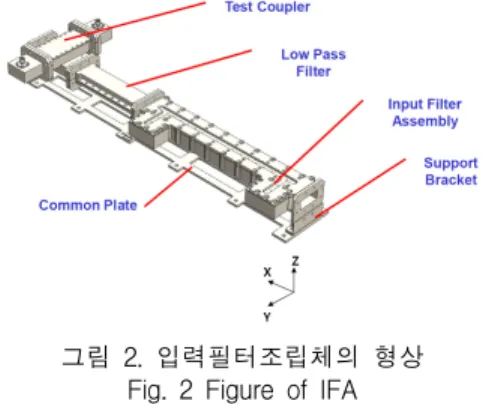
입력필터조립체는 그림 2와 같이 Coupler, LPF, 입 력필터 등으로 구성된다. LPF는 고주파대역외의 신호 를 필터링하는데 사용되며, 입력필터는 운용주파수 대 역인 500MHz 대역을 필터링한다[3-4].
그림 2. 입력필터조립체의 형상 Fig. 2 Figure of IFA
입력필터조립체는 그림 3과 같이 입력단에 Test Coupler, 운용대역 이상의 신호를 필터링해주는 LPF, 운용대역만을 필터링해주는 입력필터로 구성되어 있다.
그림 3. 입력필터조립체의 블록도 Fig. 3 Internal block of IFA
2.2 위성중계기용 입력필터조립체의 설계 및 측 정 결과
위성중계기용 입력필터조립체의 전 부품에 대해서 정지궤도급에서 사용가능한 부품으로 적용하였다.
IFA의 입력단에는 우주환경 시험시 인가되는 신호를 모니터링 할 수 있도록 입력신호 대비 –30dB 감쇄되 는 Test Coupler로 구성되어 있다.
그림 4. 입력필터조립체의 Test Coupler 형상 및 특성
Fig. 4 Figure and characteristic of test coupler of IFA
디지털위성중계기용 SHF대역 입력필터조립체의 설계 및 구현에 대한 연구
547
IFA의 내부의 LPF는 그림 5와 같이 알루미늄재질의 도파관 L,C등가역할을 하는 공진기로 구성이 되었다.
그림 5. 입력필터조립체의 LPF 내부구조 Fig. 5 Internal configuration of IFA
LPF 다음에는 원하는 주파수 대역만 필터링하는 입력필터로 구성되어 있다. 그림 6은 입력필터의 구조 와 등가 시뮬레이션 회로를 보여준다.
그림 6. 입력필터조립체의 입력필터 내부구조 Fig. 6 Internal configuration of input filter of IFA
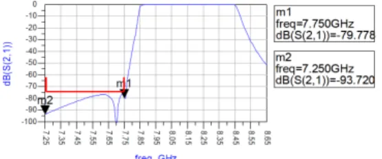
그림 7은 입력필터조립체의 입력필터 특성을 보여 준다. 상향링크대역에 대해서는 –79dBc이상으로 시스 템 요구사항인 75dBc를 만족한다. 억압특성이 충분히 확보가 안되면 고출력증폭된 신호가 수신단에 인가되 어 발진 등의 악영향이 일어날 수 있다[5-6].
그림 7. 입력필터조립체의 LPF 삽입손실 특성 Fig. 7 Insertion loss of LPF of IFA
그림 8은 입력필터조립체의 군지연특성을 보여준다.
최대 운용대역에서 7.3nsp-p이하로 목표규격인 10nsp-p를 만족한다.
그림 8. 입력필터조립체의 군지연특성 Fig. 8 Group delay of IFA
2.3 디지털채널증폭부용 입력필터조립체의 우주 환경 시뮬레이션 분석
우주환경은 태양에 의한 방사능이 존재하는 환경과 태양표면의 흑점 등의 분출로 인한 전자회로에 임펄 스 잡음 등의 발생 및 공기가 존재하지 않아 공기에 의한 열대류가 존재하지 않는 혹독한 환경이다[7-8].
발사환경 및 우주환경에 대한 생존성을 사전 검증 하기 위하여 본 논문에서는 진동에 대한 시뮬레이션 을 진행하였다. 입력필터조립체는 전자부품이 실장되 지 않는 구성품이기 때문에 방사능분석은 해당사항이 없고, 진동분석에 대해서만 수행하였다. 발사환경의 입력필터조립체에 대한 진동분석은 그림 9와 같다.
그림 9. 입력필터조립체의 진동분석 Fig. 9 Vibration analysis of IFA
진동공진주파수가 X축은 293.5Hz, Y축은 335.6Hz,
Z축은 463.8Hz로 시스템 요구사항인 150Hz이상으로
진동조건을 만족한다.
JKIECS, vol. 12, no. 04, 545-548, 2017
548
Ⅲ. 결 론
본 논문은 위성중계기용 입력필터조립체(IFA)의 설 계 및 구현에 대해 기술하였다.
제작 전 입력필터조립체의 삽입손실 및 대역외 억 압특성, 군지연특성 등에 대해서 사전 분석을 하였으 며, 제작 후 주요 성능지표에 대해서 시험을 통하여 요구사항 만족여부 및 시뮬레이션 분석결과와 비교하 였다. 본 연구 과정 및 결과를 바탕으로 고신뢰성이 요구되는 정지궤도 및 저궤도 위성용 입력필터조립체 개발에 활용할 예정이다.
References
[1] K. Kim and H. Seo, “The system performance analysis and implementation of Digital Communication Satellite,” J. of the Korea Institute of Electronic Communication Sciences, vol. 4, no. 9, 2014, pp. 439-445.
[2] K. Kim and H. Ko, “The Optimization using PCB EM interpretation of GEO satellite's L Band Converter,” J. of the Korea Institute of Electronic Communication Sciences, vol. 8, no. 8, 2013, pp.
1219-1226.
[3] K. Kim, “The Study on the Design and Implementation of SHF band Upconverter of Digital Satellite Communication,” J. of the Korea Institute of Electronic Communication Sciences, vol. 12, no. 2, 2017, pp. 261-266.
[4] S. Kim and Y. Rhee, “Implementation of Ku-band Low Noise Block for Global Multi-Band Digital Satellite Broadcasting,“ J. of the Korea Institute of Electronic Communication Sciences, vol. 11, no. 1, 2016, pp. 23-28.
[5] M. Go, H. Shin, and H. Park, “A RF Module for digital terrestrial and multi-standard reception,” J.
of the Korea Institute of Electronic Communication Sciences, vol. 1, no. 1, 2006, pp. 16-27.
[6] K. Kim and B. Kim, “The Study on the design and implementation of a X-band 25W Power Amplifier
Module using GaAs MMIC,” J. of the Korea Institute of Electronic Communication Sciences, vol. 9, no. 11, 2014, pp. 1311-1316.
[7] ESA Requirements and Standards Division, “Space Engineering: Testing,” European Space Agency ECSS-E-10-03A, Feb. 2002.
[8] T. Kim, J. Park, and Y. Rhee, “Implementation of Ka-band Low Noise Block Converter For Satellite,“
J. of the Korea Institute of Electronic Communication Sciences, vol. 3, no. 2, 2008, pp. 93-100.
저자 소개
김기중(Ki-Jung Kim)