자동차용 알루미늄/복합재료 하이브리드 동력전달축의 압입접합부 설계에 관한 연구
김학성 † · 이대길 *
A study on the design of the press fit joint for automotive aluminum/composite hybrid propeller shaft
Hak Sung Kim, Dai Gil Lee
Key Words : Automotive propeller shaft (자동차용 동력전달축), Press fit joint (압입접합부), small teeth (미세 요철)
Abstract
Press fitting method for joining of a hybrid tube and steel ring with small teeth for automotive aluminum/composite hybrid propeller shaft was devised to improve reliability and to reduce manufacturing cost, compared to other joining methods such as an adhesively bonded joint, bolted joint or welded joint. To obtain high strength of the press fit joint, an optimal design method for the teeth was devised with respect to number and shape of the steel teeth. Torsional static, fatigue tests and finite element analysis of the press fit joint were performed with respect to experimental variables. The developed optimal design method predicted well the static torque capability and failure mode of the press fit joint. Also, it provided design guide line of press fit joint for improving torsional static and fatigue characteristics.
기호설명 T : 압입접합부에 가해지는 토크 N : 강철 요철 개수
l: 압입접합부의 접합 길이 ws: 강철 요철의 너비 wal: 알루미늄 요철의 너비 h: 강철, 알루미늄 요철의 높이
Tsteel, tensile : 강철요철의 인장 파괴모드 토크
Tsteel, compressive: 강철요철의 압축 파괴모드 토크
Tal, tensile: 알루미늄 요철의 인장 파괴모드 토크
Tal, compressive: 알루미늄 요철의 압축 파괴모드 토크
1. 서 론
1.1 자동차용 알루미늄/복합재료 동력전달축 동력전달축은 트랜스미션 (Transmission)과 차동 기어박스 (Differential gear box) 사이의 길이 1.5 m 정도의 고속 회전하는 중공축으로 정의된다.
A lum inum tube
C om posite layer Joint betw een yoke and hybrid tube
U niversal joint Bracket Inner spline
(a)
(b)
Fig. 1 Schematic diagrams of propeller shafts: (a) Two piece steel propeller shaft; (b) One piece aluminum/composite propeller shaft (International patent pending).
† 한국과학기술원 기계공학과
E-mail : [email protected]
TEL : (042)869-3261 FAX : (042)869-5221 * 한국과학기술원 기계공학과 정교수
복합재료를 자동차용 동력전달축 제작에 사용할 경우 비강성이 강철 재료에 비하여 우수하기 때 문에 기존의 강철로 이루어진 2-piece 동력전달 축 구조를 일체형으로 제작할 수 있다 (1). 따라 서 구조가 단순해 지고, 고속 회전시 센터지지 베어링에서 발생하는 진동 및 소음이 줄어든다.
또한 무게가 50 % 정도 감소하여 연비를 크게 향상 시킬 수 있다. 그러나 복합재료의 가격이 아직까지 상대적으로 높으므로 이를 극복하기 위하여 알루미늄/복합재료로 이루어진 하이브리 드 구조로 개발되고 있다. 이때 알루미늄 튜브 는 토크를 견디는 역할을 수행하고 복합재료는 고유진동수를 높여 훨링 (Whirling)을 방지하는 역할을 한다 (1). 한편 동력전달축은 차체와의 연 결을 위하여 금속 요크와의 접합부를 필수적으 로 가진다. 이런 접합부를 제조하기 위한 기존 의 접합 방법에는 크게 접착제를 이용한 접합, 볼트를 이용한 접합, 용접을 이용한 접합이 있 다. 그러나 접착 접합은 주위의 온도, 습도에 대 하여 접합 강도가 급격히 감소하는 단점이 있고 볼트 혹은 리벳을 이용한 접합은 접합에 필요한 구멍을 가공해야 하며 구멍 주위가 피로 파괴에 취약해지며 불균일한 볼트의 질량에 의해 동력 전달축의 고속 회전시 밸런싱이 어려워지는 단 점이 있다. 또한 용접을 이용한 접합은 알루미 늄의 높은 열 전도도와 표면의 산화막으로 인하 여 균일한 용접이 어렵고 용접열에 의하여 복합 재료의 물성이 저하되는 단점이 있다. 이와 같 은 접합부의 취약성으로 인하여 하이브리드 튜 브와 금속 요크의 접합은 매우 까다로운 것으로 알려져 왔다.
1.2 요철로 맞물리는 압입접합부 개발
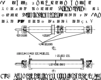
본 연구에서는 기존 접합방법의 단점을 극복하 고 신뢰성 있는 접합을 위하여 내면에 작은 요 철들이 구비된 강철링을 이용한 하이브리드 샤 프트와 알루미늄 요크의 압입 접합 방법을 개발 하였다. (국내 및 국제 특허 출원) 개발된 방법 에서는 Fig. 2 와 같이 내면에 작은 요철들이 가 공되어 있는 강철링의 양단을 하이브리드 샤프 트, 알루미늄 요크에 각각 압입 접합한다. 이로 서 하이브리드 샤프트, 알루미늄 요크 외면에 강철 요철이 파고들어 알루미늄 요철을 자동 생 성하고 강철링 내면의 요철과 기계적 맞물림을 이루어 높은 정적, 동적 토크 용량을 얻을 수 있게 된다. 또한 내면에 요철이 구비된 강철링 은 브로칭 (Broaching)등을 통하여 대량으로 값 싸게 제작할 수 있으므로 생산 단가를 줄일 수
Press fit Press fit
Aluminum yoke Teeth
Steel ring Hybrid tube Aluminum tube
Composite layer
Steel teeth Aluminum grooves produced
(a) (b)
Fig. 2 Press fit joint between the aluminum/composite hybrid tube and the aluminum yoke using A steel ring which has many teeth in the axial direction on its inner surface: (a) before assembly; (b) after assembly (International patent pending).
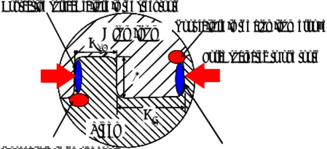
F
wstAluminum
Steel
Force subjected to one tooth F
Root failure in the steel tooth Contacting surface failure in the aluminum groove Contacting surface failure in the steel tooth
Root failure in the aluminum groove
walAluminum
Steel ws
h F
wstAluminum
Steel
Force subjected to one tooth F
Root failure in the steel tooth Contacting surface failure in the aluminum groove Contacting surface failure in the steel tooth
Root failure in the aluminum groove
walAluminum
Steel ws h
Fig. 3 Failure modes in the teeth of the press fit joint.
있으며 단순한 압입 공정 만으로 공정이 완성되 므로 생산 공정을 단순화 할 수 있다. 본 연구에 서는 압입 접합부의 신뢰성 있는 설계를 위하여 단순 계산식을 이용한 최적 설계 방법을 개발하 였으며 정, 동적 토크 실험과 유한요소해석을 통 하여 이를 검증하였다. 이를 통하여 하이브리드 동력전달축용 압입접합부의 설계 방법을 제공하 였다.
2. 압입접합부의 최적설계
2.1 압입접합부의 파괴 모드 맵 구성
Fig. 3 에 압입 공정 후 자동 생성된 알루미늄 요 철과 강철 요철이 맞물려 있는 개략도를 나타내 었다. 본 연구에서는 시편 제작의 편의를 위하여 모따기된 사각 형상을 요철 형상으로 정하였다.
이때 강철 요철의 형상은 요철의 높이 (h)와 너 비 (ws)로 정의된다. 압입 접합부에 토크가 가해 졌을 때 맞물린 강철 요철과 알루미늄 요철에는 Fig. 3 과 같이 알루미늄 요철의 인장 파괴, 압축 파괴와 강철 요철의 인장 파괴, 압축 파괴의 네 가지 파괴 모드가 존재한다. 각 파괴 모드별 토 크 용량을 계산하기 위하여 계산을 수행하였다.
압입접합부에 토크 (T)가 가해졌을 때 각 요철에 작용하는 힘 (F)은 다음과 같이 계산된다.
Nr
F= T (1) 각 요철은 분포하중 F/h 를 받는 단순보로 가정 할 수 있다. 이때 강철 요철의 이뿌리 (root)에 발 생하는 인장 응력 σsteel은 다음과 같이 계산된다.
2 2
3 3
s s
steel
lNrw Th lwFh =
σ = (2) 강철 요철의 이뿌리에 발생하는 전단 응력τsteel이 일정하다고 가정하면 다음과 같이 계산된다.
s s
steel
lNrw T lwF =
τ = (3) 강철, 알루미늄 요철의 접촉면에 발생하는 압축
응력 σcompressive은 다음과 같다.
hlNr T hl
F
e
compressiv = =
σ (4) 강철 요철 사이의 알루미늄 요철의 너비 wal 는 다음과 같이 계산된다.
N w N wal =2πr− ⋅ s
(5) 알루미늄 요철의 이뿌리에서 발생하는 인장 응력 σ 과 전단응력al τ 은 각각 다음과 같이 계산된다. al
2
2 2
3
3
⋅
= −
=
al s
al r N w
N lNr
Th lw
Fh
σ π (6)
⋅
= −
=
=
s al
al
al r N w
N lNr
T lNrw
T lw
F τ π
2 (7)
강철 요철, 알루미늄 요철의 이뿌리의 등가 본- 미세스 (Von-mises) 응력σequiv은 다음과 같이 계 산된다.
2
2 3τ
σ
σequiv = + (8)
위에서 계산된 응력에 강철, 알루미늄의 인장, 압 축 강도를 대입시키면 각 파괴 모드에서의 토크 용량을 다음과 같이 유도할 수 있다.
) 3
(
3 2 2
2 ,
s s t steel tensile
steel
w h
Nrlw T X
= + (9) Nrhl
X
Tsteel,compressive= steelc (10)
) ) 2
( 3
( 3
) 2
(
2 2
2
2 ,
a
s s t
al tensile
l h N r Nw
Nw r rl T X
− +
= −
π
π (11)
Nrhl X
Tal,compressive= alc (12) Fig. 4 에 본 연구에서 사용된 시편과 그 치수를 표시하였고 Table 1 에 실험에 사용된 강철링과
teeth
Axial Guide for press fit operation Ø 8.5
Ø 50 Ø 50.5 Ø 90 Ø 70 Ø 56
8 5 teeth
Axial Guide for press fit operation Ø 8.5
Ø 50 Ø 50.5 Ø 90 Ø 70 Ø 56
8 5
Fig. 4 Configuration of the steel ring specimen which has the rectangular shape teeth in the axial direction on the inner surface (unit: mm).
Root failure of the aluminum grooves Contacting surface failure of the steel teeth Contacting surface failure of the aluminum grooves
(a) (b)
(d) Root failure of the steel teeth
w2h05
0 300 600 900 1200 1500
0 10 20 30 40 50 60 70 80
Number of protrusions
Static torque capacity (Nm)
Optimal point
900 600 300 0 1500 1200
0 10 20 30 40 50 60 70 80
w1h05
0 300 600 900 1200 1500
0 20 40 60 80 100 120
Number of protrusions
Static torque capacity (Nm)
Optimal point
900 600 300 0 1500 1200
0 20 40 60 80 100 120
Number of steel teeth Number of steel teeth
0 300 600 900 1200 1500
0 20 40 60 80 100 120 140 160 180
Number of protrusions
Static torque capacity
(c)
Optimal point
900 600 300 0 1500 1200
0 20 40 60 80 100 120 140 160 180 Number of steel teeth
0 300 600 900 1200 1500
0 50 100 150 200 250 300
Number of protrusions
Static torque capacity
Optimal point
900 600 300 0 1500 1200
0 50 100 150 200 250 300 Number of steel teeth
Fig. 5 Failure mode maps when the height of the steel teeth is 0.5 mm with respect to the steel tooth width: (a) 2.0 mm; (b) 1.0 mm; (c) 0.5 mm; (d) 0.2 mm.
Table 1 Mechanical property of the materials Tensile
strength (Xt)
Compressive strength (Xc) Aluminum
(6061-T6)
270 MPa 300 MPa Steel
(SM45C)
370 MPa 400 MPa
알루미늄 튜브의 물성을 나타내었다. 유도된 각 파괴 모드별 토크 용량으로부터 Fig. 5 와 같이 요철 너비, 높이에 대한 파괴 모드 맵을 구성하 였다. 유도된 네가지 토크값 중 가장 낮은 토크 가 압입 접합부의 토크 용량이며 이로부터 강철 요철의 형상 (너비, 높이)별로 최대 토크 용량을 갖는 최적의 요철 개수를 얻을 수 있다.
2.2 압입 접합부의 최적 설계
압입 접합부의 길이 (l)와 반지름 (r)이 정해지면 압입접합부 최적설계의 설계 변수 벡터 X 는
1359
1359
1359 1274
1189
1018 848 678
507 1274
1189 1104
1018 933 848 763 678 593 507 422 337 252
1104 933 763
width (mm)
Height(mm)
0.25 0.5 0.75 1
0.2 0.4 0.6 0.8 1
Optimal aspect ratio (height/width) = 0.7 ~ 1
Width (mm) 1359
1359
1359 1274
1189
1018 848 678
507 1274
1189 1104
1018 933 848 763 678 593 507 422 337 252
1104 933 763
width (mm)
Height(mm)
0.25 0.5 0.75 1
0.2 0.4 0.6 0.8 1
Optimal aspect ratio (height/width) = 0.7 ~ 1
Width (mm)
Fig. 6 Maximum torque capability (Nm) at the optimal tooth number of the steel ring with respect to the width and height of the steel teeth.
Press fit joint Adhesively bonded joint Press fit joint Adhesively bonded joint
Fig. 7 Press fit joint specimen between the aluminum tube and the toothed steel ring.
0 300 600 900 1200 1500
0 20 40 60 80 100 120 140 160 180
Number of protrusions
Static torque capacity (Nm)
Root failure of the aluminum grooves Root failure of the steel teeth Contacting surface failure of the steel teeth Contacting surface failure of the aluminum grooves Experimental results
w1h05
0 300 600 900 1200 1500
0 20 40 60 80 100 120
Number of protrusions
Static torque capacity (Nm)
0 20 40 60 80 100 120 1500
1200 900 600 300 0
Static torque capability (Nm)
(b) (a)
(c)
1500 1200 900 600 300
0
0 20 40 60 80 100 120 140 160 180 Static torque capability (Nm)
w2h05
0 300 600 900 1200 1500
0 10 20 30 40 50 60 70 80
Number of protrusions
Static torque capacity (Nm)
900 600 300 0
Static torque capability (Nm) 1500
1200
0 10 20 30 40 50 60 70 80
0 300 600 900 1200 1500
0 20 40 60 80 100 120 140 160 180
Number of protrusions
Static torque capacity (Nm)
Root failure of the aluminum grooves Root failure of the steel teeth Contacting surface failure of the steel teeth Contacting surface failure of the aluminum grooves Experimental results
w1h05
0 300 600 900 1200 1500
0 20 40 60 80 100 120
Number of protrusions
Static torque capacity (Nm)
0 20 40 60 80 100 120 1500
1200 900 600 300 0
Static torque capability (Nm)
(b) (a)
(c)
1500 1200 900 600 300
0
0 20 40 60 80 100 120 140 160 180 Static torque capability (Nm)
w2h05
0 300 600 900 1200 1500
0 10 20 30 40 50 60 70 80
Number of protrusions
Static torque capacity (Nm)
900 600 300 0
Static torque capability (Nm) 1500
1200
0 10 20 30 40 50 60 70 80
Fig. 8 Experimental results and failure mode maps of the press fit joint when the steel tooth height was 0.5 mm with respect to the steel tooth width: (a) 2.0 mm; (b) 1.0 mm; (c) 0.5 mm.
다음과 같이 정의된다.
) , , (N w h
X = s (13) 최적 설계의 목적 함수는 다음과 같이 정의된다.
0 2 0 0 4 0 0 6 0 0 8 0 0 1 0 0 0
0 5 1 0 1 5 2 0
A ngle (d egree)
Torque (Nm)
0 2 0 0 4 0 0 6 0 0 8 0 0 1 0 0 0
0 5 1 0 1 5 2 0
A n gle (d egree)
Torque (Nm)
0 2 0 0 4 0 0 6 0 0 8 0 0 1 0 0 0
0 5 1 0 1 5 2 0
An gle (d egree)
Torque (Nm)
(a)
(b)
(c)
G radual contacting surface failure of the alum inum grooves
C atastrophic root failure of the alum inum grooves
Sim ultaneous contacting surface failure, root failure of the alum inum grooves
0 2 0 0 4 0 0 6 0 0 8 0 0 1 0 0 0
0 5 1 0 1 5 2 0
A ngle (d egree)
Torque (Nm)
0 2 0 0 4 0 0 6 0 0 8 0 0 1 0 0 0
0 5 1 0 1 5 2 0
A n gle (d egree)
Torque (Nm)
0 2 0 0 4 0 0 6 0 0 8 0 0 1 0 0 0
0 5 1 0 1 5 2 0
An gle (d egree)
Torque (Nm)
(a)
(b)
(c)
G radual contacting surface failure of the alum inum grooves
C atastrophic root failure of the alum inum grooves
Sim ultaneous contacting surface failure, root failure of the alum inum grooves
Fig. 9 Torque-twisting angle diagram of press fit joint (when the width and height of steel teeth were 2.0 mm and 0.5 mm, respectively) with respect to the number of the steel teeth: (a) 10; (b) 45 (optimal number); (c) 50.
Find the vector X to maximize the objective function Tmax
Tmax= min(Tsteel,tensile,Tsteel,compressive,Tal,tensile,Tal,compressive) (14) Fig. 5 의 파괴 모드맵을 통하여 요철의 높이, 너 비가 각각 0.5 mm, 2.0 mm 일 때 최적 요철 개수 45 개에서 알루미늄 요철의 압축 파괴와 알루미 늄 요철의 굽힘 파괴가 동시에 발생하며 최대 토 크는 930 Nm 임을 예측할 수 있다. 또한 요철의 높이, 너비가 각각 0.5 mm, 0.2 mm 인 경우엔 최 적 요철 개수 250 개에서 강철 요철의 굽힘 파괴 와 알루미늄 요철의 굽힘 파괴가 동시에 발생하 며 최대 토크가 810 Nm 임을 예측할 수 있다. 이 와 같이 요철의 너비, 높이가 달라지면 그에 따 라 압입 접합부의 파괴 모드, 최대 토크 용량 또 한 달라짐을 알 수 있었다. Fig. 6 에 강철 요철의 세장비 (높이/너비)에 따른 최적 강철 요철개수에 서의 최대 토크 용량을 나타내었다. 압입 접합부 의 토크 용량은 요철의 세장비가 대략 0.7 ~ 1 일 경우 최대 (1,360 Nm)가 됨을 알 수 있다.
3. 압입 접합부의 정적, 동적 토크 시험 3.1 압입 접합부의 정적 토크 시험
작성된 파괴 모드맵을 검증하기 위하여 압입 접 합부의 정적 토크 시험을 수행하였다. Fig. 7 에
시편 모습을 나타내었다. 강철링 내면의 요철은 EDM (Electric discharge machining)을 이용해 요철 의 높이, 너비, 개수를 달리하며 가공하였으며 알 루미늄 튜브 끝단에 접합길이 5 mm 로 압입 접 합 하였다. 알루미늄 튜브 반대쪽 끝단에는 지그 와의 장착을 위하여 접착 길이가 35 mm 인 강철 링을 접착 접합 하였다. 요철의 높이, 너비를 변 화시키고 그에 따라 요철의 개수를 변화시키면서 정적 토크 시험을 수행하였다. Fig. 8 에 실험 결 과와 파괴모드맵을 함께 도시하였다. 파괴 모드 맵이 압입 접합부의 토크용량을 잘 예측함을 알 수 있다. Fig. 9 에 요철의 높이, 너비가 각각 0.5 mm, 2.0 mm 인 경우 요철 개수에 따른 토크-각도 곡선을 나타내었다. 요철의 개수가 최적개수 45 개 보다 적은 경우엔 알루미늄 요철의 점진적인 압축 파괴가 이루어졌고 최적 개수보다 많은 경 우엔 알루미늄 요철의 갑작스런 인장 파괴가 발 생하였다. 요철 개수가 최적개수와 같은 경우에 는 두 파괴 모드가 동시에 발생하였다. 이 밖의 경우도 모두 파괴 모드맵으로부터 예측된 파괴모 드를 보이며 파괴되었다. 따라서 파괴 모드맵은 압입접합부의 정적 토크 용량, 정적 파괴 모드를 잘 예측함을 알 수 있었다. 최적 설계법을 이용 하여 압입접합부를 설계한 결과 요철의 높이, 너 비, 개수가 각각 0.5 mm, 0.5 mm, 120 개일 때 최 대 정적 토크 1,350 Nm 를 얻을 수 있었으며 이 때 압입 접합부의 평균 전단 강도 (τ )는 다음ave 과 같이 계산된다.
l r T
avg 2π 2
τ =
(15) 계산된 압입접합부의 평균 전단강도 75 MPa 는 기 존 접착 접합부의 최대 전단강도 25 MPa 에 비해 약 300 % 향상된 값으로서 최적 설계를 통하여 접합부의 정적 강도를 크게 향상시켰음을 확인하 였다 (2).
3.2 압입 접합부의 동적 토크 시험
압입 접합부의 동적 토크 특성을 알아보기 위하 여 동적 토크 시험을 수행하였다. 실험 속도는 10 Hz 로 하였으며 응력비 (R)는 - 1 로 정하였다.
정적 시험과 마찬가지로 요철의 너비, 높이에 따 라 요철의 개수를 변화 시켜가며 동적 토크 실험 을 수행하였다. Fig. 10 에 요철의 너비, 높이가 각 각 0.5m, 0.5 mm 일 경우 요철 개수에 따른 S-N Curve 를 도시하였다. 압입 접합부의 피로 한도는 파괴 모드맵에서 얻어진 최적 요철 개수에서 가 장 크게 나타남을 확인하였다. 요철의 높이, 너비 가 달라져도 파괴 모드 맵에서 예측된 각 경우의
0 10 20 30 40 50 60 70 80
1.E+00 1.E+01 1.E+02 1.E+03 1.E+04 1.E+05 1.E+06 1.E+07 Fatigue life (cycles)
Alternating shear stress (MPa)
: 120 ea (optimal in static case) : 50 ea (compressive failure region) : 150 ea (tensile failure region)
0.0E+00 2.0E+05 4.0E+05 6.0E+05 8.0E+05 1.0E+06 1.2E+06 1.4E+06
50 120 150
Number of protrusions (w:0.5mm, h:0.5mm)
Fatigue life (cycles)
Number of steel teeth 0
10 20 30 40 50 60 70 80
1.E+00 1.E+01 1.E+02 1.E+03 1.E+04 1.E+05 1.E+06 1.E+07 Fatigue life (cycles)
Alternating shear stress (MPa)
: 120 ea (optimal in static case) : 50 ea (compressive failure region) : 150 ea (tensile failure region)
0.0E+00 2.0E+05 4.0E+05 6.0E+05 8.0E+05 1.0E+06 1.2E+06 1.4E+06
50 120 150
Number of protrusions (w:0.5mm, h:0.5mm)
Fatigue life (cycles)
Number of steel teeth
Fig. 10 Dynamic torque test results when the width and height of the steel teeth were 0.5 mm and 0.5 mm: (a) S-N curve; (b) Fatigue life with respect to number of teeth when the shear stress was 26 MPa
0 10 20 30 40 50 60 70 80
1.E+00 1.E+01 1.E+02 1.E+03 1.E+04 1.E+05 1.E+06 1.E+07 Fatigue life (cycles)
Alternating shear stress (MPa)
: w=0.5 mm, h=0.5 mm, N=120 ea (optimal) : w=1 mm, h=0.5 mm, N=70 ea (optimal)
0.0E +00 2.0E +05 4.0E +05 6.0E +05 8.0E +05 1.0E +06 1.2E +06 1.4E +06
70 120
Fatigue life (cycle
w=1 mm, h=0.5 mm N=120 ea (optimal)
w=0.5 mm, h=0.5 mm N=70 ea (optimal) 0
10 20 30 40 50 60 70 80
1.E+00 1.E+01 1.E+02 1.E+03 1.E+04 1.E+05 1.E+06 1.E+07 Fatigue life (cycles)
Alternating shear stress (MPa)
: w=0.5 mm, h=0.5 mm, N=120 ea (optimal) : w=1 mm, h=0.5 mm, N=70 ea (optimal)
0.0E +00 2.0E +05 4.0E +05 6.0E +05 8.0E +05 1.0E +06 1.2E +06 1.4E +06
70 120
Fatigue life (cycle
w=1 mm, h=0.5 mm N=120 ea (optimal)
w=0.5 mm, h=0.5 mm N=70 ea (optimal)
Fig. 11 Dynamic torque test results with respect to aspect ratio (height/width) at optimal number of steel teeth: (a) S-N curve; (b) Fatigue life with respect to aspect ratio (height/width) at optimal number of steel teeth when the shear stress was 26 MPa
최적 요철 개수에서 최대의 피로 한도를 얻을 수 있음을 확인하였다. Fig. 11 에 요철의 세장비 (높 이/너비)에 대한 최적 요철 개수에서의 피로 수 명을 나타내었다. 요철의 세장비가 1 인 경우 세 장비 0.5 인 경우에 비해 상대적으로 높은 피로 한도를 얻을 수 있었으며 이는 역시 파괴 모드맵 의 경향과 일치하였다.
피로 파괴된 알루미늄 튜브를 관찰하였고 Fig. 12 에 나타내었다. 시편의 피로 파괴는 압입 접합부 끝단에서부터 발생, 진전되었으며 이는 요철 끝 단의 응력 집중에 의한 것으로 판단된다.
Crack initiation at the end of press fit joint in the aluminum tube Crack initiation at the end of press fit joint in the aluminum tube
Fig. 12 Photograph of the fractured press fit joint specimen after torsional fatigue test.
Applied torque
Cyclic symmetric fixed
Steel ring
Aluminum tube Applied torque
Cyclic symmetric fixed
Steel ring
Aluminum tube
Fig. 13 FE model of press fit joint.
0 50 100 150 200 250 300 350
0 1 2 3 4 5
Axial direction (mm)
Mises stress (MPa)
mises_180 mises_90 mises_50
x z
y Plot line
N: 50 N: 120 N: 180 270 MPa
0 50 100 150 200 250 300 350
0 1 2 3 4 5
Axial direction (mm)
Mises stress (MPa)
mises_50 mises_70 mises_110N: 110 N: 70 N: 50
(a)
(b)
0 50 100 150 200 250 300 350
0 1 2 3 4 5
Axial direction (mm)
Mises stress (MPa)
mises_180 mises_90 mises_50
x z
y Plot line
N: 50 N: 120 N: 180 270 MPa
0 50 100 150 200 250 300 350
0 1 2 3 4 5
Axial direction (mm)
Mises stress (MPa)
mises_50 mises_70 mises_110N: 110 N: 70 N: 50
(a)
(b)
Fig. 14 Stress distribution of aluminum grooves along the axial direction of the press fit joint with respect to steel tooth width (mm): (a) 0.5; (b) 1.0.
4. 유한 요소 해석
4.1 유한 요소 모델링
토크를 받는 압입 접합부의 응력 분포와 파괴 거 동을 분석하기 위하여 유한요소 해석을 수행하였 다. 상용 유한요소 해석 프로그램 ABAQUS 6.3 (Hibbits, Karlsson&Sorenson, USA)을 사용하였으며 모델을 Fig. 13 에 나타내었다. 계산 시간을 단축 하기 위하여 반복 대칭 (Cyclic symmetric) 경계조 건을 이용하여 전체 접합부 중 한 부분의 알루미 늄, 강철 요철만을 모델링 하였다. 요철 사이의
맞닿는 면은 접촉면 (Contacting surface)로 지정하 였고 마찰 계수는 0.3 으로 설정하였다. 하중으로 는 500 Nm 의 토크를 가하였으며 실험 결과와의 비교를 위하여 요철의 너비, 높이와 개수를 변화 시켜가며 모델링하고 해석을 수행하였다.
4.2 해석 결과 및 토의
Fig. 14 에 해석 결과를 나타내었다. 요철로 맞물 린 압입접합부에 토크가 가해졌을 때 요철의 끝 단에서 응력 집중이 발생함을 확인할 수 있었으 며 이는 피로 파괴된 시편에서 관찰된 균열 발 생 지점과 일치하였다. Fig. 14 (a)에 요철의 높이, 너비가 각각 0.5 mm, 0.5 mm 일 경우 요철의 개수 에 따른 본 미세스 (Von mises) 응력 분포를 나타 내었다. 요철의 개수가 최적 개수 120 개일 경우 전체적인 응력 크기가 다른 경우에 비해 상대적 으로 작아짐을 확인할 수 있다. 한편 Fig. 14(b)에 서 요철의 높이 너비가 각각 0.5 mm, 1.0 mm 일 경우엔 최적 요철 개수 70 개에서 전체적 응력의 크기가 상대적으로 작아짐을 알 수 있었다. 또한 세장비가 1 일 경우 세장비가 0.5 인 경우에 비 하여 최적 요철 개수에서의 응력 수준이 전체적 으로 낮다는 사실도 알 수 있었다. 유한 요소 해 석 결과 앞에서 작성된 파괴 모드맵이 동적 하중 하의 접합부 응력 경향도 잘 예측할 수 있음을 확인하였으며 실험 결과와도 일치하였다.
5. 결 론
본 연구에서는 하이브리드 동력전달축과 금속 요 크의 압입 접합법을 개발하였고 간단한 수식을 이용한 최적 설계 기법을 제안하였다. 또한 정, 동적 토크 시험과 유한요소해석을 통하여 개발된 최적설계기법의 실제 설계로의 적용성을 확인하 였다.
후 기
본 연구는 NRL 국가 지정 연구실 과제 및 BK21 과제의 도움으로 수행되었음을 밝힙니다.
참고문헌
(1) Cho, D. H., Lee, D. G. and Choi, J. H., 1995,
“Manufacturing of one-piece automotive drive shafts with aluminum and composite materials,” Composite structures, Vol. 38, pp. 309-319.
(2) Kim, H. S. and Lee, D. G., 2004, “Optimal Design of the press fit joint for a hybrid aluminum/composite drive shaft,” Composite structures, In press.