Vol. 23, No. 3, pp. 320-329, May 31, 2017, ISSN 1229-3431(Print) / ISSN 2287-3341(Online) https://doi.org/10.7837/kosomes.2017.23.3.320
11. Introduction
Unlike the general vessels, planing crafts have been widely used in leisure activities in coastal area and marina resort.
Planing Hull is mainly supported by the lift force and emerges the body so that resistance performance enhances and would be better than displacement hull when traveling in certain range of high speed. However, planing hull has high pitching and heaving motion in wave conditions at high speed, and it may cause injury to the passengers and damage to the vessel and its equipment.
To overcome these negative effects of planing hull, advanced hull form, such as VSV (Very Slender Vessel) (Thompson, 1997), have been introduced recently. VSV has wedge-shaped on bow, which can break through the bow waves at a high speed and suppress pitching and heaving motion effectively, and stern shape is like that of a planing hull in order to perform same function of planing hull. Furthermore, there are some types of wave-piercing hull form, such as Transonic hull (TH) and AXE Bow Concept (ABC). TH has a wedge-shaped on bow like a VSV whilst TH has the box shape on bottom area and shallow
First Author : [email protected]
Corresponding Author : [email protected], 061-240-7307
draft in stern in order to reduce wave-making resistance (Calderon and Hedd, 2011). ABC, represented by Keuning et al.
(2002), is very slender forward part of the hull. In addition, there is significantly increased sheer and downwards slope at the bottom of bow.
VSV has also large angle and sinkage because large displacement of its hull places on part of stern and little displacement of bow. And it often causes dynamic instability phenomenon such as porpoising that refers to the periodic, coupled heave and pitch oscillation in the vertical plane. It is sustained by the energy derived from the planing hull’s forward speed and the planing lift force. Furthermore, it has been known to lead to violent motions and cause many serious accidents. To suppress this dynamic instability phenomenon, planing hull form appends various stern devices. Kim et al. (2015) have conducted model tests about two wave-piercing hulls. The results showed that the wave-piercing hulls have typically large angle and sinkage at the high speed, and it could be suppressed by appending stern interceptor on its hull.
Jeong et al. (2016) have developed a new wave-piercing high-speed planing hull which applied spray rails on the stern to improve the resistance performance through model tests.
These high-speed hull forms which have a good wave-piercing performance are practically used partly, but systematic studies on
A Numerical Study on Dynamic Instability Motion Control of Wave-Piercing High-Speed Planing Craft in Calm Water
using Side Appendages
Sang-Won Kim* Kwang-Cheol Seo** Dong-Kun Lee** Gyeong-Woo Lee**
* Dept. of Ocean System Engineering, Graduate School, Mokpo National Maritime University, Mokpo 58628, Korea
** Dept. of Naval Architecture and Ocean Engineering, Mokpo National Maritime University, Mokpo 58628, Korea
Abstract : In this research, we have calculated characteristics of wave-piercing high-speed planing hull, by using a RANS solver and overset grid method, for comparing with experimental measurements of that and simulating with several appendages, since the computed results of commercial CFD code look reasonable for the prediction of the performances of planing hulls on calm water in planing conditions. As a result, it is confirmed that the dynamic instability phenomena in pitch and heave motions (porpoising) occurred after a certain , and effectively suppressed using some of appendages, especially the 0.5L spray rail is suppressed to 24-55 % in the pitch motion and 33-55 % in the heave motion. In spray phenomenon, 1L hard chine suppress spray effectively and it is effective to set the angle of appendages to be less than 0° in order to suppress wave.
Key Words : Wave-piercing high-speed planing hull, Appendage, Resistance performance, Dynamic instability phenomenon, Porpoising, Motion control
using Side Appendages these hull forms are not well established compared to other hull
forms, and a few works have been done this subject, especially numerical simulation.
In this research, we checked the spray occurring at aft side and porpoising phenomenon of the numerical analysis of the wave-piercing high-speed planing hull developed by Jeong et al.
(2016), and predicted suppressing of planing hull and motion control by lengths of spray rail and hard chine form. The performance of planing hulls is evaluated by commercial CFD software, STAR-CCM+. The Reynolds averaged Navier-stokes equations with the SST turbulence model was used along with the volume of fluid method to describe the two-phase flow of water and air around the hull. Furthermore, running altitude of planing hull was used with overset method.
2. Numerical Methods
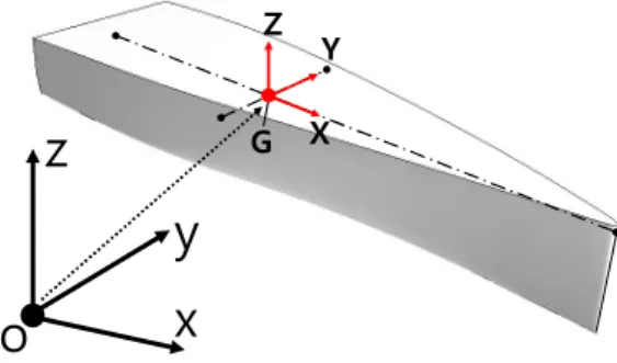
2.1 Coordinate System
The coordinate systems that used in numerical analysis are Space-fixed coordinate system and Body-fixed coordinate system in Fig. 1.
o z
y x
G Z Y
X
Fig. 1. Definition of the coordinate systems.
Space-fixed coordinate system is coordinate system of outer region for numerical towing tank and defines that surface of and are the free surface of numerical towing tank and the vertical direction of coordinate system respectively.
Body-fixed coordinate system is coordinate system of inner region for the motion of ship hull and has its origin at the center of gravity of the ship. and are oriented to the bow direction and the vertical direction respectively.
2.2 Governing Equations
The governing equations of unsteady, incompressible and
viscosity fluid that adopted here are continuity and Reynolds Averaged Navier-Stokes Equations (RANS) in Eqs. 1~3.
∙ (1)
∙
(2)
∇ ∇ ′′ (3)
Where and are the surface area vector and the control volume respectively. and are the time and the velocity vector respectively. and are the velocity vector of the surface area vector according to motion of the control volume and the body force vector respectively. and are the element surface area vector and the element vector respectively. is the stress tensor, is the constant tensor.
and ∇ are the Reynolds number and the gradient respectively. ∙ and ′′ are the transpose of a matrix and the Reynolds stress respectively.
Ship hull can be approximated as a rigid body which can move in three dimensions and rotate around three axes of body-fixed coordinate system, see in Fig. 2.
TZ
G
RY
TY
RZ
TX
RX
Fig. 2. Definition of the 6-DoF in a rigid body.
The translations of a vessel along the , and axis are referred to as surge, sway and heave motions, respectively, while the rotations around the same axis are termed roll, pitch and yaw motions. Accordingly, the sinkage is affected by heave motion while the trim angle is related to pitch motion.
For a rigid body, the translational motion of the center of gravity is described by Newton’s second law in Eq. 4.
(4)
Where is the mass, is the velocity and is the sum of forces acting on a rigid body. The rotation of the body, expressed in body-fixed coordinate system, is described by Euler’s equations in Eq. 5.
Ω
Ω × ∙ Ω (5)
Where Ω is the angular velocity of a rigid body and is the resultant torque acting on a rigid body. is the tensor of the moments of inertia and it is expressed in Eq. 6.
(6)2.3 Numerical Model
Commercial code used in this simulation is STAR-CCM+, the governing equations of fluid based on Finite Volumes Methods are discretized (Rosenfeld and Kwak, 1991; Orihara and Miyata, 2003). Integral form of RANS equations is represented as Eq. 7.
∇
(7)Each term of this equation is composed of unsteady, convection, diffusion and source term in sequence. And where and are diffusion coefficient and source term respectively.
The physical model is based on the mass and momentum conservation equations. The fluid is considered viscous and incompressible. The SST turbulence model (Menter, 1994) used is known to predict precise results of boundary layer, such as adverse pressure gradients and separation flow.
All Wall Treatment used for the wall modelling. The problem is closed establishing the initial and boundary conditions on the physical and computational boundaries. The spatial discretization of the convective terms is done with a second order upwind based scheme, whereas the temporal discretization is chosen with a second order upwind scheme for transient problems.
Velocities and pressures are solved in a segregated manner, and then coupled by means of the SIMPLE algorithm. A second-order backward Euler scheme is applied for temporal discretization and the time-step was set to 0.001s.
The volume of Fluid (VOF) method with artificial compression technique is applied for locating and tracking the free surface (Hirt and Nichols, 1981). In the VOF method, each of the two-phase is considered to have a separately defined volume fraction (), where 0 and 1 represent that the cell is filled with air and water respectively and stands for the interface between two-phase fluid. The density and dynamic viscosity for the mixed fluid can be presented as Eqs. 8~9.
(8)
(9)
An important quality of an immiscible phase mixture is that the fluid components always remain separated by a sharp interface. However, VOF method causes solution smearing. So, it is important to suppress the smearing at the interface and prevent the occurrence of an unphysical interface shape. To overcome this phenomenon, the High-Resolution Interface Capturing (Muzaferiha et al., 1998) scheme is used to mimic the convective transport of immiscible fluid components.
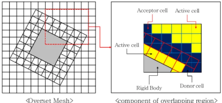
2.4 Overset Grid Method
Two overlapping regions, one is inner region for the motion of a rigid body and the other is outer region for the numerical towing tank, are used in overset method on STAR-CCM+ and this is shown in Fig. 3.
Rigid Body
Active cell
Donor cell Active cell
Acceptor cell
<Overset Mesh> <component of overlapping region>
Fig. 3. Overset Grid Method.
using Side Appendages In an overset mesh, cells are grouped into active, inactive,
acceptor and donor cells. Within active cells, discretized governing equations are solved. Within inactive cells, no equation is solved, however, these cells can become active if the overset region is moving. Acceptor cells are attached to the overset boundary in the outer region and donor cells is the overset boundary cells in the inner region. These cells are used to couple solutions on the two overlapping regions. Variable values like a fluid velocity, pressure and motion of a rigid body at donor cells of the inner region express variable values at acceptor cells in the outer region, through interpolation (CD-ADAPCO, 2016).
The donor and acceptor cells transfer information between the meshes. Each acceptor cell has one or more donor cells.
Choosing the donor cells can be done differently, the method used in this study is linear interpolation. Details of the 6-DOF module with overset grid method can be found in David Frisk and Linda Tegehall (2015).
Conclusively, key features of numerical model that explained above is listed in Table 1.
Model
Governing Equation Reynolds-Averaged Navier-stokes
Time Implicit Unsteady
Temporal Discretization Second-Order Upwind Turbulent Model SST (Menter)
Wall Treatment All Y+ Treatment Spatial Discretization Cell Centered FVM Velocity/Pressure Coupling SIMPLE Algorithm Multiphase Model VOF (Volume of Fluid) Free Surface Problem HRIC Schemes
Body motion Dynamic Fluid-Body Interaction Overset Grid Method Table 1. Key features of numerical model
3. Computational Overviews
3.1 Geometry Modelling
The planing hull studied in this paper is second hull form of Wave-Piercing High-speed Planing Hull(WPPH-2nd). The geometry model with spray rail and hard chine in the present study is from Kim (2017) and shown in Fig. 4.
(a) Case : 1 Bare hull
0.5LBP
(b) Case 2 : 0.5L Spray rail 7%B / 10°
(d) Case 4 : 1L Hard chine LBP
3%B / 0°
0.75LBP
7%B / 10°
(c) Case 3 : 0.75L Spray rail
Fig. 4. Geometric representation of WPPH-2nd.
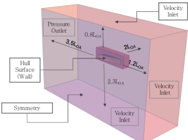
3.2 Computational Domain and Boundary Conditions The computational domain and boundary conditions are illustrated in Fig. 5. The computational domain consists of moving overset region and stationary background region and its dimensions are expressed in terms of the overall hull length, LOA. These dimensions agree well with the minimum recommendations of ITTC (2011). And each case was set in experimental trim and sinkage condition for faster convergence.
Velocity Inlet Pressure
Outlet
Velocity Inlet
Velocity Inlet Hull
Surface (Wall)
Symmetry
0.8LOA
2.3LOA
Fig. 5. Computational domain and boundary condition.
At the inlet, located in front of the hull, the velocity of the incident air and water was set to hull speed. The outlet was set to a pressure outlet. At top and bottom of the computational domain was also set to velocity inlet and volume fraction of air and water in each boundary for physical continuity. To use overset method, overset condition was set to boundary of moving part.
3.3 Mesh Configuration
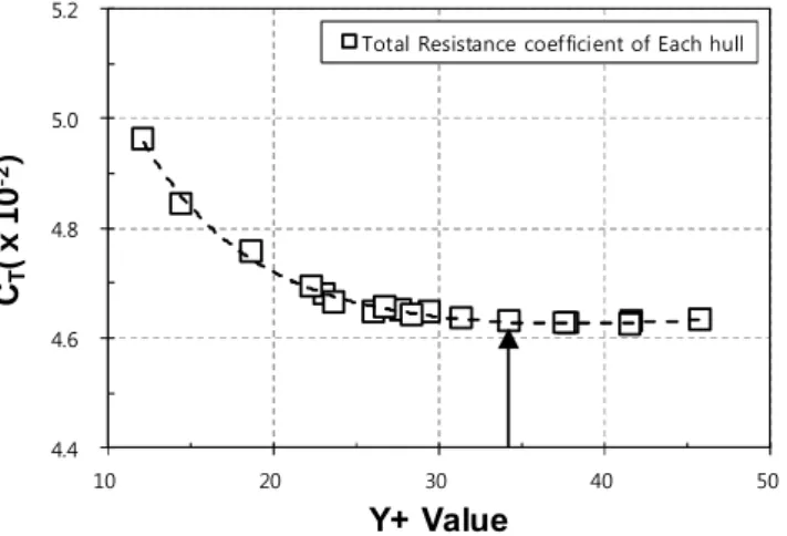
In Fig. 6, the structure of STAR-CCM+ mesh is illustrated and the mesh density was focused on certain regions of the domain to capture the important flow phenomena around the ship hull. First, fine mesh was used on the hull surface and prism
layers were created along the hull to resolve the boundary layer and to obtain correct shear stresses on the hull. The prism layers were constructed with a total thickness corresponding to the estimated boundary layer thickness, and the height of the first cell layer was set to obtain a ≈ from Study in Fig. 7.
(a) Free surface (b) Overset / Free surface Region Free surface Region
Overset Region
Fig. 6. Schematic illustrations of the STAR-CCM+ mesh.
4.4 4.6 4.8 5.0 5.2
10 20 30 40 50
Total Resistance coefficient of Each hull
CT(ⅹ10-2)
Y+ Value
Fig. 7. Total resistance Coefficient Comparison varying with .
The mesh constructed in STAR-CCM+ was divided into one stationary background region and one moving overset region close to the hull. Both parts were meshed with trimmed, predominantly hexahedral cells with local refinements at the free surface and the wake. In the overlapping region were of the same size and formed a continuous layer around the overset region. To resolve the free surface accurately, a high mesh density was used in the region around the free surface in vertical direction where induced wakes by hull were expected to be present. Outside these regions, the mesh was coarser. The whole mesh consists of a total of about 2.16 million of cells, where the inner region has about 898,000 cells and the outer region has about 1,268,000.
4. Results and Discussion
4.1 CFD Validation and Characteristics of WPPH-2nd The use of commercial code when securing its reliability requires a validation of existing experimental results. In this paper, the results from the WPPH-2nd, are used to validate the CFD model by comparing with the experimental measurements.
Table 2 lists the principle dimension of WPPH-2nd whilst Fig. 8 illustrates the body plans of the model.
Zero point
DWL Top line
Fig. 8. Body plans of WPPH-2nd.
Dimensions Parent Hull Model
Scale 1 11.429
Length over all(m) 8.000 0.700
Breath(m) 2.3 0.201
Depth(m) 1.2 0.105
Draft(m) 0.326 0.028
LCG(m) 2.648 0.272
VCG(m) 0.688 0.048
Wetted Surface Area(m2) 12.619 0.096
Disp.(Ton) 2.286 1.531 × 10⁻³
Table 2. Principal dimension of WPPH-2nd
, Volume Froude Number, is a dimensionless parameter, shown by the Eq. 10, which widely used in planing hull because its waterline changes largely as running attitudes (Blount, 2014).
∇
(10)
Where is hull speed, ∇ is displacement volume and
using Side Appendages
is the gravity acceleration. CFD validation was carried out for a wide range of hull speed in planing condition ( ), and the range of reynolds number is
× × . The results were compared with experimental data of the resistance coefficient, trim and sinkage give in Figs. 9~11. The overall numerical prediction of the resistance and trim angle are similar with experiment, however, it shows that there are overestimation of the total resistance in the region of qualitatively and underestimation of the trim angle all range of quantitatively. The numerical prediction of the Sinkage is similar quantitatively, however, its qualitative trend doesn’t correspond with experimental data.
0.0 3.0 6.0 9.0 12.0 15.0
3.0 3.5 4.0 4.5 5.0
WPPH-EXP.
WPPH-CFD
Fnv CT(ⅹ10-3)
Fig. 9. Comparison of resistanceAverage coefficient.
0.0 2.0 4.0 6.0 8.0 10.0
3.0 3.5 4.0 4.5 5.0
WPPH-EXP.
WPPH-CFD
Trim(°)
Fnv
Fig. 10. Comparison of trim angleAverage.
-4.0 -2.0 0.0 2.0 4.0
3.0 3.5 4.0 4.5 5.0
WPPH-EXP.
WPPH-CFD
Sinkage(cm)
Fnv
Fig. 11. Comparison of sinkageAverage.
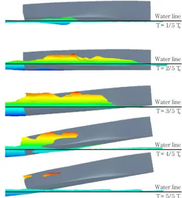
The overestimation of the total resistance that had calculated is confirmed in Fig. 12 which represents the side spray excessively extends to the aft side over 2/5~4/5 period. It is confirmed that wetted surface area was changed periodically due to the viscosity of the water and soft chine.
Water line T = 1/5 Te
Water line T = 2/5 Te
Water line T = 3/5 Te
Water line T = 4/5 Te
Water line T = 5/5 Te
Fig. 12. Motion of WPPH-Bare hull when .
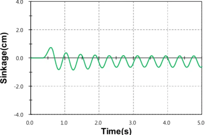
In other words, the additional resistance, that is shown after
is generated periodically on the ship hull due to the porpoising and can be seen in Figs. 13~18. Trim and sinkage
displayed periodic oscillations of about 0.2~0.25 seconds, and their amplitude increased as hull speed increased. This phenomenon would have negative effect in bow waves conditions because it can cause resonance phenomenon with same period of wave.
Therefore, side spray and porpoising should be suppressed.
-6.0 -3.0 0.0 3.0 6.0
0.0 1.0 2.0 3.0 4.0 5.0
Trim(°)
Time(s)
Fig. 13. Time history of pitch motion at .
-6.0 -3.0 0.0 3.0 6.0
0.0 1.0 2.0 3.0 4.0 5.0
Trim(°)
Time(s)
Fig. 14. Time history of pitch motion at .
-6.0 -3.0 0.0 3.0 6.0
0.0 1.0 2.0 3.0 4.0 5.0
Trim(°)
Time(s)
Fig. 15. Time history of pitch motion at .
-4.0 -2.0 0.0 2.0 4.0
0.0 1.0 2.0 3.0 4.0 5.0
Sinkage(cm)
Time(s)
Fig. 16. Time history of heave motion at .
-4.0 -2.0 0.0 2.0 4.0
0.0 1.0 2.0 3.0 4.0 5.0
Sinkage(cm)
Time(s)
Fig. 17. Time history of heave motion at .
-4.0 -2.0 0.0 2.0 4.0
0.0 1.0 2.0 3.0 4.0 5.0
Sinkage(cm)
Time(s)
Fig. 18. Time history of heave motion at .
4.2 Motion and Resistance Characteristics with Appendages Numerical analysis was performed with the appendages to suppress this phenomenon. For comparing this phenomenon quantitatively, the RMS value is the square root of the arithmetic
using Side Appendages mean of the square of the function that defines the continuous
waveform. The corresponding formula for a continuous waveform
defined over the interval is Eq. 11.
s
(11)
The RMS values are compared to evaluate the amplitude of the periodic motion in Figs. 19~20.
0.0 1.0 2.0 3.0 4.0 5.0
3.8 4.1 4.3 4.6 4.8
WPPH-Bare hull WPPH-0.5L Spray rail WPPH-0.75L Spray rail WPPH-1L Chine
TrimRMS(°)
Fnv
Fig. 19. Comparison of Trim angleRMS.
0.0 0.6 1.2 1.8 2.4 3.0
3.8 4.1 4.3 4.6 4.8
WPPH-Bare hull WPPH-0.5L Spray rail WPPH-0.75L Spray rail WPPH-1L Chine
SinkageRMS(cm)
Fnv
Fig. 20. Comparison of SinkageRMS.
It can be seen that the RMS values of pitch and heave motion occur little at and increase sharply in
. In general, the RMS value significantly decrease compared to the bare hull when appendages are applied.
But porpoising can’t suppress perfectly with these appendages.
The 0.5 L spray rail is suppressed to 24-55 % in the pitch
motion and 33-55 % in the heave motion. It is confirmed that the spray rail effectively suppressed the porpoising than the hard chine, except the RMS value of the 0.75 L spray rail were slightly larger than others in .
Water line T = 1/5 Te
Water line T = 2/5 Te
Water line T = 3/5 Te
Water line T = 4/5 Te
Water line T = 5/5 Te
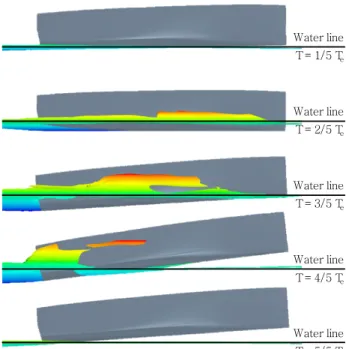
Fig. 21. Motion of WPPH-0.5L Spray rail when .
Water line T = 1/5 Te
Water line T = 2/5 Te
Water line T = 3/5 Te
Water line T = 4/5 Te
Water line T = 5/5 Te
Fig. 22. Motion of WPPH-0.75L Spray rail when .
Water line T = 1/5 Te
Water line T = 2/5 Te
Water line T = 3/5 Te
Water line T = 4/5 Te
Water line T = 5/5 Te
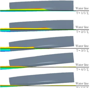
Fig. 23. Motion of WPPH-1L Hard chine when .
The motions of WPPH with various appendages and its spray scenes can be seen in Figs. 21~23. Fig. 21 and 22, shows that when spray occurs forward these spray rails’ position, spray extends excessively through the hull side in 2/5~4/5 period, and these spray rails are unable to function. However, unlike spray rail, 1L hard chine suppress spray effectively, and it is considered that it is effective to set the angle of appendages to be less than 0° in order to suppress wave.
5. Conclusions and future works
In present work, a detailed analysis of the main flow features and of the performances of the wave-piercing high-speed planing hull has been carried out by commercial software, STAR-CCM+.
Base on the computed results of STAR-CCM+ seem sufficiently adequate for the prediction of the performances of planing hulls on calm water in planing conditions. It is confirmed that the dynamic instability phenomena in pitch and heave motions (Porpoising) occurred after a certain , and effectively suppressed using some of appendages, especially the 0.5L spray rail is suppressed to 24-55 % in the pitch motion and 33-55 % in the heave motion. In case of suppressing spray, the hard chine suppress spray effectively when the angle of appendages set to be less than 0° in order to suppress wave.
Future studies will require additional research to effectively
control the porpoising of WPPH with stern appendages and based on this research, it is necessary to study on the seakeeping assessment of WPPH in wave conditions.
Acknowledgements
This research was performed with the support of the Ministry of Maritime Affairs and Fisheries’ Future Maritime Commercial Technology Development Project under the theme of
“Development of wave-stable high speed leisure boat for global market advance” (20140112) and the Ministry of Education and the National Research Foundation of Korea’s Element design technology development of Marine Tourism Control Patrol Type High-speed government vessel for modernization Promotion (2015H1C1A1035813).
References
[1] Blount, D. L.(2014), Performance by Design: Hydrodynamics for High-Speed Vessels, USA, pp. 317-320.
[2] Calderon, A. and L. Hedd(2011), Theoretical and Experimental Investigation on Resistance of Transonic Hull, Proceeding of 9th HSMV, Naples, pp. 25-27.
[3] CD-ADAPCO(2016), STAR-CCM+ User Guide, Version 11.04.010, http://steve.cd-adapco.com.
[4] Frisk, D. and L. Tegehall(2015), Prediction of High-Speed Planing Hull Resistance and Running Attitude, Thesis for the Degree of Master of Science, pp. 20-21.
[5] Hirt, C. W. and B. D. Nichols(1981), Volume of Fluid (VOF) Method for the Dynamics of Free Boundaries, Journal of Computational Physics, 39, pp. 201-225.
[6] ITTC(2011), International Towing Tank Conference, 26th ITTC Specialist Committee on CFD in Marine Hydrodynamics.
Practical Guidelines for Ship CFD Simulations, Technical report 7.5-03-02-03. Revision 01, p. 5.
[7] Jeong, U. C., D. K. Lee and K. S. Jung(2016), Study of Hull Form Development of Wave-Piercing-Type High-Speed Planing Boat, Journal of Ocean Engineering and Technology Vol. 30, No. 2, pp. 69-74.
[8] Keuning, J. A., J. Pinkster and F. Van Walree(2002), Further Investigations into the Hydrodynamic Performance of the AXE Bow Concept, Proceedings of the 6th Symposium on High Speed Marine Vehicles (HSMV 2002), Castello di baia, Italy, http://www.marin.nl/web/Publications/Publication-items
using Side Appendages /Further-investigation-into-the-hydrodynamic-performance-of-th
e-AXE-Bow-Concept.htm.
[9] Kim, D. H., I. D. Seo, K. P. Rhee, N. W. Kim and J. H.
Ahn(2015), A model Test Study on th Effect of the Stern Interceptor for the Reduction of the Resistance and Trim Angle for Wave-piercing Hulls, Journal of the Society of Naval Architects of Korea, Vol. 52, No. 6, pp. 485-493.
[10] Kim, S. W.(2017), A Numerical Investigation on Motion Control of Wave-Piercing High-Speed Planing Craft in Calm Water using Appendages, Thesis for the Degree of Master of Science, p. 52.
[11] Menter, F. R.(1994), Two-Equation Eddy-Viscosity Turbulence Models for Engineering Applications, AIAA Journal, Vol.
32, No. 8, pp. 1598-1605.
[12] Muzaferija, S., M. Peri, P. C. Sames and T. E. Schellin (1998), A Two-Fluid Navier-Stokes Solver to Simulate Water Entry. Proceedings of the 22th symposium on naval hydrodynamics. Washington, DC, pp. 638-650.
[13] Orihara, H. and H. Miyata(2003), Evaluation of added resistance in regular incident waves by computational fluid dynamics motion simulation using an overlapping grid system, Journal of Marine Science and Technology, Vol. 8, No. 2, pp. 47-60.
[14] Rosenfeld, M and D. Kwak(1991), Time-dependent solutions of viscous incompressible flows in moving coordinates, International Journal for Numerical Methods in Fluids, 13(10), pp. 1311-1328.
[15] Thompson, A.(1997). BOAT, United States Patent, Patent No.:6116180, https://www.google.com/patents/US6116180.
Received : 2017. 05. 12.
Revised : 2017. 05. 26.
Accepted : 2017. 05. 29.