A COMPARATIVE STUDY OF THE 1-PIECE AND 2-PIECE CONICAL ABUTMENT JOINT :
THE STRENGTH AND THE FATIGUE RESISTANCE
Taek-Ka Kwon1, D.D.S., M.S.D., Jae-Ho Yang2, D.D.S., M.S.D., Ph.D.,
Sung-Hun Kim3, D.D.S., M.S.D., Ph.D., Jung-Suk Han4, D.D.S, M.S.D., Ph.D., Jai-Bong Lee5, D.D.S., M.S.D., Ph.D.
1Graduate student, Department of Prosthodontics, School of Dentistry, Seoul National University
2Professor, Department of Prosthodontics, School of Dentistry, Seoul National University
3Assistant Professor, Department of Prosthodontics, School of Dentistry, Seoul National University
4Associate Professor, Department of Prosthodontics, School of Dentistry, Seoul National University
5Professor, Department of Prosthodontics, School of Dentistry, Seoul National University
Statement of problem. The performance and maintenance of implant-supported prosthe- ses are primarily dependent upon load transmission both at the bone-to-implant interface and within the implant-abutment-prosthesis complex. The design of the interface between com- ponents has been shown to have a profound influence on the stability of screw joints.
Purpose. The Purpose of this study was to compare the strength and the fatigue resistance of 1- piece and 2-piece abutment connected to oral implant, utilizing an internal conical interface.
Material and methods. Twenty Implatium�tapered implants were embedded to the top of the fixture in acrylic resin blocks. Ten Combi�(1-piece) and Dual�(2-piece) abutments of the same dimension were assembled to the implants, respectively. The assembled units were mount- ed in a testing machine. A load was applied perpendicular to the long axis of the assemblies and the loading points was at the distance of 7mm from the block surface. Half of 1-piece and 2-piece abutment-implant units were tested for the evaluation of the bending strength, and the others were cyclically loaded for the evaluation of the fatigue resistance until plastic deformation occurred. Nonparametric statistical analysis was performed for the results.
Results. Mean plastic and maximum bending moment were 1,900±18Nmm, 3,609±
106Nmm for the 1-piece abutment, and 1,250±31Nmm, 2,688±166Nmm for the 2-piece abut- ment, respectively. Mean cycles and standard deviation when implant-abutment joint showed a first plastic deformation were 238,610±44,891. cycles for the 1-piece abutment and 9,476±
3,541 cycles for the 2-piece abutment.
A 1-piece abutment showed significantly higher value than a 2-piece abutment in the first plastic bending moment (p<.05), maximum bending moment (p<.05) and fatigue strength (p<.05).
Conclusion.Both 1-piece and 2-piece conical abutment had high strength and fatigue resistance and this suggests long-term durability without mechanical complication. However, the 1-piece conical abutment was more stable than the 2-piece conical abutment in the strength and the fatique resistance.
Key Words
J Korean Acad Prosthodont : Volume 45, Number 6, 2007
S
everal reports have emphasized the integri- ty of bone/implant interface and endorsed the long-term effectiveness of osseointegrated tech- nique in the oral cavity.1-3The use of osseointe- grated dental implants had become a successful procedure for the treatment of complete,1partial4 edentulism, and single-tooth replacements in both the anterior and posterior regions of the mouth.5-7One commonly reported mechanical problem that affects single-tooth implant replace- ments is screw joint instability, specifically, loos- ening or fracture of the abutment or retaining screws.5-7The etiology of screw joint instability has been identified by Glantz et al.8, who observed the high bending moments were recorded even when loads were placed close to centric occlusion.
This suggests the such moments should be accom- modated by the joint design, within the limits of normal masticatory load. In several study, it was shown that the internal conical joint was a sig- nificantly more stable joint when compared to an external hexagonal or butt joint.9,10
Norton11compared the static bending strength between 1-piece and 2-piece Astra Tech�abutments (Astra Tech AB, Mo¨lndahl, Sweden). He con-
cluded the 2-piece abutments did not detract the bending resistance of their 11-degree internal- cone joint. but, 1-piece and 2-piece Astra Tech� abutments were not of the same dimension. Even 2-piece abutments showed significantly higher maximum bending strength. It’s the reverse to the author’s hypothesis.
Khraisat et al.12compared the ultimate fatigue resistance of CeraOne�and solid abutments con- nected to single Branemark�and ITI�implants, respectively. It showed that the fatigue strength of the ITI�implant-abutment complex was sig- nificantly better than the Branemark�implant- abutment complex. More recently, a compari- son study13of the fatigue resistance of solid and SynOcta� abutments connected to single ITI implants was shown that solid abutments possess higher removal torque resistance than synOcta� abutments when connected to synOcta�ITI� implants.
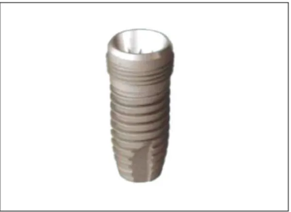
Implatium�tapered implants (Dentium, Seoul, South Korea) (Fig. 1) are submerged-type root-form implants and utilize 11-degree internal conical inter- face the same as Astra Tech�implants. Combi�(1- piece) and Dual�(2-piece) abutments are made of the same dimension and connected to the fixture for the cement-retained superstructures. But,
Fig. 1. Implantium�tapered implant (Dentium, Seoul, South Korea).
Fig. 2.Dual�(2-piece, left) and Combi�(1-piece, right) abutment.
Dual�(2-piece) abutments with an internal hexa- gon can resist against rotation(Fig. 2, 3).
The Purpose of this study was to compare the strength and the fatigue resistance of 1-piece and 2-piece Dentium�abutments under lateral sta- tic and dynamic loads.
MATERIAL AND METHODS
1. Implant specimens and abutments
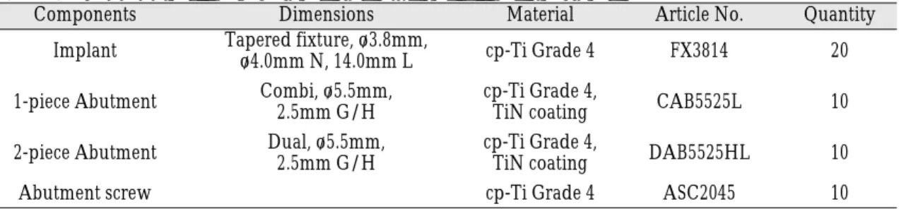
This study used 10 assemblies of 2 abutment sys- tems: A solid 1-piece Combi�and a hollow 2-piece Dual�(Dentium, Seoul, South Korea) abutment with an internal hex (Fig. 2). Each of the implant- abutment groups and the corresponding com- ponents were delivered from commercially avail- able stock (Table I).
Twenty Implatium� tapered implants were embedded to the top of the fixture in acrylic resin blocks which were prepared by heating the mixture of the powder and the liquid (Ortho- Jet; Lang Dental Mfg. Co., Il, USA) under pressure.
These preparations were standardized and utilized with prefabricated mounting jig, corresponding components and PERform Inkovac� pres- sure/vacuum polymerization unit (Hedent GmbH, Oberursel, Germany).
Ten Combi�(1-piece) abutments and ten Dual�
(2-piece) abutments were connected to twenty Implatium�tapered fixtures and tightened to 35Ncm with a torque wrench supplied by man- ufacturer just before the loading tests.
2. Loading machine and loading approach
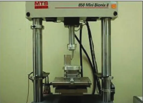
Each specimen was firmly mounted in a cus- tomized stainless steel jig of a programmable hydraulic loading machine (MTS 858 mini bion- ix Ⅱ; MTS system Co., Minnesota, USA) (Fig. 4) which controlled by Teststar�Ⅱ (MTS system Co., Minnesota, USA) and programmed with Station manager�(MTS system Co., Minnesota, USA).
The loading was applied perpendicularly to the flat surface of the underlying abutment and the loading point was 7mm distant from the block surface which is maintained by the 7mm thick customized stainless steel bar (Fig. 5).
2.1. Cantilever bending tests
High load tests were run, with increading force and a constant velocity of 0.1mm/sec until such time as the applied load caused a failure of the unit, or maximum load was achieved.
First point of plastic deformation was defined as 0.5mm of permanent displacement, as measured by the Station manager�. This deformaion was sim-
Table I. Components and dimensions of the tested specimens
Components Dimensions Material Article No. Quantity
Implant Tapered fixture, o/3.8mm, cp-Ti Grade 4 FX3814 20
o/4.0mm N, 14.0mm L
1-piece Abutment Combi, o/5.5mm, cp-Ti Grade 4, CAB5525L 10
2.5mm G/H TiN coating
2-piece Abutment Dual, o/5.5mm, cp-Ti Grade 4, DAB5525HL 10
2.5mm G/H TiN coating
Abutment screw cp-Ti Grade 4 ASC2045 10
N : neck, L : length, G/H : gingival height, cp-Ti : commercially pure titanium
ilarly determined to be sure of its plastic nature, yet small enough to be of clinical relevance by a previous study.10,11
This test was repeated 5 times for each abutment under scrutiny.
2.2. Cyclic loading tests
Cyclic loading of peak loads of 200N and valley loads of 0N with compressive sine wave was applied on the abutments at 14Hz until the first plastic deformation was occurred. This test was also repeated 5 times for each abutment.
3. Statistical analysis
Results were subjected to statistical analysis means by the nonparametric Mann-whitney rank-sum U tests in order to determine the sig- nificance of differences between the 2 independent groups. All tests were performed 2-tailed and at the 5% significance level.
RESULTS
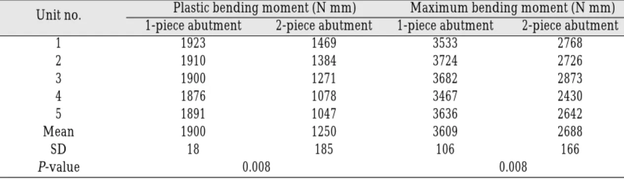
Table II gives the results of the cantilever bend- ing test for each unit with the 1-piece and the 2- piece abutments. Point of first plastic deforma-
tion and maximum bending moment are record- ed in Nmm. Figure 6 and 7 show typical graphs recorded for each abutment design.
The first point at which permanent plastic deformation was recorded for the 1-piece abutment was at a mean moment of 1,900Nmm (load=317N), which compared to a mean moment of 1,250Nmm (load=208N).
A mean maximum bending moment of 3,609Nmm (load=601N) was recorded for the 1- piece abutments compared to a mean maximum bending moment of 2,688Nmm (load=448N) for the 2-piece abutments.
The nonparametric Mann-whitney rank-sum U tests showed a significant difference between the 2 groups (P=0.008, 0.008) in the moment of the first plastic deformation and the maximum bend- ing moment.
In each case the units were dismantled in order to detect where the fracture or large plastic defor- mation had occurred. For the 1-piece abutment, the point of plastic deformation or critical zone was the conical collar of the fixture, the internal cone of the abutment and the neck of abutment screw, while for the 2-piece abutment, the deformation was noted at the conical collar of the fixture and the neck of the abutment screw (Fig. 8).
Fig. 4.MTS 858 mini bionix II. Fig. 5.Loading the specimen.
Table III shows the result of the cyclic loading tests of the both groups. 1-piece abutment group showed first plastic deformation between 163,950 and 279,125 cycles with a standard deviation of 44,891 cycles, whereas 2-piece abutment group showed first plastic deformation between 5,330 and 13,100 cycles with a standard deviation of 3,542 cycles. The peak/ valley value of the displacement of the abutment maintained constantly just before the plastic deformation and then the peak/ val- ley value was increased and the amplitude of the displacement wave was amplified in both groups.
The nonparametric Mann-whitney rank-sum U test showed a significant difference between the 2 groups (P=0.008).
Table II. Results from the cantilever bending test
Unit no. Plastic bending moment (N mm) Maximum bending moment (N mm) 1-piece abutment 2-piece abutment 1-piece abutment 2-piece abutment
1 1923 1469 3533 2768
2 1910 1384 3724 2726
3 1900 1271 3682 2873
4 1876 1078 3467 2430
5 1891 1047 3636 2642
Mean 1900 1250 3609 2688
SD 18 185 106 166
P-value 0.008 0.008
SD : standard deviation
Fig. 6. Cantilever bending performance of a Combi (1-piece) abutment.
Fig. 7. Cantilever bending performance of a Dual (1- piece) abutment.
Fig. 8. Critical zone.
Left (Combi, 1-piece) : (a) internal cone of the abutment (b) neck of abutment screw (c) conical collar of the fixture
Right (Dual, 2-piece) : (d) neck of abutment screw (e) con- ical collar of the fixture.
a
b d
c e
DISCUSSION
There have been few comparison studies about the relative strength and fatigue resistance of 1- piece and 2-piece conical abutment design. In a recent comparative study,113-point bending strengths of 1-piece and 2-piece Astra Tech� abutments (Astra Tech AB, Mo¨lndahl, Sweden) were recorded with no significant differency in their 11-degree internal-cone joint. Even 2-piece abut- ments showed significantly higher maximum bending strength. but, 1-piece and 2-piece Astra Tech�abutments were not of the same dimension and the fixtures were screwed into a rigid beam, including conical collar, which might be influence the resistance of conical collar to the bending moment. In this study, the fixtures were embed- ded in acrylic resin block, which might be influ- ence less than the rigid beam.
Recently, another comparison study13of the fatigue resistance of solid and SynOcta�abutments connected to single ITI implants was shown that solid abutments possess higher removal torque resistance than synOcta�abutments when con- nected to synOcta�ITI�implants, which is cor- responded to this study. The period of the steady peak/valley value in the displacement wave
might be the time of losing the preload and the fric- tion.
In this study, cyclic loading of peak loads of 200N and valley loads of 0N with compressive sine wave was applied on the abutments. The peak load of 200 N was equivalent to the lateral component of 400 N vertical force on a 20-degree cusp inclina- tion to the implant longitudinal axis. 400 N ver- tical force was the somewhat higher value than the average one of maximal posterior occlusal force for fixed prosthesis supported by implant.14In a pilot study of this study, cyclic loading of 150 N peak loads of 5,000,000 cycles at 14Hz was per- formed in both 1-piece and 2-piece groups, but no plastic deformation was observed through the whole cycles. Therefore higher loading test was set up to compare the fatigue resistance between the 1-piece and 2-piece abutment.
The critical zone was the conical collar of the fix- ture, the internal cone of the abutment and the neck of abutment screw for the 1-piece abutment, while for the 2-piece abutment, the deformation was observed at the conical collar of the fixture and the neck of the abutment screw. The inspection of the critical zones indicates that in 1-piece group 3 parts resist the bending moment, in the case of 2-piece abutment only 2 parts resist. Therefore 1- Table III. Results from the cyclic loading test
Unit no. Plastic deformation cycles
Combi (1-piece) abutment Dual (2-piece) abutment
1 235,900 5,330
2 163,950 11,850
3 248,125 13,100
4 265,950 6,050
5 279,125 11,050
Mean 238,610 9,476
SD 44,891 3,542
P-value 0.008
SD : standard deviation
piece group could show better resistance to the bending moment.
CONCLUSION
Within the limitation of this study, the follow- ing conclusion were drawn:
1. Both 1-piece and 2-piece conical abutment have high strength and fatigue resistance and thus function for years without mechanical com- plication.
2. The 1-piece conical abutment joint shows higher strength than the 2-piece conical abut- ment joint.
3. The 1-piece conical abutment joint displays higher fatigue resistance than the 2-piece conical abutment joint.
REFERENCES
1. Adell R, Eriksson B, Lekholm U, Branemark PI, Jemt T. Long-term follow-up of osseointegrated im- plants in the treatment of totally edentulous jaws.
Int J Oral Maxillofac Implants 1990;5:347-59.
2. Cochran DL. The scientific basis for and clinical ex- periences with Straumann implants including the ITI Dental Implant System: a consensus report. Clin Oral Implants Res 2000;11(Suppl):33-58.
3. Bahat O. Branemark system implants in the pos- terior maxilla: clinical study of 660 implants followed for 5 to 12 years. Int J Oral Maxillofac Implants 2000;15:646-53.
4. Jemt T, Linden B, Lekholm U. Failures and com- plications in 127 consecutively placed fixed partial prostheses supported by Branemark implants:
from prosthetic treatment to first annual checkup.
Int J Oral Maxillofac Implants 1992;7:40-4.
5. Jemt T, Lekholm U, Grondahl K. 3-year follow
up study of early single implant restorations ad modum Branemark. Int J Periodontics Restorative Dent 1990;10:340-9.
6. Scheller H, Urgell JP, Kultje C, Klineberg I, Goldberg PV, Stevenson-Moore P, et al. A 5-year multicen- ter study on implant-supported single crown restorations. Int J Oral Maxillofac Implants 1998;13:212-8.
7. Jemt T, Pettersson P. A 3-year follow-up study on single implant treatment.J Dent 1993;21:203-8.
8. Glantz PO, Rangert B, Svwnsson A, Stafford GD, Arnvidarson B, Randow K, Linden U, Hulten J. On clinical loading of osseointegrated implants. A methodological and clincal study. Clin Oral Implants Res 1993;4:99-105.
9. Mollersten L, Lockowandt P, Linden LA.
Comparison of strength and failure mode of sev- en implant systems: an in vitro test. J Prosthet Dent 1997;78:582-91.
10. Norton MR. An in vitro evaluation of the strength of an internal conical interface compared to a butt joint interface in implant design. Clin Oral Implants Res 1997;8:290-98.
11. Norton MR. An in vitro evaluation of the strength of a 1-piece and 2-piece conical abutment joint in implant design. Clin Oral Implants Res 2000;
11:458-64.
12. Khraisat A, Stegaroiu R, Nomura S, Miyakawa O.
Fatigue resistance of two implant/abutment joint designs. Journal of Prosthetic Dentistry 2002;88:
604-10
13. Çehreli MC, Akça K, I·plikçioğlu H, S¸ahin S.
Dynamic fatigue resistance of implant-abutment junction in an internally notched morse-taper oral implant: influence of abutment design. Clin Oral Implants Res 2004;15:459-65.
14. Mericske-Stern R, Zarb GA. In vivo measure- ments of some functional aspect with mandibular fixed prostheses supported implants. Clin Oral Implants Res 1996;7:153-61.
Reprint request to:
JAE-HOYANG, D.D.S., M.S.D., PH.D.
DEPARTMENT OFPROSTHODONTICS, GRADUATE SCHOOL, SEOULNATIONALUNIVERSITY
28, YEONGUNDONG, JONGNOGU, SEOUL,110-749, KOREA