〈학술논문〉
http://dx.doi.org/10.15231/jksc.2015.20.3.001 ISSN 1226-0959
† Corresponding Author, [email protected]
This is an Open-Access article distributed under the terms of the Creative Commons Attribution Non-Commercial License (http://creativecommons.org/licences/by-nc/4.0) which permits unrestricted non-commercial use, distribution, and reproduction in any medium, provided the original work is properly cited.
A Study on Laminar Lifted Jet Flames for Diluted Methane in Co-flow Air
Narayan P. Sapkal
*, Won June Lee
**, Jeong Park
* †and Oh Boong Kwon
**
Department of Mechanical Engineering, Pukyong National University
**
Interdisciplinary Program of Biomedical Engineering, Pukyong National University
(Received 13 May 2015, Received in revised form 20 June 2015, Accepted 22 June 2015)ABSTRACT
The laminar lifted jet flames for methane diluted with helium and nitrogen in co-flow air have been investi- gated experimentally. Such jet flames could be lifted in both buoyancy-dominated and jet momentum dominated regimes (even at nozzle exit velocities much higher than stoichiometric laminar flame speed) despite the Schmidt number less than unity. Chemiluminescence intensities of OH
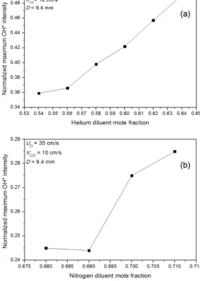
*radical (good indicators of heat release rate) and the radius of curvature for tri-brachial flame were measured using an intensified charge coupled device (ICCD) camera and digital video camera at various conditions. It was shown that, an increase in OH
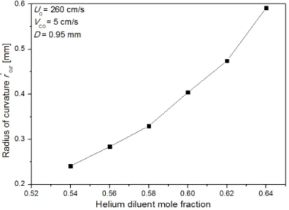
*concentration causes increase of edge flame speed via enhanced chemical reaction in buoyancy dominated regime. In jet momentum dominated regime, an increase in radius of curvature in addition to the increased OH
*concentration stabilizes such lifted flames. Stabilization of such lifted flames is discussed based on the stabilization mechanism.
Key Words : Lifted flames, Buoyancy effect, Schmidt number, Richardson number, Chemiluminescence, Radius of curvature
기 호 설 명
D : Fuel nozzle diameter
Uo : Fuel nozzle exit velocity Vco : Coflow-air velocity S
Lo: Un-stretched non-adiabatic stoichio- metric laminar burning velocity X
F,O: Initial fuel mole fraction r
cur: Radius of curvature
ρ : Gas density
g : Gravitational acceleration H
L: Liftoff height
Sc : Schmidt number Re : Reynolds number Ri : Richardson number Le : Lewis number
1. Introduction
Laminar lifted non-premixed jet flames have been widely studied[1-3], to grasp the fundamental charac- teristic of flame stabilization. The leading edge of such lifted flames consists of a lean and rich premixed flame wings and a trailing diffusion flame and referred as tri-brachial flames. The stabilization mechanism is
addressed to the balance between the propagation speed
of tri-brachial flame and local axial flow velocity. Based
on cold jet similarity solution, experimentally it was
shown that propane and n-butane fuels (Sc > 1) exhi-
bited a stable lifted flames, while no stable lifted flames
were observed for methane and ethane fuels (Sc < 1)
in free jets[1]. Also, stationary lifted flames were ob-
served for propane highly diluted with nitrogen in co-
flow jets when relatively large size nozzle with the
diameter d = O (10 mm) were used[5]. In that, results
show two distinctive lifted flame stabilization modes
in the developing and developed regions of jets depend-
ing on the initial fuel mole fraction.
Narayan P. Sapkal ․ Won June Lee ․ Jeong Park and Oh Boong Kwon 2
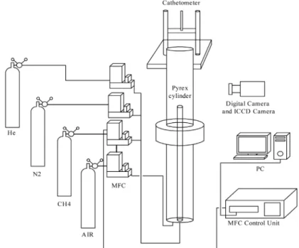
Fig. 1. Schematic experimental setup and flow system about co-flow jet burner.
Meanwhile, for the lifted flame stabilization impor- tant role of intermediate species such as OH
*, CH
2O in laminar lifted flame stabilization has been inves- tigated in hot co-flow environments[6]. Also it was recognized that OH* are the good indicators of heat release rate[7]. For a propagating triple flame, depen- dency of fuel concentration gradient upon radius of curvature addresses the correlation of edge flame speed to fuel concentration gradient[3]. The concernment of flow redirection with heat release rate was also expla- ined in detail[10]. Additionally, the tri-brachial flame speed could be sensitively dependent upon many other factors such as, mixture strength, heat loss, buoyancy, and Lewis number[11]. Motivated by this, the present study is to explore why the laminar lifted methane jet flames diluted with helium and nitrogen having (Sc <
1) can be stabilized. Richardson number Ri, is eva- luated to check the effect of buoyancy and chemilu- minescence intensities of OH* have been measured by an intensified charge-coupled device (ICCD) camera at various conditions. Also the radii of curvature, which is one of the main mechanism of the stabilization of tri- brachial flame, is measured at various conditions.
2. Experimental set-up
Experimental setup consists of a co-flow burner, a flow control system, and a visualization system as shown
in the Fig. 1. Two co-flow burners used had a central fuel nozzles with 9.4 mm and 0.95 mm inner diameters made of stainless steel and the length is 100 times of the inner diameter for the flow inside to be fully dev- eloped. A pyrex cylinder with 40 cm in length and 90.4 mm inner diameter was placed on the honeycomb, to minimize the outside disturbances. The co-flow air was supplied to the coaxial nozzle with 90.4 mm inner dia- meter through a glass beads and honeycomb for the velocity to be uniform. The fuel was a pure grade of methane diluted with the helium and nitrogen, and the compressed air was used for the co-flow. The flow rates were controlled by the mass flow controllers. The vi- sualization system consists of a digital video camera (SONY, HDR-CX560) which was triggered to capture the image of stationary lifted flame and an intensified charge-coupled device (ICCD) camera (Princeton Instru- ments, Inc. PI-MAX4:2048f) was used to visualize the behavior of lifted flame. The liftoff height was measured by the cathetometer.
3. Results and discussion
3.1. Stationary lifted flames
The change in liftoff height H
L, with fuel nozzle exit
velocity Uo, for 9.4 mm i.d. nozzle co-flow burner is
shown in the Fig. 2(a). Co-flow velocity Vco, was fixed
Fig. 2. (a) Change in liftoff height with fuel nozzle exit velocity for methane diluted with helium (Sc < 1) at various X
F,O(b) direct photographs of statio- nary lifted methane jet flame diluted with helium for Uo = 14 cm/s, at (A) X
F,O= 0.45 (B) 0.4 (C) 0.35 (D) 0.3 (E) 0.25 (F) 0.22.
to 10 cm/s. The H
Lincreases non-linearly with Uo, by addition of helium diluent and flame was blown out for 0.2 < X
F,O< 0.34. Direct photographs of lifted flames at Uo = 14 cm/s for various fuel mole fractions X
F,O, is shown in the Fig. 2(b). For diluted propane two di- fferent stabilization modes were observed in the dev- eloping and developed regions of co-flow jets. As a re- ference, the length of the developing region of free jet Z
free, was marked by dotted line. This was estimated to be Z
free/d = 0.0165 X R
ed[9], where R
edwas the Reynolds number defined as, Uod/v where v was the kinematic viscosity. Since the fuel is diluted, v was adopted with that of helium. In Fig. 2(a) nearly linearly variation has been formed in Z
freewith Uo, which further substan- tiates the two different stabilization modes in the dev- eloped and the developing regions of jet flame. Even if, the lifted flames are formed in developing and dev- eloped regions, the stabilization mechanism has to be the balance of edge flame speed to the local flow speed.
It was observed that, these flames are lifted at smal- ler nozzle exit velocities less than stoichiometric un- stretched laminar flame speeds and it was well explained by the buoyancy effect[4]. This effect of buoyancy was evaluated by the Richardson number as, Ri = ρgd/ρU
2o,
Fig. 3. (a) Change in liftoff height with fuel nozzle exit velocity for methane diluted with helium (Sc < 1) at various X
F,Oand (b) direct photographs of lifted methane jet flame diluted with helium for Uo = 260 cm/s, at (A) X
F,O= 0.6 (B) 0.56 (C) 0.52 (D) 0.48 (E) 0.44 (F) 0.4 (G) 0.36.
which was the ratio of the buoyancy-induced momen- tum to the jet momentum, where g was the gravitational acceleration, ρ was the unburned density, and ρ was the density difference between unburned and burned gases.
Also, Ri number is evaluated for Uo = 5-30 cm/s at di- fferent stoichiometric conditions from 0.2 < X
F,O< 0.5 which is in the range of 0.8848 < Ri < 32.86 as shown in the Fig. 2(a). Results shows that, at low Uo, (5-9 cm/s) having high Ri number, buoyancy effect is more influential and hence the stationary lifted flames are formed. But with increase in the Uo, from (10-30) cm/s the Ri number value decreases and buoyancy is suppressed significantly. Here it was observed that, at low Uo lifted flames are formed due to influence of buoyancy which belongs to the developing region. But buoyancy effect goes to minimum with the increase in the Uo.
To obtain the lifted flames at much higher nozzle
exit velocities than stoichiometric un-stretched laminar
flame speed, experiments were conducted using 0.95
mm i.d. nozzle co-flow burner. Co-flow velocity Vco,
was fixed to 5 cm/s. The change in H
Lwith Uo for
methane diluted with helium at various X
F,Ois shown
in the Fig. 3(a). Liftoff height increases non-linearly
Narayan P. Sapkal ․ Won June Lee ․ Jeong Park and Oh Boong Kwon 4
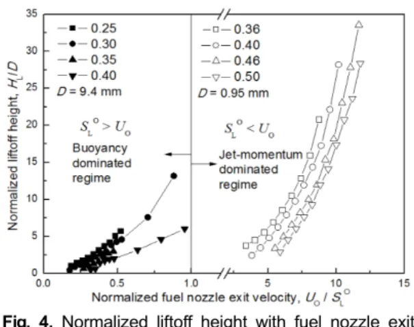
Fig. 4. Normalized liftoff height with fuel nozzle exit velocity considering stoichiometric un-stretched non-adiabatic laminar burning velocity for two different fuel nozzles.
by addition of helium diluent and with increase in the Uo. Direct photographs of lifted flames for Uo = 260 cm/s at various X
F,Oare shown in the Fig. 3(b).
Richardson number Ri, was also evaluated to observe the buoyancy effect and it is in the range of 0.00009
< Ri < 0.0015. Results shows that, buoyancy effect can be suppressed with Uo, and lifted flames were ob- tained at higher Uo than stoichiometric un-stretched non- adiabatic laminar flame speeds. Fig. 4, shows the normalized liftoff height with Uo, considering stoichio- metric un-stretched non-adiabatic laminar burning vel- ocity for two different fuel nozzles 9.4 mm and 0.95 mm. Using 9.4 mm i.d. nozzle co-flow burner lifted flames are obtained at lower Uo than S
Loand for 0.95 mm nozzle diameter lifted flames are obtained at higher Uo than S
Lo. The stoichiometric un-stretched non-adiabatic laminar burning velocities were evaluated by using op- pdif code GRI mechanism. This was because, the evalu- ation with adiabatic flame via Premixed code could not describe the effect of helium addition with high thermal conductivity. This un-stretched non-adiabatic stoichio- metric laminar flame speed was achieved through ex- trapolation of the linear relation of flame speed versus global strain rate in a counterflow configuration. Fig. 4, confirms that lifted flames exists for methane diluted with helium even at high Uo than S
Lo. For such cases, there are some other factors responsible for flame sta- bilization will be discussed later.
Also, change in H
Lwith Uo is shown in Fig. 5(a) for methane diluted with nitrogen (Sc < 1). Direct photo- graphs of lifted flames for Uo = 20 cm/s at different X
F,Ois shown in Fig. 5(b). Even though not shown
Fig. 5. (a) Change in liftoff height with fuel nozzle exit velocity for methane diluted with nitrogen (Sc <
1) at various fuel mole fractions and (b) direct photographs of stationary lifted methane jet flame diluted with nitrogen for Uo = 20 cm/s at (A) X
F,O= 0.32 (B) 0.31 (C) 0.3 (D) 0.29.
clearly flame edge has a tri-brachial structure when H
Lis large, while the nozzle attached flame edge shows that the lean premixed flame wing is merged to the di- ffusion flame. For methane diluted with nitrogen statio- nary lifted flames were observed only in the develop- ing region due to buoyancy effect at low Uo. This was confirmed by evaluating Richardson number Ri [4] at different stoichiometric condition which is in the range of 0.15 < Ri < 32.11. Results shows that, buoyancy effect is more influential at low Uo where Ri number is large but with increase in Uo, Richardson number and buoyancy also decreased, still in this region lifted flames are for- med. Further investigations may require to clarify the reason behind these lifted flames.
3.2. Stabilization of lifted flame