Journal of Institute of Control, Robotics and Systems (2015) 21(2):95-101
http://dx.doi.org/10.5302/J.ICROS.2015.14.9003 ISSN:1976-5622 eISSN:2233-4335
자동 차선 유지 시스템의 전기식 파워 조향 시스템을 위한 슬라이딩 모드 제어기
Sliding Mode Control for an Electric Power Steering System in an Autonomous Lane Keeping System
유 준 영, 김 원 희, 손 영 섭, 정 정 주*
(Jun Young Yu1, Wonhee Kim2, Young Seop Son1,3, and Chung Choo Chung4,*)
1Department of Electrical Engineering, Hanyang University
2Department of Electrical Engineering, Dong-A University
3Global R&D Center, MANDO Corporation
4Division of Electrical and Biomedical Engineering, Hanyang University
Abstract: In this paper, we develop a sliding mode control for steering wheel angle control based on torque overlay in order to resolve the problem of previous methods for Electric Power Steering (EPS) systems in the Lane Keeping System (LKS) of autonomous vehicles. For the controller design, we propose a 2nd order model of the electric power steering system in an autonomous LKS. The desired state model is designed to prevent a rapid change of the steering wheel angle. The sliding mode steering wheel angle controller is developed for the robustness of the disturbance. Since the proposed method is designed based on torque overlay, torque integration with basic functions of the EPS system for the steering wheel angle control is available for the driver’s convenience. The performance of the proposed method was validated via experiments.
Keywords: electric power steering, torque overlay, sliding mode control
NOMENCLATURE qh: Steering wheel angular position [rad]
qr: Reference steering wheel angular position [rad]
qp: Pinion angular position [rad]
qm: Motor angular position [rad]
x : Rack bar position [m] r
i : Current input of the motor [A]
T : Input torque of EPS system (T =K i ) [N·m] t tl: Load torque [N/m]
tp: Pinion torque [N/m]
K : Motor torque constant [N·m/A] t
T : Driver’s torque [N·m] d
T : Friction torque [N·m] f
T : Road reaction torque on the rack and pinion [N·m] r
J : Steering column moment of inertia [Kg·m2] c
B : Steering column viscous damping [N·m/(rad/s)] c
K : Steering column stiffness [N·m/rad] c
M : Mass of the rack [kg] r
B : Viscous damping of the rack [N·m/(rad/s)] r
R : Steering column pinion radius [m] p
K : Tire spring rate [N/m] r
J : Motor moment of inertia [kg·m2] m
B : Motor shaft viscous damping [N·m/(rad/s)] m
N : Motor gear ratio
I. INTRODUCTION
Autonomous vehicles are an important issue to enhance the safety and convenience of the driver in the automotive industry.
Especially, longitudinal control and lateral control are main issues in the view point of vehicle motion control. The longitudinal control is studied for the vehicle following that desires to keep an appropriate headway between the leading vehicle and the controlled vehicle for collision avoidance [1,2]. The aim of the lateral control is to keep the vehicle between lanes [3,4]. Various lateral control methods have been studied for autonomous lane keeping system (LKS) [5-9]. In LKS, the reference steering wheel angle is derived by the lane-keeping control method. Then, the steering wheel angle is controlled by the power steering system.
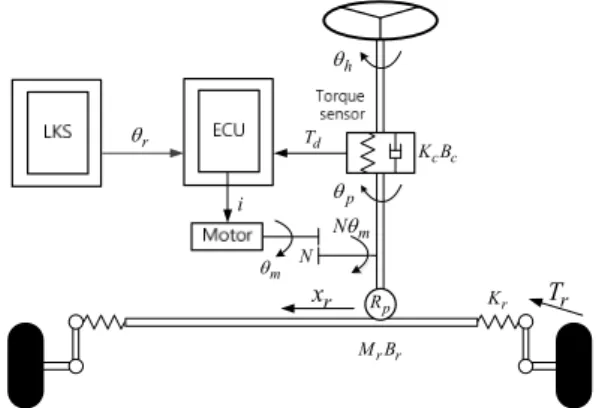
Nowadays electric power steering (EPS) system is substituted for hydraulic power steering (HPS) system, since the EPS system is superior in several aspects including safety, cost, energy efficiency, environmental protection, and assembly compared with the traditional HPS system [3]. The schematic diagram of a column-mounted EPS system is depicted in Fig. 1. The EPS Copyright© ICROS 2015
* Corresponding Author
Manuscript received November 15, 2014 / revised December 15, 2014 / accepted December 30, 2014
유준영: 한양대학교 전자공학과([email protected]) 김원희: 동아대학교 전기공학과([email protected]) 손영섭: 만도([email protected])
정정주: 한양대학교 전기생체공학부([email protected])
※ This work was supported by the Industrial Strategic Technology Development Program (10042808, Development of Driver Assistance Systems Using Camera, Radar and Road Characteristics and 10044620, Automatic Lane Change System for Novice Drivers) funded by the Ministry of Trade, Industry and Energy (MOTIE, Korea).
유 준 영, 김 원 희, 손 영 섭, 정 정 주 96
system consists of a steering wheel, an intermediate shaft, a motor, a torque sensor, a reduction gear, and a rack/pinion structure.
When the driver manually handles the steering wheel, the main role of the EPS system is the torque control of the motor to generate the assistant torque. Various methods for the torque control in EPS have been studied [10-13].
In the LKS of autonomous vehicles, the main role of the EPS system is to make the steering wheel angle track the reference steering wheel angle derived by the lateral control method. The previous lateral control methods regarded the steering wheel angle as the system input [5-9]. These cases may use a DC motor instead of the power steering system or modify the EPS system for the steering wheel angle control. This angle overlay based approach has difficulties and limits since it does not allow the torque combination so that it is difficult to use all of the basic functions of the EPS system Furthermore, it is difficult for driver to smoothly take over the steering wheel control.
On the other hand, in the torque overlay based method, the EPS system can be used for the steering wheel angle control without any modification of the EPS so that a torque integration with basic functions of the EPS is available for the driver’s convenience [14].
Thus, the driver can smoothly take over the steering wheel control from the LKS without uncomfortable feeling [15]. In the torque overlay approach, the steering wheel angle is controlled by the interaction between drivers and EPS system. The torque imposed by the driver is amplified by the basic function of the EPS system.
For the LKS of the autonomous vehicle, the driver’s torque could be affected as disturbance input to the steering wheel angle control and it results in the decrease of the control performance.
The unsymmetrical hysteresis behavior occurred due to the structure and friction of the EPS system is also activated as the disturbance. Furthermore, the EPS model uncertainties make the control become more difficult. Thus the steering wheel angle control method should be designed based on torque overlay with the consideration of both the steering wheel angle tracking and the compensation of the model uncertainty and external disturbance (the steering torque imposed by the driver, the unsymmetrical hysteresis behavior, and the friction so on.)
In this paper, we develop a sliding mode control for steering wheel angle control based on torque overlay in order to resolve the problem of previous methods for EPS in the LKS of the autonomous vehicle. For the controller design, we propose 2nd
order model of the electric power steering system in the autonomous LKS. The desired state model is designed to prevent the rapid change of the steering wheel angle. The sliding mode steering wheel angle controller is developed for the robustness of the disturbance. Since the proposed method is designed based on torque overlay, a torque integration with basic functions of the EPS for the steering wheel angle control is available for the driver’s convenience. The performance of the proposed method was validated via experiments.
II. MATHEMATICAL MODEL OF ELECTRIC POWER STEERING SYSTEM
By applying Newton’s second law, the force and torque balance equations of the steering wheel, the motor, and the shaft are given by [12]
( )
c h c h c h p d
Jq&& +Bq& +K q -q =T (1)
m m m m t l
J q&& +Bq& =K i-t (2)
p
r r r r r r r
p
M x B x K x T
R
+ + =t -
&& & (3)
where qm=Nqp, xr=Rpqp, tp=Kc(qh-qm/N)+Ntl. In the autonomous LKS, the motor of the EPS system directly control the angular position of the steering wheel for the reference angular position tracking without any intention of the driver.
Furthermore, the torque bar is very stiff. Consequently, we can assume that qh»qp. Thus
.
m p h
r p p p h
m
p c h l l
N N
x R R
K N N
N
q q q
q q
t q q t t
= »
= »
æ ö
= ç - ÷+ »
è ø
(4)
From (1)-(4), we obtain
2 1
r p eq t
h h h
eq eq eq eq
K R B K
i d
J N J J J
q&& = - q - q& + + (5)
where
2 r p ,
eq c m h
B B B N B R N q
= + + & eq c m M Rr 2p,
J J J N
= + + N
p .
d r
d T R T
= - N With the definitions of the state and the input as
.
T
h h
x u i
q q
é ù
= ë û
=
&
(6)
Equation (5) becomes
2
0 1 0 0
1 .
t
r p eq
eq eq
eq eq
K
K R B
x x u d
J J
J N J
é ù é ù é ù
ê ú ê ú ê ú
=ê- - ú +ê ú +ê ú
ê ú êë úû êë úû
ë û
& (7)
III. CONTROLLER DESIGN
In the autonomous LKS, the reference steering wheel angle is generated for the lane keeping by the lateral control method [18].
If the lateral offset error at look down (or at look-ahead distance)
qh
Td
qm
K Bc c
i
N
Tr xr
M Br r
Kr Rp
Nqm qr
qp
그림 1. 횡방향 제어를 위한 전기적 파워 조향 시스템의 구조.
Fig. 1. Structure of the electric power steering system for lateral control.
Jun Young Yu, Wonhee Kim, Young Seop Son, and Chung Choo Chung
자동 차선 유지 시스템의 전기식 파워 조향 시스템을 위한 슬라이딩 모드 제어기 97
is large, the steering wheel angle error becomes large. Thus for the fast convergence of the lateral offset error, the steering wheel angle rotates rapidly above the allowed rotation speed. In order to prevent this situation, we design the desired state xd using the reference steering wheel angle θr as
{ {
[{]
1 1
1 2
2 2
1 2
0 1 0
1 0
d d
d d
d d d
d
d d
r r
A x B
d C
x x
k k k
x x
x
y x
é ù é ùé ù é ùq
= +
ê ú ê- - úê ú ê ú
ê ú ë ûê ú ë û
ë û ë û
é ù
= ê ú
ê ú
ë û
&
&
14243
(8)
where k1 and k2 are chosen such that the matrix Ad is Hurwitz., and k is chosen such that r Cd(-Ad)-1Bd=1. The transfer function from θr to yd is
( )1 .
d
d d d
r
Y =C sI-A - B
Q (9)
Generally, the frequency of the steering wheel angle reference generated by LKS is below 0.05 Hz on the curved road of high way. Thus the parameters k1 and k2 are chosen such that the phage lag of (9) is very small below 0.05 Hz. If the steering wheel angle reference includes the high frequency component, the desired state model (8) makes the reference become smooth to prevent that the steering wheel angle rotates rapidly above the allowed rotation speed.
Equation (7) is rewritten as
1 2
2 21 1 22 2 1
x x
x a x a x bu d
=
= + + +
&
& (10)
where
2
21 r p,
eq
a K R
= -J N 22 eq,
eq
a B
= -J t,
eq
b K
=J and 1 1
.
eq
d d
=J For the reference tracking, the control input u is designed as
21 22 1 2
1 2 1 2
1
r
a a k k kr
u x x x x
b b b b bn bq
= - - - - + + (11)
where the sliding mode control law v will be designed later. Now we define the tracking error as
0 0 1 1
1 1 1
2 2 2 .
d
d
d t
e x x d
e x x
e x x
t
= -
= -
= -
ò
(12)
Then the tracking error dynamics are
0 1
1 2
2 1 1 2 2 .
e e
e e
e k e k e v d
=
=
= - - + +
&
&
&
(13)
The sliding surface is designed as
0 0 1 1 2
s s
s=k e +k e +e (14)
where k and s0 k are constant. If s1 s =0, (14) becomes
2 s0 0 s1 1
e = -k e -k e (15)
From (13) and (15),
0 1
1 2
2 s0 0 s1 1.
e e
e e
e k e k e
=
=
= - -
&
& (16)
Thus (16) is simplified as
0 0
0 1
1 1
0 1
.
e
s s
A
e e
k k
e e
é ù
é ù é ù
= ê ú
ê ú - - ê ú
ë û ë ûë û
&
&
1442443
(17)
In (17), ks0 and ks1 should be chosen such that the matrix Ae is Hurwitz. The sliding mode control law v is
eq s
n=n +n (18)
where neq and ns will be designed. We obtain the equivalent control neq to make s& become zero as
( )
( ) ( ) ( )
0 0 1 1 2
0 1 1 2 1 1 2 2
0 1 1 1 2 2 .
s s
s s eq
s s eq
s k e k e e
k e k e k e k e d
k k e k k e d
n n
= + +
= + + - - + +
= - + - + +
& & & &
(19)
From (19),
( 0 1) 1 ( 1 2) 2 .
eq ks k e ks k e
n = - éë - + - ùû (20)
The disturbance d will be compensated for by vs. The disturbance d is d Rp r.
d T T
= - N Thus we can assume that dmax exists such that dmax³ d. In most actual systems, all state variables and external disturbances are physically bounded [16]. For compensation of d, vs is designed as
sgn( )
s ks s
n = - -r (21)
where k >0 and r³dmax. In order to prove the stability, we define the Lyapunov candidate function V [17] as
1 2
2 .
V= s (22)
The derivative of V with respect to time is
( )
( )
0 0 1 1 2
2 2
sgn( ) sgn( )
0
s s
V ss
s k e k e e
s ks s d
ks s s sd
ks s sd
r r r
=
= + +
= - - +
= - - +
= - - + <
& &
& & &
(23)
Thus, s converges to zero. From (11), (20), and (21), the control input is
[ ]
21 1 22 2
1 2
0 1 1 1 2 2
1 [( ) ( ) ] sgn( )
r r
s s
a k a k k
u x x
b b b
k k e k k e ks s
b
q
r
+ +
= - - +
+ - - + - - -
(24) Sliding Mode Control for an Electric Power Steering System in an Autonomous Lane Keeping System
유 준 영, 김 원 희, 손 영 섭, 정 정 주 98
IV. EXPERIMENTAL RESULTS
Experiments were executed to evaluate the performances of the proposed method. The EPS hardware in the loop simulation (HILS) system is shown in Fig. 2. The EPS HILS system consisted of the EPS system, the spring system and the dSPACE.
In this system, the mounted spring was used to emulate the self- alignment torque. DS1501 manufactured by dSPACE Inc. was used as an embedded real-time controller. The control sampling rate was 100 Hz. Since the numerical value of used EPS parameters is proprietary information, it is omitted.
The Bode plot of (9) is from Fig. 3, it is observed that the parameters k and 1 k were chosen such that the phage lag of 2 (9) is very small below 0.05 Hz.
Sinusoidal steering tests were performed to study the characteristics of EPS system. Fig. 4 shows the steering wheel angle response when a sinusoidal command torque, T =3sin
(0.05 2´ pt) was injected artificially. In Fig. 4, the used input torque was amplified fifth times for comparison with the steering wheel angle. Due to the unsymmetrical structure and the friction, the steering wheel angle response was very poor and slow. For the detailed study, four sinusoidal command torques, T =3sin
(0.5 2´ pt), T=3sin(0.1 2´ pt),T=3sin(0.2 2´ pt), and T =
3sin(0.4 2´ pt) were injected artificially. The steering wheel angle responses are shown in Fig. 5. It was observed that the unsymmetrical hysteresis behaviors occurred.
Fig. 6 shows the steering wheel angle tracking performance of the proposed method without the driver’s torque. It is observed that the desired state variable 1
x tracked the reference d x well. r Although the disturbance exists as shown in Figs. 4 and 5, the steering wheel angle also tracked the desired state variable 1
x d
well. The relatively large tracking errors near the zero velocity periods appeared due to the unsymmetrical hysteresis behaviors of EPS system. The high spring force in the experimental set up might be one of the main causes of the relatively large tracking errors near the zero velocity periods. To overcome the unsymmetrical hysteresis behaviors, the control input was also asymmetric as shown in Fig. 6(b). Since the driver’s torque was not injected as the disturbance, the measured driver’s torque was
그림 2. 전기적 파워 조향 시스템의 모의 실험 장치.
Fig. 2. The EPS HILS system.
-80 -60 -40 -20 0 20
Magnitude (dB)
10-2 10-1 100 101 102
-180 -135 -90 -45 0
Phase (deg)
Bode Diagram
Frequency (Hz)
그림 3. (9)의 보드 선도.
Fig. 3. Bode plot of (9).
20 25 30 35 40 45 50 55 60
-30 -20 -10 0 10 20 30
Time [s]
Torque [Nm] / Steering wheel angle [deg]
Torque x 5 Steering wheel angle
그림 4. T=3sin(0.05 2´ pt)를 이용한 조향 테스트: 비교를 위하여 5배 증폭된 토크를 사용함.
Fig. 4. Sinusoidal steering test for T =3sin(0.05 2´ pt): For comparison, the used input torque was amplified five times.
-4 -3 -2 -1 0 1 2 3 4
-40 -30 -20 -10 0 10 20 30 40
Torque [Nm]
Steering wheel angle [deg]
3Nm-0.05Hz 3Nm-0.1Hz 3Nm-0.2Hz 3Nm-0.4Hz
그림 5. T=3sin(0.05 2´ pt), T=3sin(0.1 2´ pt), T =3sin (0.2 2´ pt), 그리고 T=3sin(0.4 2´ pt) 을 이용한 조향 테스트.
Fig. 5. Sinusoidal steering tests for T=3sin(0.05 2´ pt), 3sin(0.1 2 ),
T = ´ pt T =3sin(0.2 2´ pt), and T =3sin (0.4 2´ pt).
자동 차선 유지 시스템의 전기식 파워 조향 시스템을 위한 슬라이딩 모드 제어기 99
almost zero. Fig. 7 shows the steering wheel angle tracking performance of the proposed method with the driver’s torque. In Fig. 7(c), when the driver tried to strongly hold the steering wheel, the measured driver’s absolute torque went up to 3 Nm. To overcome driver’s torque, the input torque also increased. Note that the shaft with torsion bar is nearly rigid in the EPS. Thus, the driver’s torque to hold the steering wheel was activated as torque disturbance as well as angle disturbance in the torque overlay based steering wheel control Consequently, the steering wheel control cannot perfectly be free under the driver’s torque although the driver’s holding torque is compensated for in the torque overlay based steering wheel control. Thus the steering wheel tracking error was relatively larger, however, the performance was recovered after the driver released the steering wheel. It means that if the driver intentionally handles the steering wheel to avoid the emergent situation (i.e., the collision or the malfunction of LKS) then the driver can resist the steering wheel controlled by the EPS so that the driver can relatively smoothly easily take over the steering wheel control compared to the angle overlay based method.
50 55 60 65 70 75 80 85
-20 -10 0 10 20
Time [sec]
Steering Wheel Angle [deg] qr
x1d x1
(a) Steering wheel angle.
50 55 60 65 70 75 80 85
-5 0 5
Time [sec]
Torque [Nm]
(b) Input.
50 55 60 65 70 75 80 85
-5 0 5
Time [sec]
Driver Torque [Nm]
(c) Driver’s torque.
그림 7. 운전자의 토크가 있는 경우의 제시된 방법의 조향각 추종 성능.
Fig. 7. Steering wheel angle tracking performance of the proposed method with the driver’s torque.
V. CONCLUSION
In this paper, we developed the sliding mode control for steering wheel angle control based on torque overlay for the steering wheel angle tracking of EPS in the LKS of the autonomous vehicle. For the controller design, we proposed 2nd order model of the electric power steering system in the autonomous LKS. The desired state model was designed to prevent the rapid change of the steering wheel angle. The sliding mode steering wheel angle controller was developed for the robustness of the disturbance. Since the proposed method was designed based on torque overlay, a torque integration with basic functions of the EPS for the steering wheel angle control is available for the driver’s convenience. The performance of the proposed method was validated via experiments. Although the disturbance exists, the proposed method made the steering wheel angle track the reference well.
REFERENCE
[1] L. Cai, A. B. Rad, and W.-L. Chan, “An intelligent longitudinal controller for application in semiautonomous vehicles,” IEEE
130 135 140 145 150 155 160 165
-20 -10 0 10 20
Time [sec]
Steering Wheel Angle [deg] qr
x1d x1
(a) Steering wheel angle.
130 135 140 145 150 155 160 165
-5 0 5
Time [sec]
Torque [Nm]
(b) Input.
130 135 140 145 150 155 160 165
-5 0 5
Time [sec]
Driver Torque [Nm]
(c) Driver’s torque.
그림 6. 운전자의 토크가 없는 경우의 제시된 방법의 조향각 추종 성능.
Fig. 6. Steering wheel angle tracking performance of the proposed method without the driver’s torque.
유 준 영, 김 원 희, 손 영 섭, 정 정 주 100
Transactions on Industrial Electronics, vol. 57, no. 4, pp. 1487- 1497, 2010.
[2] Y. Chen and J. Wang, “Adaptive vehicle speed control with input injections for longitudinal motion independent road frictional condition estimation,” IEEE Transactions on Vehicular Technology, vol. 60, no. 3, pp. 839-948, 2011.
[3] W. B. Antony, “Innovation drivers for electric power-assisted steering,” IEEE Control Systems Magazine, vol. 23, vol. 6, pp.
30-39, 2003.
[4] J. Navarro, F. Mars, and M. S. Young, “Lateral control assistance in car driving: classification, review and future prospects,” IET Intelligent Transportation Systems, vol. 5, no. 3, pp. 207-220, 2011.
[5] C. J. Taylor, J. KoSeckd, R. Blasi, and J. Malik, “A comparative study of vision-based lateral control strategies for autonomous highway driving,” International Journal of Robotics Research, vol. 18, no. 5, pp. 442-453, 1999.
[6] S. Chaib, M. S. Netto, and S. Mammar, “H∞, adaptive, PID and fuzzy control: a comparison of controllers for vehicle lane keeping,” Proc. of IEEE Intelligent Vehicles Symposium, pp.
139-144, 2004.
[7] E. J. Rossetter and J. C. Gerdes, “Lyapunov based performance guarantees for the potential field lane-keeping assistance system,” ASME Journal of Dynamic Systems, Measurement, and Control, vol. 128, no. 10, pp. 510-522, 2006.
[8] S.-J. Wu, H.-H. Chiang, J.-W. Perng, C.-J. Chen, B.-F. Wu, and T.-T. Lee, “The heterogeneous systems integration design and implementation for lane keeping on a vehicle,” IEEE Transactions on Intelligent Transportation Systems, vol. 9, no. 2, pp. 246-263, 2008.
[9] L. R. K. Talvala, K. Kritayakirana, and J. C. Gerdes, “Pushing the limits: From lanekeeping to autonomous racing,” Annual Reviews in Control, vol. 35, no. 1, 137-148, 2011.
[10] M. Parmar and J. Y. Hung, “A sensorless optimal control system for an automotive electric power assist steering system,” IEEE Transactions on Industrial Electronics, vol. 51, no. 2, pp. 290- 298, 2004.
[11] X. Chen, T. Yang, X. Chen, and K. Zhou, “A generic model- based advanced control of electric power-assisted steering systems,” IEEE Transactions on Control Systems Technology, vol. 16, no. 6, pp. 1289-1300, 2008.
[12] A. Marouf, M. Djemai, C. Sentouh, and P. Pudlo, “A new control strategy of an electric-power-assisted steering system,”
IEEE Transactions on Vehicular Technology, vol. 61, no. 8, pp.
3574-3589, 2012.
[13] S. Sugita and M. Tomizuka, “Cancellation of unnatural reaction torque in variable-gear-ratio,” ASME Journal of Dynamic Systems, Measurement, and Control, vol. 134, no. 2, pp. 021019, 2012.
[14] R. Nicolas, “Torque overlay technology,” [Online]. Available:
http://www.car-engineer.com/torque-overlay-technology/
[15] M. Beecham, “Research analysis: Electric steering creates opportunities for driver assistance,” [Online]. Available:
http://www.justauto.com/analysis/electric-steering-creates- opportunities-for-driverassistanceid107820.aspx
[16] R. L. Kosut, “Design of linear systems with saturating linear control and bounded states,” IEEE Transactions on Automatic Control, vol. 28, no. 1, pp. 121-124, 1983.
[17] H. Khalil, Nonlinear Systems, Upper Saddle River, NJ: Prentice- Hall, 3rd edition, 2002.
[18] Y. S. Son, W. Kim, S.-H. Lee, and C. C. Chung, “Robust multi- rate control scheme with predictive virtual lanes for lane-keeping system of autonomous highway driving,” IEEE Transactions on Vehicular Technology, online published, DOI: 0.1109/TVT.
2014.2356204.
Jun Young Yu
received the B.S in electric electronic engineering from Anyang University, Anyang, Korea, in 2013. He is currently working toward the M.S. degree at the Hanyang University. His main research interests include intelligent vehicle, autonomous driving and robust control.
Wonhee Kim
received the B.S. and M.S. degrees in electrical computer engineering, and Ph.D.
degree in electrical engineering from Hanyang University, Seoul, Korea, in 2003, 2005, and 2012, respectively. Dr.
Kim is an assistant professor of the Department of Electrical Engineering, Dong-A University. From 2005 to 2007, he was with Samsung Electronics Co., Korea. In 2012, he was with the Power &
Industrial Systems R&D Center of Hyosung Co., Korea. In 2013, Dr. Kim was a post doctoral researcher of the Institute of Nano Science & Technology, Hanyang University and was also a visiting scholar of the Department of Mechanical Engineering, University of California, Berkeley. His current research interests include nonlinear control, nonlinear observer, and their industrial applications.
Young Seop Son
received the B.S. and M.S. degrees in electronics engineering from Sogang University, Seoul, Korea, in 1997, 1999, respectively. He is currently working toward the Ph.D. degree at the Hanyang University. Since 1999, he is working in Global R&D Center, Mando Co. His main research interests include intelligent vehicle, autonomous driving and robust control. Mr. Son is a member of the Korea Society of Automotive Engineers, the Institute of Control, Robotics and Systems, and the Korean Institute of Electrical Engineers.
Chung Choo Chung
received the B.S. and M.S. degrees in electrical engineering from Seoul National University, Seoul, Korea, and the Ph.D.
degree in electrical and computer engineering from the University of Southern California, Los Angeles, in 1993.
From 1994 to 1997, he was with Samsung Advanced Institute of Technology, Korea. In 1997, he joined the Jun Young Yu, Wonhee Kim, Young Seop Son, and Chung Choo Chung
자동 차선 유지 시스템의 전기식 파워 조향 시스템을 위한 슬라이딩 모드 제어기 101
faculty of Hanyang University, Seoul, Korea. Dr. Chung was an Associate Editor for the Asian Journal of Control (AJC) from 2000 to 2002 and an Editor for the International Journal of Control, Automation and Systems (IJCAS) from 2003 to 2005.
He was an Associate Editor for the 2003 IEEE Conference on Decision and Control (IEEE CDC), and an Associate Editor and the Co-Chair of Publicity of the International Federation of Automatic Control (IFAC) World Congress, Korea in 2008. He served as a program committee member of the American Society of Mechanical Engineers (ASME) International Conference on Information Storage and Processing Systems (ISPS) 2011. He was a guest editor for the special issue on advanced servo control for emerging data storage systems published by IEEE Trans. on Control System Technologies (TCST). Currently he is an Associate Editor of TCST and also a Program Co-Chair of 2015 IEEE Intelligent Vehicles Symposium.
Sliding Mode Control for an Electric Power Steering System in an Autonomous Lane Keeping System