CFD Study Analysis on the Steam Ejector with Varying Turbulence models
Supriyanto Wibowo1, Tony Utomo2, HanSik Chung3, and HyoMin Jeong3
1Mechanical and Precision Engineering Department, Gyeongsang National University, Tongyeong 650-160, Korea
2Mechanical Engineering Department, Engineering Faculty, Diponegoro University, Semarang, Indonesia
3School of Mechanical and Aerospace Engineering, The Institute of Marine Industry, Gyeongsang National University, Tongyeong 650-160, Korea
ABSTRACT: CFD analysis has been carried out in this paper. The purpose is to reveal the understanding of flow phenomena inside the ejector on the performance of steam ejector using three well known turbulence models. In this study, the ejector design was modeled using finite area CFD techniques to resolve the flow dynamics in the ejectors. Furthermore, from this study it can be concluded that by employed vary of turbulence models there are different results in pressure distribution, in contour of Mach number and in Entrainment ratio inside the steam ejector.
Key words: CFD analysis, turbulence model,steam ejector.
Nomenclatur
k turbulent kinetic energy (m2/s2) M Mach number
mass flow rate (kg/s) P pressure (Pa)
S modulus of the mean rate-of-strain stress tensor (1/s)
Gk generation of turbulent kinetic energy due to the mean velocity gradients
Gb generation of turbulent kinetic energy due to buoyancy
YM contribution of the fluctuating dilatation in compressible turbulence
Greek letters
ρ density (kg/m3)
εϕεχτορ εφφιχιενχψ μ viscosity (kg/m.s)
ε dissipation of turbulent kinetic energy (m2/s2)
1. Introduction
The ejector was invented by Sir Charles Persons around 1901 for removing air from a steam engine’s condenser. Ejectors are simple pieces of equipment. Nevertheless, many of their possible services are overlooked. They often are used to pump gases and vapors from a system to create a vacuum. However, they can be used for a great number of other pumping situations. Ejectors are employed in the industry in numerous, unique and
08-W-098
대한설비공학회 2008 동계학술발표대회 논문집 pp. 572 ~ 577
even sometimes bizarre ways. They can be used singly or in stages to create a wide range of vacuum conditions, or they can be operated as transfer and mixing pumps. The ejectors have advantages over other kinds of pumps such as;
rugged and simple construction, capability of handling enormous volumes of gases in relatively small sizes of equipment, less maintenance requirements, simple operation.
Aiming at their practical use, numerous studies in the early stage of development have generally concentrated on relating the geometrical factors of the ejector to its performance. To an end of cutting its immense budget for full-scale ejector test, the computer methods support cost efficient development. For two decades, computational fluid dynamics (CFD) have been extensively used for visualizing the internal flows and shock structures in supersonic ejectors, however, these studies have generally focused on revealing flow structure at steady operation and a few of them even excluded the turbulence compressibility effects or turbulence itself. Correspondingly, the validation and application of the methods were attempted for the overall steady-performance parameters of the supersonic ejectors. However, due to the lack of description on the spatially and temporally instant flow parameters, these static approaches may not be exactly becoming on filling their role of performance prediction. Nevertheless, recent CFD studies by such asSankaran et al. (2002), Desevaux and Lanzetta (2004) have demonstrated that CFD could be an effective diagnostic tool for analysis, design, and performance optimization of the supersonic ejectors. Desevaux and Lanzetta (2004) also validated their numerical results with measured static pressures along the centerline and non-dimensional pseudo-shock lengths in diffuser-unstarting mode.
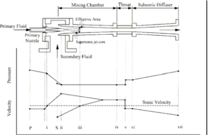
A schematic view of the typical steam ejector is shown in Fig 1. Ejector generally allows performingthe mixing and/or the recompression of two fluid streams. The fluid with the highest total energy is the motive or primary stream (P), while the other, with the lowest total energy (S) is the secondary or the induced stream. Operation of ejector is the motive stream (high pressure and temperature) expands and accelerates through the primary nozzle (i), it fans out with supersonic speed to create a very low pressure region at the nozzle exit plane (ii) and subsequently in the mixing chamber. According to the differences pressure of two positions, by an entrainment-induced effect, the secondary stream is drawn into mixing chamber. The primary fluid’s expanded wave was thought to flow and form a converging duct without mixing with the secondary fluid. At some cross-section along this duct, the speed of secondary fluid is rises to sonic value (iii) and chokes. This cross-section was defined by Munday and Bagster (1977) as the ‘effective area’.
The mixing process begins after the secondary flow chokes. This mixing causes the primary flow to be retarded while secondary flow is accelerated. By the end of the mixing chamber, two streams are completely mixed and the static pressurewas assumed to remain constant until it reaches the throat section (iv). The pressure in the mixing chamber was a function of primary fluid, secondary fluid, and the back pressure of ejector (Zeren, F.
1982). Due to a high-pressure region downstream of the mixing chamber’s throat, a normal shock of essential zero thickness is induced (v). This shock causes a major compression effect and a sudden drop in the flow speed from supersonic to subsonic.
A further compression of the flow is achieved (vi) as it is brought to stagnation through a subsonic diffuser.
Property Model
Density Ideal Gas Model
Cp (Specific Heat) 2170 J/kgK Conductivity 0.0276 W/mK Viscosity 1.31619 x 10⁻⁵ kg/ms Molecular Weight 18.01 kg/kgmol Fig.1. Schematic view of ejector and variation of
pressure and velocity along the ejector.
The high speed flow and the extensive mixing process that take place in ejectors, make the flow highly turbulent. Therefore, accurate modeling of the flow will require the use of a proven turbulence model. In this research, 3 different turbulence models, namely standard k-epsilon, realizable k-epsilon, and RNG k-epsilon have been tested and compared.
2. Computational Fluid Dynamics Modeling The problem under investigation here involved the supersonic flow inside the flow passage of steam ejector. In order to simulate this particular situation, Gambit and FLUENT were used as grid generator and the CFD solver, respectively. Gambit was used to create the calculation domain and grid elements of the model. The mesh and model was created in a two dimension (2-D) domain. However, the axisymetric solver was applied and therefore, the three dimensional effect (3-D) was taken into account in the simulation. The mesh was made of about 24,000 structured quadrilateral elements, as shown in Fig.2. The turbulence models employed were standard k epsilon, realizable k epsilon, RNG k epsilon with high Reynolds number.
All the walls in the ejector (i.e. nozzle, mixing chamber, mixing tube, and diffuser walls) are mmmm
approximated as impermeable adiabatic walls. This assumption is common in steam ejector application and is based on the fact that heat transferper unit mass is low given the typical high flow capacity of an ejector.
Primary and secondary inlets are modeled as pressure inlets. This boundary condition means that the total pressure at these ports will be the primary input, as opposed to other options such as mass flow rate or velocity. Temperature will also be needed at these ports for calculations pertaining to the energy equation.
Ejector exit is modeled as a pressure outlet. In this case, only the pressure value is needed while the temperature is calculated using the energy equation.
Fig.2.Calculation domain and grid structure of the ejector CFD model.
Physical properties of the working fluids were steam for both primary and secondary stream at the ejector. Table 1summarize the physical model of those working fluids.
Table 1. Properties and Models of Saturated steam
2.1. Turbulent Modeling
2.1.1. The standard k- ε model
The transport equation for k and εafter modeling may be expressed as:
(1) and
(2)
2.1.1. The RNG k-ε model
The RNG-based k-ε turbulence model is derived from the instantaneous Navier-Stokes equations, using a mathematical technique called
``renormalization group'' (RNG) methods. The analytical derivation results in a model with constants different from those in the standard k-ε model, and additional terms and functions in the transport equations for k and ε.
Transport Equations for the RNG k-ε Model has a similar form to the standard k-ε model:
(3) and
(4) 2.1.2. The realizable k- ε model
The term ``realizable'' means that the model satisfies certain mathematical constraints on the normal stresses, consistent with the physics of turbulent flows.
The modeled transport equations for k and ε in the realizable k- ε model are:
(5) and
(6) where
(7)
and
(8)
3. Results and Discussion
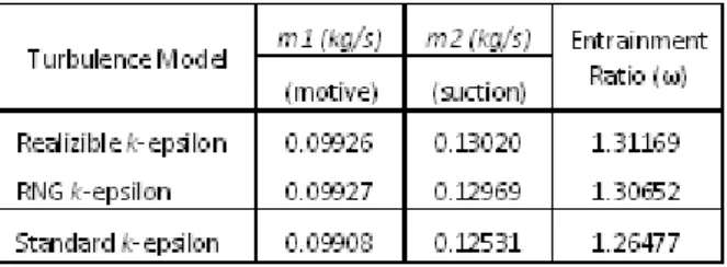
Table 2shows the comparison of entrainment ratio between experimental and CFD results for various suction and discharge pressures at a fixed motive pressure. It is seen that the highest entrainment ratio obtained in realizable k-epsilon model and the lowest entrainment ratio obtained in standard k-epsilon model.
Table 2. Comparison of entrainment ratio between different turbulent models.
Fig. 3 and fig. 4 illustrates the static pressure and velocity magnitude distribution on the centerline of base ejector. The distributions were taken at operating condition where P1 (motive), P2 (suction) and P3 (dischard) at 2.66, 0.19 and 0.25 barsabsolute respectively. From this figure, it can be seen that a series of shock waves occur inside the mixing tube, starting from converging to constant area mixing tube. The region where the series of shocks occurs is known as a shock train region.
These shock waves consist of normal and/or oblique shock and involving a pressure rise.
Fig.3. Static pressure distribution along the centerline of the ejector.
Fig.4. Velocity magnitude distribution along the centerline of the ejector.
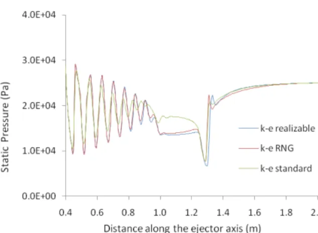
Fig.5 represents the influence of turbulence model on the pressure distribution along the centerline of the ejector, plotted from the primary nozzle outlet to the diffuser outlet. Every turbulence model has different static pressure inside of mixing duct. However, the outlet pressure of diffuser is remains the same. In this condition, the motive suction and discharge pressures are the same as the operating condition of base ejector.
Fig.5. Static pressure distribution in steam ejector with various turbulence models
Fig. 6 illustrates the contour of Mach number and shock waves phenomena inside the converging duct to mixing tube in different turbulence models.
It is seen that the length of shock train region is vary with different turbulence models. In this research, the shortest is standard k- epsilon, and for realizable k-epsilon and RNG k-epsilon is almost same.
standard k-epsilon realizable k-epsilon
RNG k-epsilon
Fig.6. Contour of Mach number for various turbulence models.
4. Conclusion
The CFD analysis was performed for the supersonic flow in the constant-pressure mixing ejector. The simulation has been shown the phenomena inside the ejector, otherwise it is difficult in experimental. Vary in employed turbulence model got also vary result.
Finally, from this investigation, it can be concluded that CFD analysis can give a good complement to the experimental approach.
Acknowledgement
The authors gratefully acknowledge the financial support provided by Korea Heat and Fluid Technology, Engineering Research Institute of Gyeongsang National University.
References
1. Sankaran, S., Satyanarayana, T.V.V., Annamalai, K., Visvanathan, K., Babu, V,. Sundararajan, T., 2002. CFD analysis for simulated altitude testing of rocket motors. Canadian Aeronautics and Space Journal 48 (2), 153-162
2. Desevaux, P., Lanzetta, F., 2004. Computational fluin dynamic modeling of pseudoshock inside a zero-secondary flow ejector. AIAA Journal 42, 1480-1483.
3. Munday, J.T. and Bagster, D.F. 1977. A new theory applied to steam refrigeration. Ind Eng Chem Process Des Dev 16(4): 442-449
4. Zeren, F. 1982. Freon-12 vapor compression jet pump solar cooling system. PhD thesis, Texas A&M University.