- 기호설명 -
A : 노즐 오리피스 면적 (mm2)
Cd : 유출계수
D : 노즐 오리피스 직경 (mm)
Q : 분사 유량 (m3/s) P : 압력 (N/m2)
V : 분사 유속 (m/s)
ρ : 밀도 (kg/m3) μ : 점성 (N·s/m3)
σ : 캐비테이션 수
Dhy : 수력 직경 (mm) Pa : 대기 압력 (bar) Pv : 증기 압력 (bar) Pn : 노즐내부 압력 (bar)
E(k) : 타원 이종적분
1. 서 론
.
, 학술논문
< > DOI:10.3795/KSME-B.2010.34.10.933 ISSN 1226-4881
노즐 오리피스 형상에 따른 Discharge Coefficient 와 에 관한 실험적 연구
Cavitation
김성열
*구건우
*홍정구
**이충원
*경북대학교 기계공학부 경북대학교 기계연구소
* , **
Experimental Study of Discharge Coefficient and Cavitation for Different Nozzle Geometries
Sung Ryoul Kim
*, Kun Woo Ku
*, Jung Goo Hong
**and Choong Won Lee
** Dept. of Mechanical Engineering, Kyungpook Nat’l Univ.,
** Institute of Mechanical Engineering Technology, Kyungpook Nat’l Univ.
(Received July 1, 2010 ; Revised July 31, 2010 ; Accepted August 2, 2010)
Key Words: Elliptical Nozzle(타원형 노즐), Nozzle Cavitation(노즐 캐비테이션), Discharge Coefficient(유출 계수), Cavitation Number(캐비테이션 수)
초록: 본 연구는 타원형 노즐과 원형 노즐 내부에서 발생되는cavitation의 발생 및 성장을 실험적으로 관찰하였다.
원형 노즐과 타원형 노즐의 cavitation 특성을 가시화 하기위해 투명한 아크릴로 노즐을 제작하였다 실험에 사용.
된 노즐들은 같은 단면적으로 제작되었으며 타원형 노즐의 경우 형상비, (a/b)를 다르게 하였다 분사압력의 증가에.
따라 노즐내부 유동은 no cavitation, cavitation, hydraulic flip 영역으로 나뉘어졌다 노즐의 형상에 상관없이. no
과 영역에서는 분사압력의 증가에 따라 유량은 증가하며 유출계수는 감소하는 경향을 나타냈
cavitation cavitation ,
다 그러나. hydraulic flip 영역에서의 유량계수는 일정한 값을 나타냈다 타원형 노즐은 원형 노즐에 비해 높은.
에서 이 성장 발달하였다 특히 타원형 노즐에서는 장축의 가 단축보다
cavitation number cavitation , . cavitation length
길게 나타났다.
Abstract: The purpose of this study is to investigate the generation and development of cavitation in circular and elliptical nozzles. In order to investigate the influence of cavitation, the experiment was conducted with a set of elliptical nozzles that had the same cross-sectional area, different orifice aspect ratios (a/b). Each nozzle was made of acrylic so that visualization was possible. With the injection pressure, the internal flow of the nozzle was classified into the no-cavitation, cavitation, and hydraulic-flip regions. Regardless of the nozzle geometry, with the injection pressure, the flow rate in the no-cavitation and cavitation regions increased and the discharge coefficient decreased. However, the flow rate was constant in the hydraulic-flip region. In the elliptical nozzles, the generation and development of cavitation occurred at higher cavitation number than that in the case of a circular nozzle.
Corresponding Author, [email protected] 2010 The Korean Society of Mechanical Engineers
Ⓒ
. CO2
. PM
NOx .
.
cavitation
.(1,2) Sou (3) 2-D
cavitation
. cavitation
4 , cavitation
super cavitation cavitation
. Stainly Cameron (4) cavitation , super cavitation cavitation Turbulent Kinetic Energy(TKE)
. K. Rananurith(5) (l/d)
(Cd)
,
5 Reynolds
number
, cavitation
. Park (6)
cavitation
cavitation
. cavitation
. ,
. Gong Yunyi (7)
,
Axis switching
, SMD
,
. T. V. Kayap (8) Axis switching
. Axis switching
,
.
.
cavitation
, cavitation
. (a/b)
. cavitation
. Re , cavitation
.
실험 장치 및 방법 2.
실험 장치 2.1
cavitation ·
Fig. 1
Fig. 1 Experimental setup
Table 1 Geometrical details for the orifices
(a) Elliptical nozzle (b) Cylindrical nozzle Fig. 2 Schematics of test nozzle, (a)Elliptical nozzle
(b)Cylindrical nozzle
.
, .
. (N2) .
,
.
pressure transducer ,
(Koreameter,
KTM-800) .
Data acquisition board
. cavitation
(drelloscop 3020) CCD camera(vieworks, VM-2M 35) , CCD camera image grabber
.
cavitation Fig. 2
Table 2 Experimental condition
Working Fluid Water
Injection Pressure 0.5 ~ 5.0 bar
Property of Fluid
Temperature (°C) 20
Density (kg/m3) 998.25 Dynamic Viscosity (N·s/m2) 1.002*10-3 Surface Tension (N/m) 7.28*10-2 Vapor Pressure (N/m2) 2.338*103 Cavitation Number 1.77 ~ 0.95
Ambient Pressure 1.01325 bar
. 3mm
,
(a/b) 1.5, 2, 3 . Table 1
specification .
(l/d) 4 .
실험 방법 2.2
cavitation
.
Table 2 .
, ·
.
cavitation number( ), Reσ ,
(Cd) ,
, .
.
(V) (Q=AV)
,
(1)
∙
(2)
∆
(3)
(4)
sin (5)
Circumference of ellipse=2a E(k)∙
Nozzle Type Major Axis, a
(mm)
Minor Axis, b
(mm)
Hydraulic Diameter, Dhy(mm)
Aspect Ratio, a/b
Area, A (mm2) Cylindrical
(C) 3.007 3.007 3.007 1 7.098
Elliptical 1.5
(E1.5) 3.702 2.464 2.927 1.54 7.161
Elliptical 2
(E2) 4.242 2.139 2.768 2.01 7.123
Elliptical 3
(E3) 5.182 1.818 2.543 2.94 7.395
Re (Dhy)
. ΔP , p wetted
perimeter .
matlab
. 100Hz
15 .
실험 결과 및 고찰 3.
분사 압력 변화에 따른 유동특성 3.1
cavitation (No cavitation) cavitation
(Cavitation), cavitation
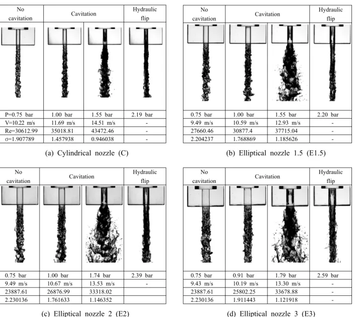
(Hydraulic flip) . Fig. 3
cavitation .
cavitation ,
cavitation , .
cavitation
, E2 E3
No
cavitation Cavitation Hydraulic
flip
P=0.75 bar 1.00 bar 1.55 bar 2.19 bar V=10.22 m/s 11.69 m/s 14.51 m/s -
Re=30612.99 35018.81 43472.46 -
=1.907789
σ 1.457938 0.946038 -
No
cavitation Cavitation Hydraulic
flip
0.75 bar 1.00 bar 1.55 bar 2.20 bar
9.49 m/s 10.59 m/s 12.93 m/s -
27660.46 30877.4 37715.04 -
2.204237 1.768869 1.185626 -
(a) Cylindrical nozzle (C) (b) Elliptical nozzle 1.5 (E1.5)
No
cavitation Cavitation Hydraulic
flip
0.75 bar 1.00 bar 1.74 bar 2.39 bar
9.49 m/s 10.67 m/s 13.53 m/s -
23887.61 26876.99 33318.02 2.230136 1.761633 1.146352
No
cavitation Cavitation Hydraulic
flip
0.75 bar 0.91 bar 1.79 bar 2.59 bar
9.43 m/s 10.19 m/s 13.30 m/s -
23887.61 25802.25 33678.88 -
2.230136 1.911443 1.121918 -
(c) Elliptical nozzle 2 (E2) (d) Elliptical nozzle 3 (E3)
Fig. 3 Cavitation region in different injection pressure, (a)Cylindrical nozzle (b)Elliptical nozzle 1.5 (c)Elliptical nozzle 2 (d)Elliptical nozzle 3
. cavitation .
hydraulic flip .
Fig. 4 .
Cavitation
. cavitation hydraulic flip
cavitation .
cavitation
. Fig. 5
. No cavitation
cavitation
, hydraulic flip
Fig. 4 The relationship between pressure in nozzle and flow rate
Fig. 5 The relationship between pressure in nozzle and discharge coefficient
.
, E1.5, E2
, E3 .
,
.
3.2 Reynolds number에 대한 discharge coefficient
Fig. 6 Re .
cavitation Re
.
Re .
Re cavitation
Re cavitation . E1.5 E2 Re
.
Re hydraulic flip
, hydraulic flip
Re .
Re cavitation cavitation
. 3.3 Cavitation number에 따른 cavitation length
SATO( 9 ) separated
vortex cavitation
, cavitation (main cavitation)
, cavitation cloud shedding
Fig. 6 The relationship between Reynolds number and discharge coefficient
Fig. 7 Cavitation length in elliptical nozzle (mm)
(a) Major axis
(b) Minor axis
Fig. 8 The relationship between cavitation number and cavitation length, (a)Major axis (b)Minor axis
.
cavitation shedding
cavitation length .
cavitation
cavitation length
. Fig. 7 cavitation length
. cavitation length
.
Fig. 8 cavitation number cavitation length . cavitation number
cavitation length .
cavitation number
cavitation .
cavitation
,
.
,
(10).
cavitation .
(streamline)
, cavitation number
cavitation .
1.5bar
cavitation length ,
. E1.5
cavitation number cavitation .
cavitation number
cavitation length .
streamline
.
4. 결 론
cavitation . .
(1) ,
,
. hydraulic flip
. cavitation
No cavitation, cavitation, hydraulic flip .
(2) Re
cavitation , Re
.
(3) cavitation
, cavitation . 1.5bar cavitation
.
후 기
2010 ( )
.(2010-0020089)
참고문헌
(1) Lee, S. Y., 1996, Liquid Atomization, Minumsa, korea, pp.165~278.
(2) Lefebvre, A. H., 1989, Atomization and Spray, Hemisphere Publishing Corporation, USA, pp.201~307.
(3) Sou, A., Hosokawa, S. and Tomiyama, A., 2007,
"Effects of Cavitation in a Nozzle on Liquid Jet Atomization," International journal of Heat and Mass Transfer, Vol. 50, lss. 17-18, pp. 3575~3582.
(4) Stanley, C., Rosengarten, G., Milton, B. and Barber, T., 2008, "Investigation of Cavitation in a Large-Scale Transparent Nozzle," FISITA 2008
Student Congress, F2008-SC-001.
(5) Ramamurthi, K. and Nandakumar, K., 1999,
"Characteristics of Flow Through Small Sharp-Edged Cylindrical Orifices," Flow Measurement and Instru- mentation 10, pp. 133~143.
(6) Park, S. H., Suh, H. K. and Lee, C. S., 2007,
“Effects of Nozzle Orifice Shape and Nozzle Length-to-Diameter Ratio on Internal and External Flow Characteristics of Diesel and Biodiesel Fuel,”
Trans. of the KSME(B), Vol. 31, No. 3, pp. 264~272.
(7) Gong, Y., Liu, C., Huang, Y. and Peng, Z., 1998,
“An Experimental Study on Droplet Size Character- istics and Air Entrainment of Elliptic Sprays,” SAE technical paper series, 982545.
(8) Kasyap, T. V., Sivakumar, D. and Raghunandan, B.N., 2009, "Flow and Breakup Characteristics of Elliptical Liquid Jets," International journal of Multiphase Flow, V. 35, pp. 8~19.
(9) Sato, K. and Saito, Y., 2002, "Unstable Cavitation Behavior in a Circular Cylindrical Orifice Flow,"
JSME International Journal Series B, Vol.45, No.3, pp. 638~645.
(10) Potter, M. C. and Wiggert, D. C., 2002, Mechanics of Fluid, BROOKS/COLE, USA, pp.106~116.