경사 전극 배열을 이용한 각도방향 마이크로 구동부 제작
최 석 문
1)
․박 성 준2)
삼성전기 중앙연구소
1)
․충주대학교 기계공학과*,2)
Skewed Electrode Array(SEA) and Its Application as an Angular Microactuator
Seok-Moon Choi
1) ․
Sung-Jun Park2)
1)R&D Center, Samsung Electro-Mechanics, Suwon, Korea
2)Department of Mechanical Engineering, Chungju National University, Chungju, Korea (2011.08.13 Received / 2011.09.21 Accepted)
Abstract : The angular electrostatic microactuator using skewed electrode array (SEA) scheme was proposed. The moving and fixed electrodes are arranged to make the driving force perpendicular to the rotating moment of arm. By changing the electrode overlap length, the magnitude of electrostatic force and stable displacement will be changed. In order to optimize the design, electrostatic FE analysis were carried out and the empirical force model was established for SEA. Simulation was performed to make the comparison between conventional actuators and SEA. The proposed SEA generates actuating torque 2 times greater than a comb-drive and stable actuator displacement 40% greater than a parallel plate type actuator. The angular electrostatic microactuator using skewed SEA scheme was designed and fabricated using SoG process.
Key words : Skewed Electrode Array ( 경사 전극 배열), Microactuator (미소구동부), Hard Disk Drive (하드디스크)
3) 1. Introduction
Microactuators are one of the most important components of microsystems. The actuation forces generated in microactuators are based on piezoelectric, electromagnetic and electrostatic principles. In recent years, electrostatic actuation, the conversion of electrostatic energy into mechanical motion, is the most widely used in MEMS-based microactuators. It has a several advantages over electromagnetic or piezoelectric actuation. The structural material only needs to be conductive, rather than ferromagnetic of
*
Corresponding author. E-mail: [email protected]
piezoelectric, so it is relatively easy to fabricate the electrostatic microactuator. It does not have the mechanical components such as magnetic cores and metal coils found in an electromagnetic actuator, so it generates higher force or torque output per unit volume than electromagnetic actuation. The actuator displacement can be measured using capacitive position sensing electrodes and the response is very fast so it is capable of high-bandwidth operation.
The design for an electrostatic microactuator have been of two distinct types, comb-drive and parallel plate configurations as shown in figure 1 (a), (b). The difference between these types lies only in the direction of the moving electrode.
(a) Comb-drive
(b) Parallel plate
(c) Skewed Electrodes Array
Fig. 1 Electrode configuration of conventional and SEA electrostatic actuators
The parallel plate configuration generates electrostatic force an order of magnitude greater than comb-drive but it has pull-in instability and non-linearity characteristics. In this paper, a new driving scheme of electrostatic actuation that generate actuating torque 2 times greater than the comb-drive and stable actuator displacement 40% greater than the parallel plate was proposed. The moving and stationary electrodes are arranged to make the driving force perpendicular to the rotating moment of arm as shown in figure 1 (c). The empirical force model including fringe field effects was established for the proposed type (SEA) through electrostatic FE analysis. The angular electrostatic microactuator using skewed SEA scheme was designed and fabricated using SoG process
2. Design
2.1 Conventional Electrostatic Actuators
There are two common types of electrodes configuration, comb-drive and parallel plate, in conventional electrostatic actuation. As shown in figure 1 these electrode types differ only in the direction of the movable electrode. The electrostatic force generated between the fixed electrode and the moving electrode is given by
(1)where C(x) denotes the capacitance between the fixed electrode and the moving electrode as a function of the movable electrode displacement x and the electrodes configuration.
2.1.1 Parallel Plate Actuators
Neglecting fringing field effects, which means the overlap electrode length(
) is much larger than the electrode width(W) and the capacitive gap(g) between fixed electrode and moving electrode(g), the capacitance between a pair of parallel plate electrodes is given byFixed Electrode
Moving Electrode
F
xF
yg
L l
pDriving direction W
L W
y x
F
ef
(2)
Where,
is the permittivity of air, h and
are the height and overlap length of electrode respectively.Substitution of (2) into (1) yields an electrostatic force between a pair of parallel plate electrodes
(3)Note that electrostatic force of parallel plate shows an inverse-square-law dependence on moving electrode displacement x. .
2.1.2 Comb-drive Actuators
As long as the movable electrode displacement is less than the overlap electrode length, the capacitance between a pair of comb-drive electrodes is given by
(4)
Substitution of (4) into (1) yields an electrostatic force between a pair of comb-drive electrodes
(5)Note that the comb-drive electrostatic force is independent of moving electrode displacement while the parallel plate is function of the x. Since the electrode length is 10 to 20 times greater than the capacitive gap between electrodes, the parallel plate electrostatic force is much larger than comb-drive but comb-drive can provide a long stroke and generate constant force along the stroke.
2.2 Skewed Electrodes Array
Analysis model of Skewed Electrode Array for angular actuation scheme is shown in figure 2. The
moving and fixed electrode are arranged to make the driving force perpendicular to the rotating moment of arm as shown in Figure 1 (c).
Fig. 2 Electrode configuration of SEA model
The electrostatic force between the movable and fixed electrode,
, can be divided into two force component and
as shown in figure 2. By changing the electrode overlap length, the electrostatic force and skew angle will be changed.
tan
(6)
2.2.1 Electrostatic force model
Generally, the ratio of overlap electrode length to width,
, in commonly used electrostatic actuators such as comb-drive, parallel plate is large enough to neglect fringing field effects. In the SEA, the ratio of
is less than 5, so the fringe field effect will be occur which will change electrostatic force component the
and the
illustrated in figure 2. It is very difficult to calculate electrostatic force Fe including fringe field effects analytically. In order to estimate this effects, electrostatic force Fe decomposed into force component
and
and FE analysis using the Maxwell software were carried out for the capacitor model in figure 2 with the following condition : driving voltage =10 V,
,
2.2.1.1 Approximation of electrostatic force component F
xFigure 3 shows the calculated electrostatic forces component
per unit height of FE models and comb-drive. The comb-drive force per unit height neglecting fringe field effects was determined using equation (4). Due to the influence of fringe fields, the force
component on the SEA model was slightly lower than comb-drive force less than
and the difference increases with increasing
. As shown in figure 3,
can be determined as follows for less than
.
×
(7)where, is the permittivity of air, g is the capacitive gap between moving and fixed electrode, V is the input voltage and is the correction factor of
for fringe fields which depends on the electrode configuration.Fig. 3 F
xaccording to overlap
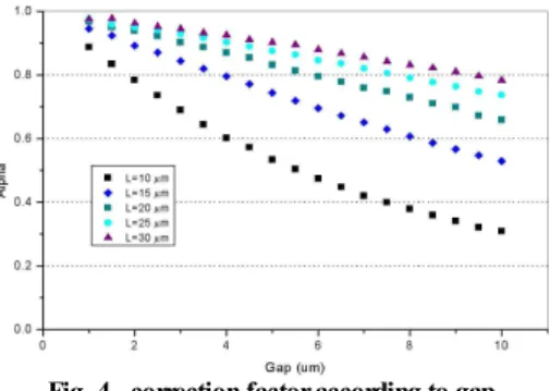
In order to determine the correction factor alpha, alpha-gap characteristics of SEA are calculated as illustrated in Figure 4. The correction factor alpha decreases linearly with increasing gap, so it can be denoted as the following equation.
× (8)where, g is the capacitive gap between electrodes, A is function of the electrode length L.
Fig. 4 correction factor according to gap
For determination the slope of correction factor .
characteristics have been calculated. As illustrated in figure5, 3-rd order polynomial curve fitted line shows good agreement with FEM results.
(9)Fig. 5 Slope of alpha according to electrode length
2.2.1.2 Approximation of electrostatic force component F
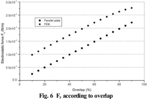
yThe contribution of the fringe field effects to the force component
was investigated for the SEA model. Figure 6 shows the calculated electrostatic forces
per unit height of FE models and parallel plate. The parallel plate force neglecting fringe field effects was determined using equation (5). Due to the influence of fringe fields, the force
on the SEA model was higher than parallel plate force. As illustrated in figure 6, the force difference between parallel plate model and FEM is constant with increasing overlap length so
can be expressed as the following equation.
(10)where, is correction factor of
for fringe fields which depends on the electrode configuration.Fig. 6 F
yaccording to overlap
To obtain the influence of fringe field effects on
, -gap characteristics at various electrode length and width are investigated. As shown in figure 7, beta decreases with increasing gap and for a given gap the value of beta is constant at various electrode length and width. Consequently, can be denoted as the following equation.
(11)
where, is the curve fitted value by considering gap and driving displacement.
Fig. 7 Beta according to gap
2.2.2 Evaluation of the approximate force model
Simulation was performed to make the comparison between the approximative model and FE model on the SEA in figure 2. The capacitive electrodes specs are in Table 1. For a given design specification, the electrostatic force components in each direction can be determined.
×
(12)
(13)Table 1 Electrodes specification of SEA
Parameters Symbol Value Length of stationary electrode Ls 20 μm Length of moving electrode Lm 20 μm Width of stationary electrode Ws 20 μm Width of moving electrodes Wm 6 μm Initial gap between electrodes g 6 μm Overlap length lp 6 μm Driving voltage V 18 volt
Figure 8 illustrates the electrostatic force according to moving electrode displacement. For the investigated stroke range less than one-third of the initial gap(2m), the approximate model of SEA shows a good agreement with FE-model including fringe fields effect within an accuracy of 5% .
Fig. 8 Comparison between FEM and approximative model
Electrostatic force according to moving electrode in conventional actuators and SEA are shown in figure 9.
The capacitive electrode specs are equally given for each type to ensure the equality in the comparison.
Simulation results show that the proposed SEA generate electrostatic force 2 times greater than the comb-drive for 0.1 <
.Fig. 9 Electrostatic force according to actuation scheme
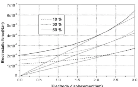
The static actuator performance is characterized by the force equilibrium of the electrostatic driving force and the mechanical spring force. Figure 10 shows the calculated driving force with varing overlap ratio versus moving electrode displacement. The spring force is plotted as a straight line. The moving electrode moves to the intersection of a electrostatic driving force curve and the straight line where electrostatic force and spring force cross. Intersection of the spring force and the electrostatic force indicates equilibrium position.
Above this point pull-in instability which the moving electrode comes into contact with the fixed electrode occur and the actuator is unstable. Thus, under this equilibrium condition, the movable electrode can only one-third of the initial gap in parallel plate actuation [2].
In SEA, the stable stroke can be varied by changing the overlap electrode length. The selection of overlap electrode length has opposite effect on stable stroke and driving force. For decreasing the overlap length, the stable stroke becomes large in SEA. Consequently, the greater the overlap length is, the smaller stable stroke
Fig. 10 Electrostatic force at various overlap electrode length
and the larger driving force become, as shown in figure 10. In figure 11, stable displacement of SEA at various overlap electrode length and Parallel plate actuator are shown. Simulation results show that the proposed SEA generates the stable displacement 20 - 40 % grater than the parallel plate for 0.1 <
< 0.5.Fig. 11 Comparison of stable displacement SEA with parallel plate
3. Application of SEA: Angular Microactuator using SEA
The angular electrostatic microactuator using skewed electrode array(SEA) scheme was designed.
Figure 12 (a) illustrates electrodes arrangement of SEA unit. Each unit of SEA are arranged up to 1mm radius.
Figure 12 (b) illustrates electrodes arrangement for angular actuation. Electrode interval, which is the distance between each electrode pair, is determined by considering the interaction of neighboring electrodes.
The moving electrodes are connected by inner and
stationary electrode
moving electrode
lp
rotation center
g
q
x2 y2 Ls
Ws
f
y1 x1
Wr
Lr
F1y F1x
2y F 2x F
F 2 F1
Anchor Inner ring
Sub branch
Flexural spring
Outer ring Main branch
outer rings lifted on the base substrate, and the inner ring is connected to the flexural suspensions that are anchored to the rotating center. The specification of microactuator is defined in Table 2. Driving moment is proportional to the length of rotating arm of each movable electrode.
(a) Close-up of capacitive electrodes
(b) One quadrant view of the microactuator layout
Fig. 12 Electrodes arrangement of SEA
Fig. 13 Driving torque according to rotation angle
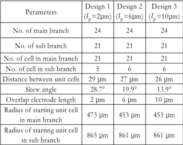
Table 2 Design parameters of angular microactuator
Parameters Design 1 (
=2μm)Design 2 (
=6μm)Design 3 (
=10μm)No. of main branch 24 24 24
No. of sub branch 21 21 21
No. of cell in main branch 21 21 21 No. of cell in sub branch 5 6 6 Distance between unit cells 29 μm 27 μm 26 μm
Skew angle 28.7° 19.9° 13.9°
Overlap electrode length 2 μm 6 μm 10 μm Radius of starting unit cell
in main branch 473 μm 453 μm 453 μm Radius of starting unit cell
in sub branch 865 μm 861 μm 861 μm
As illustrated in equation (12) (13), electrostatic actuators are square law device. A typical approach to linearizing the output force is differential driving which gives
and
to left and right fixed electrode respectively. Using this differential drives and assuming overlap length
constant during the rotation, the total electrostatic force is the difference between the force contributed by the left stationary electrode and right stationary electrode.
cos
sin
(14)
Using Taylor-series expansion, the linear approximation of (14) becomes (15)
(15)where,
cos
sin
cos
sin
In design 2, electrode interval is 27 ㎛ and the number of main and sub branch is 24, 21, respectively.
The number of driving unit cells in main and sub branch is 21, 6 respectively. Consequently, the driving torque is the sum of the unit cell torque
(16)where. is the total number of SEA unit and
is the length of moment arm at each SEA unit.The moving electrodes are coupled to the fixed anchor via mechanical flexures, and the dynamics of the microactuator can be expressed as a second-order system:
(17)where, is the moment of inertia of the moving electrodes of the microactuator, is the damping constant,
is the mechanical spring stiffness of the flexures, and is the electrostatic torque.Substitution of the linearized electrostatic torque from (16) into the actuator equation of motion given in (17) yields a linear dynamic equation for the actuator rotation. The dynamics of microactuator can be described by the equation of motion
(18)Note that
acts to reduce the total spring stiffness of the microactuator. If this electrostatic spring stiffness exceeds the mechanical sparing stiffness
, the dynamic system will be unstable. The stable actuation range is found by setting the electrostatic spring stiffness equals to the mechanical spring stiffness so intersection of the spring force and the electrostatic force in figure 13 indicates equilibrium position.4. Fabrication process
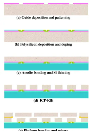
The fabrication process for the angular microactuators is presented in figure 14. First, oxide layer is deposited as a sacrificial layer by PECVD.
After first photolithography, oxide layer is patterned to form mechanical anchor and electrical contact(a). The polysilicon deposited by LPCVD. After second photolithography, polysilicon is selectively doped to achieve electrical contact and insulation(b). CMP is used for planalization of polysilicon layer to bond with glass wafer. The polysilicon layer over the Si-structure is bonded with glass that acts as a base substrate(c).
Subsequently, the silicon is patterned and a high aspect ratio microstructure is achieved by ICP-RIE (d). Then the platform is aligned to bond with the moving electrodes. Finally, the sacrificial layer is chemically etched away using HF and the structure is released (e).
(a) Oxide deposition and patterning
(b) Polysilicon deposition and doping
(c) Anodic bonding and Si thinning
(d) ICP-RIE
(e) Platform bonding and release
Fig. 14 Fabrication process
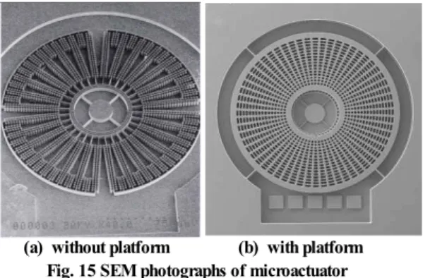
5. Results
A SEM photograph of the fabricated microstructure is shown in figure 15. The microactuator's overall size is 1 mm radius and 0.1 mm thickness. The moving electrodes are connected by inner ring and outer ring lifted on the glass substrate and inner ring is connected to the flexural spring that is anchored to the rotating center.
(a) without platform (b) with platform Fig. 15 SEM photographs of microactuator
The static actuator performance is tested by measuring stable displacement. Figure 16 shows the stable displacement of the microactuator with various overlap electrode length. The greater the overlap length is the smaller stable stroke. The measured stable displacement differs slightly from the simulated values for the following reasons. First, the flexural spring width was slightly narrower than designed, resulting in reduction of the mechanical stiffness of the microactuator. Secondly, the microactuator height was reduced during CMP process which lowers in-plane stiffness of the flexural spring.
Fig. 16 Stable displacement at various overlap length
6. Conclusions
The movable and fixed electrodes are arranged to make the driving force perpendicular to the rotating moment of arm. By changing the electrode overlap length, the magnitude of electrostatic force and stable displacement will be changed. In order to optimize the design, electrostatic FE analysis were carried out and the empirical force model was established for SEA.
Simulation was performed to make the comparison between the conventional type and the SEA. The proposed SEA generates actuating torque 2 times greater than the comb-drive and stable actuator displacement 40% greater than the parallel plate. The angular electrostatic microactuator using skewed electrodes array (SEA) scheme was designed and fabricated using SoG process.
References
[1] Tang, W. C., 1990, "Electrostatic Comb Drive for Resonant Sensor and Actuator Applications" Ph.
D. Dissertation, University of California Berkeley [2] Joseph I. Seeger and Selden B. Cray,"
Stabilization of Electrostatically Actuated Mechanical Devices", TRANDUCERS '97, Chicago, 1997
[3] D. W. Cho, J. Y. KIM, S. J. Lee, S. M. Choi, "A Microactuator for High-Density Hard Disk Drive", ASME 2000, MEMS-Vol.2, pp.307-312, 2000 [4] D. Horlsey, A. Singh, A.P. Pisano and R.
Horowitz, "Angular micro- positioner for disk drives", Proc. IEEE MEMS Workshop, 1997, pp.223-233
[5] Horsey, D. A., Wongkomet, N., Horowitz, R., Pisano, A. P. "Precision positioning using a microfabricated electrostatic actuator, IEEE Transactions on Magnetics, Vol. 35, No. 2, 1999, pp. 993-999
[6] S. Zappe, M. Baltzer, Th Kraus and E Obermeier, "Electrostatically driven linear micro-actuators: FE analysis and fabrication", J.
Micromech. Microeng. 7, 1997, pp.204-209 [7] Maxwell 2D Field Simulator, ANSOFT