https://doi.org/10.3341/jkos.2018.59.7.691
Case Report
유두주위오목으로의 망막탈출에 의한 시신경섬유층 결손 1예
A Case of Retinal Herniation through Peripapillary Pit Resulting in Retinal Nerve Fiber Layer Defect
박재용⋅오원혁
Jae Yong Park, MD, Won Hyuk Oh, MD
인제대학교 의과대학 상계백병원 안과학교실
Department of Ophthalmology, Sanggye Paik Hospital, Inje University College of Medicine, Seoul, Korea
Purpose: To report a case of glaucoma suspect with peripapillary pit, which enlarged in size with retinal herniation through the pit, and resulted in retinal nerve fiber layer defect and corresponding visual field defect.
Case summary: A 34-year-old male was referred to our glaucoma clinic for glaucoma evaluation. The intraocular pressure was 15 mmHg in the right eye and 14 mmHg in the left eye. The refractive error in spherical equivalence was -12.75 diopters (D) in the right eye and -11.50 D in the left eye. The axial length was 28.70 mm in the right eye and 28.15 mm in the left eye. On optical co- herence tomography (OCT), the retinal nerve fiber layer thickness was within normal limits in both eyes. A peripapillary pit was found in both eyes, which measured 155 μm in the right eye and 625 μm in the left eye in maximal horizontal diameters. Two year follow-up OCT images showed that the peripapillary pit in the right eye enlarged to 239 μm and retinal herniation occurred through the pit, resulting in a retinal nerve fiber layer defect and a corresponding visual field defect. However, the peripapillary pit in the left eye had no significant change.
Conclusions: Glaucoma patients or suspects, with peripapillary pits need close observation because of the possibility of a retinal nerve fiber layer defect in the direction of the pit.
J Korean Ophthalmol Soc 2018;59(7):691-696
Keywords: Peripapillary pit, Retinal herniation, Retinal nerve fiber layer defect
■Received: 2017. 11. 2. ■ Revised: 2018. 5. 1.
■Accepted: 2018. 6. 25.
■Address reprint requests to Won Hyuk Oh, MD
Department of Ophthalmology, Inje University Sanggye Paik Hospital, #1342 Dongil-ro, Nowon-gu, Seoul 01757, Korea Tel: 82-2-950-8866, Fax: 82-2-950-1930
E-mail: [email protected]
* Conflicts of Interest: The authors have no conflicts to disclose.
ⓒ2018 The Korean Ophthalmological Society
This is an Open Access article distributed under the terms of the Creative Commons Attribution Non-Commercial License (http://creativecommons.org/licenses/by-nc/3.0/) which permits unrestricted non-commercial use, distribution, and reproduction in any medium, provided the original work is properly cited.
유두주위오목은 유두주위 영역에 위치한 구멍 모양의 구조물로, 최근 고도근시와의 연관이 보고되었다.1 후천시 신경유두오목은 시신경유두에 위치한 구조물로, 녹내장 진 행의 중요한 위험인자로 잘 알려져 있지만,2 유두주위 오 목의 발생기전과 임상적 의미에 대해서는 아직까지 잘 알
려져 있지 않다.1 고도근시 환자에서 유두주위공막 팽창이 유두주위오목의 일차적인 원인이라는 가설이 제기되었으 나, 이를 뒷받침할 만한 연구결과는 아직까지 많지 않다.
게다가 유두주위오목의 자연경과에 대하여서는 아직까지 알려진 바가 거의 없다.1,3 저자들은 녹내장의증으로 경과 관찰하던 환자에서 단안의 유두주위오목이 커지면서 그 방향으로 망막이 탈출하여 시신경섬유층결손과 이에 동반 된 시야장애가 나타났지만, 반대안의 유두주위오목에는 변 화가 없었던 증례를 경험하였기에 이를 보고하고자 한다.
A B
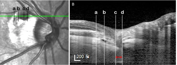
Figure 1. The infrared image (A) and optical coherence tomography (OCT) enhanced depth image (B) describing the location and the measurement of the peripapillary pit of the right eye. The size of the pit was measured in the OCT scan crossing the maximal horizon- tal diameter of the pit. The distance between the vertical lines passing the edge where the inner scleral continuity ends (c, d) was meas- ured (red left right arrow). The peripapillary pit of the right eye was located in the gamma zone of the peripapillary atrophy (PPA), corresponding to the area between the optic disc border and the edge of the Bruch’s membrane (b). The beta zone PPA is depicted as the area between the edge of the Bruch’s membrane (b) and the end of the retinal pigment epithelium layer (a).
증례보고
34세 남자 환자가 녹내장의증으로 본원 녹내장 클리닉으 로 의뢰되었다. 환자의 최대교정시력은 양안 모두 20/20이 었다. 안압은 우안 15 mmHg, 좌안 14 mmHg, 중심각막두께 는 우안 491 μm, 좌안 501 μm였다. 자동굴절검사상 우안 -12.50 Dsph = -0.50 Dcyl 축 30°, 좌안 -11.25 Dsph = -0.75 Dcyl 축 145°였으며, 부분결합간섭원리를 이용한 안구생체 계측계인 AL-scan (Nidek Co., Ltd, Gamagori, Japan)으로 측 정한 안축장은 우안 28.70 mm, 좌안 28.15 mm였다. 세극등 검사에서는 양안 모두 전안부에서 특이 소견이 관찰되지 않았다. 안저검사에서 양안의 유두주위오목 및 주변부 망막 에서 다수의 격자 변성이 관찰되었다. 스펙트럼영역 빛간섭 단층촬영기(spectral domain optical coherence tomography;
Spectralis, Heidelberg Engineering, Heidelberg, Germany)로 시신경유두 중심 15° × 10° 크기의 가로방향 B-스캔으로 깊 이증강영상(enhanced depth image)을 획득하여 유두주위오 목을 분석하였다. 우안의 유두주위오목은 시신경 상이측의 감마영역(γ zone) 유두주위위축에 위치하였으며(Fig. 1), 그 주변으로 엘쉬니히 경계조직 및 공막의 결손이 있었다(Fig.
2A, B). 공막결손 아래로 공막 내 공간이 존재하였고, 이는 공막연결부(scleral flange) 아래의 거미막밑공간과 연결되어 있었다(Fig. 2E, F). 좌안의 유두주위 목은 시신경 하이측의 베타영역(β zone) 유두주위위축의 바깥 경계보다 밖으로 위 치하였고, 망막색소상피/브루크막 복합체 및 맥락막혈관의 결손이 관찰되었다. 결손 방향으로 망막탈출이 발생하여 시
세포층 및 바깥경계막 등 주로 바깥망막층 결손과 함께 망 막표면에서 얕은 오목의 모습을 보이고 있었다. 유두주위오 목의 크기는 적외선영상에서 타원형의 저음영으로 보이는 유두주위오목의 수평직경이 최대가 되는 위치의 깊이증강 빛간섭단층영상에서 오목 내 구조물 결손 부위의 이측 및 비측 경계를 찾아 수직선을 긋고, 그 사이의 거리를 뷰어프 로그램(Heidelberg Eye Explorer, Heidelberg Engineering, Heidelberg, Germany)에 내장된 측정기로 최대수평직경을 측정하였다(Fig. 1). 우안 유두주위오목의 최대수평직경은 155 μm (Fig. 1), 좌안 유두주위오목의 최대수평직경은 625 μm 였다(Fig. 2I, J). 망막신경섬유층촬영 및 빛간섭단층촬영에 서 망막신경섬유층결손은 양안에서 없었고(Fig. 3A, B), 표 준시야검사에서 정상이었다(Fig. 4A).
2년 뒤 시행한 같은 위치를 촬영한 깊이증강 빛간섭단층 촬영에서 우안 유두주위오목의 최대수평직경은 239 μm로 증가하면서 유두주위오목은 더 깊어지고, 그 방향으로 망막 탈출이 더 심해졌다. 그 과정에서 베타영역 유두주위위축 안에 있는 망막색소상피/브루크막 복합체의 주행이 시신경 유두 중심 방향으로 좀 더 경사가 급해지고, 유두주위위축 위 및 그 바로 바깥쪽의 망막두께는 감소하였다(Fig. 2D). 적 외선영상에서는 유두주위오목의 상측 및 이측으로 베타영 역 유두주위위축이 확장되면서, 인근 망막정맥의 주행이 변 한 것을 확인할 수 있었다(Fig. 2C). 또한 공막결손 및 공막 내공간의 크기가 커지면서(Fig. 2G, H), 유두주위위축 바깥 쪽으로 바깥망막층의 층간분리가 관찰되었다(Fig. 2D). 망막 신경섬유층촬영에서 유두주위오목이 위치한 상이측 방향으
A B
C D
E F
G H
I J
K L
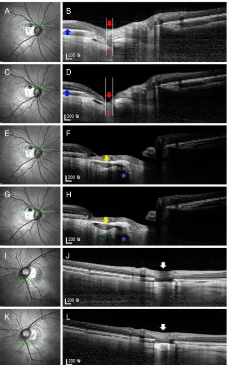
Figure 2. The infrared fundus image (A, C, E, G, I, K), optical coherence tomography (OCT) enhanced depth images (EDI) (B, D, F, H, J, L) at the first visit (A, B, E, F, I, J) and 2 years after the first visit (C, D, G, H, K, L). (A, B) Infrared fundus image and OCT EDI of the right eye at the first visit, respectively. The red arrow indicates the peripapillary pit of the right eye. The red left right arrow indicates the extent of the peripapillary pit. The blue arrow indicates the intact outer retinal layers at the first visit. (C) Infrared fundus image of the right eye at 2 years after the first visit shows the change in the route of superotemporal retinal vein. (D) OCT EDI of the right eye at 2 years after the first visit, which is the same scan location to B. Note the deepening of the pit and retinal herniation through the pit (red arrow) and the development of retinoschisis (blue arrow). The red left right arrow indicates the extent of the peri- papillary pit. (E) Infrared fundus image of the right eye at the first visit. (F) OCT EDI of the right eye at the first visit. The yellow arrow indicates the intrascleral space connected to the subarachnoid space (purple star) beneath the scleral flange. (G) Infrared fundus image of the right eye at 2 years after the first visit. (H) OCT EDI of the right eye at the 2 years after the first visit, which is the same scan location to F. Note the enlargement of intrascleral space compared to that of F (yellow arrow). Intrascleral space is connected to the subarachnoid space (purple star) via intrascleral channels (small green arrows), which are more prominent than that seen in F.
(I, J) Infrared fundus image and OCT EDI of the left eye at the first visit, respectively. The peripapillary pit is seen as well (white ar- row). (K, L) Infrared fundus image and OCT EDI of the left eye at 2 years after the first visit, respectively. There is no interval change compared to the first visit (I, J). The white arrow indicates the peripapillary pit, which shows no interval changes from J.
A B
C D
Figure 3. Red-free fundus photograph (A, C) and circumpapillary optical coherence tomography (OCT) scan (B, D) at the first visit and at 2 years after the first visit, respectively. (A) Retinal nerve fiber layer (RNFL) defect is not evident on red-free fundus photograph. (B) Retinal nerve fiber layer atrophy is not also evident in OCT scan. (C) The wedge-shaped RNFL defect (between white arrows) is found in the direction of the peripapillary pit. (D) A focal RNFL atrophy is also found in OCT scan (thick white ar- row), which is matched with RNFL defect shown in C.
1
A B
30 30
Figure 4. Humphrey visual field test before and after the retinal herniation through the peripapillary pit. (A) Visual field defect is not evident before the retinal herniation. (B) Corresponding inferior paracentral scotoma is obvious after the retinal herniation through the peripapillary pit.
로 명확한 망막신경섬유층결손이 관찰되었으며(Fig. 3C), 빛 간섭단층촬영에서도 이를 확인할 수 있었다(Fig. 3D). 시야 검사에서 상이측의 망막신경섬유층 결손과 일치하는 하측 중심부근암점을 확인할 수 있었다(Fig. 4B). 하지만, 좌안의 유두주위오목에서는 안저사진, 적외선안저영상 및 빛간섭 단층촬영 모두에서 변화가 관찰되지 않았다(Fig. 2I-L).
고 찰
유두주위오목은 안저영상기술의 발전으로 비교적 최근 에 임상적으로 주목 받고 있는데, 기존의 안저사진보다는 적외선안저촬영 및 빛간섭단층촬영을 통해 명확하게 관찰 할 수 있게 되었기 때문이다. 기존의 유두주위오목의 해부 학적인 구조를 파장가변광원 빛간섭단층촬영을 사용하여 분석한 연구에 따르면 유두주위오목은 짧은뒤섬모체동맥이
공막을 통과하는 경로가 공막신장(scleral stretching)에 의해 확장되어 발생하는 것 같다고 저자들은 주장하였다.1 본 증 례의 환자에서 유두주위오목이 양안에서 발견되었으며 2년 뒤 시행했던 검사에서는 우안의 유두주위오목이 커지면서 그 방향으로 망막탈출이 진행하여, 그 결과로 망막신경섬유 층결손과 이에 상응하는 시야장애가 발생하였다. 또한 유두 주위위축 바깥쪽으로 바깥망막층의 층간분리가 발생하였 다. 이는 시신경유두오목에서 발생하는 망막층간분리4의 초 기 모습과 매우 유사한 형태로 아직까지 보고된 바 없다. 시 신경유두오목에서 발생하는 망막층간분리는 액화된 유리체5 혹은 뇌척수액6이 망막 하로 들어가면서 발생한다고 알려 져 있다. 유두주위오목 주변을 촬영한 빛간섭단층촬영에서 유리체와 접하는 내층망막의 결손이 명확하지 않았던 점을 고려했을 때, 거미막밑공간의 뇌척수액이 기존의 공막 내 공간과 연결된 통로를 통해 안구 내로 더 많이 유입되어, 공 막 내 공간을 확장시키고, 그 중 일부가 바깥망막층으로 들 어가 망막층간분리를 유발한 것으로 보인다.
이러한 변화가 경과관찰하던 2년간 점진적으로 발생하였 는지, 갑자기 발생하였는지, 혹은 향후 계속 진행할 것인지 는 확실하지 않다. 본 증례의 경우 유두주위오목으로 망막 이 탈출하면서 오목 주변으로 주로 망막신경섬유층이 매우 얇아졌지만 망막이 완전히 단절되지는 않았다. Ohno- Matsui et al1은 앞서 언급된 발표에서 여러 형태의 유두주 위오목의 증례를 보여주었는데, 한 예를 제외하고는 오목 주변으로 망막이 완전하게 단절되었다고 보고하였다. 본 증 례에서 오목 주변으로 완전한 망막의 단절이 보이지 않은 것은 오목으로 망막탈출이 일어난 지 얼마 되지 않았기 때 문일 수도 있다. 그렇기 때문에 유두주위오목이 있는 환자 에서 면밀한 경과관찰이 필요하며, 언젠가는 오목으로의 망 막탈출이 진행하여 오목을 경계로 망막신경섬유층 혹은 결 국에는 망막 전층의 결손이 발생하여 시야결손이 생길 수 있음을 염두에 두어야 하겠다. 또한 시신경유두오목에서와 같이 유두주위오목에서도 액화된 유리체 혹은 뇌척수액이 망막 내 유입되어 망막층간분리 혹은 장액성망막박리가 발 생할 수 있다는 점도 고려해야겠다.
흥미로운 사실은 우안은 유두주위오목이 커지면서 망막 탈출이 진행하는 동안 좌안의 유두주위오목에는 변화가 없 었다는 점이다. 경과관찰 중 안압은 양안 간에 유의한 차이 가 없었다. 본 저자들은 이러한 차이를 다음의 가설로 설명 하고자 한다. 우선 우안의 유두주위오목은 유두주위위축 안 에 위치하고 있었던 반면, 좌안에서는 유두주위위축 바깥쪽 에 위치하고 있었다. 유두주위위축은 망막색소상피와 맥락 막모세혈관의 위축에 의해 발생하여 공막과 맥락막혈관이 보이는 부분이다.7,8 우안의 유두주위오목은 특히 브루크막
의 지지가 없는 감마영역 유두주위위축 내에 위치하고, 동 시에 엘쉬니히 경계조직 및 공막의 결손이 동반되는 등 주 변 조직의 지지가 약해서 공막 신장에 의한 물리적인 장력 에 더 취약했을 가능성이 있다. 또한 우안의 안축장은 28.70 mm로 좌안보다 0.55 mm 더 길었다. 이러한 이유로 비슷한 안압에도 불구하고 우안의 유두주위오목에 작용하는 변형 (strain)의 힘 자체가 더 컸을 가능성도 있다. 따라서 우안 유 두주위오목의 크기 증가 속도가 좌안보다 더 빨라 그 방향 으로 망막탈출이 더 진행하였을 것이다.
그런데 본 증례에서 유두주위오목의 크기를 측정할 때 우안은 오목 밑 공막결손부 안쪽의 최대수평직경을, 좌안은 오목 밑의 망막색소상피/브루크막 복합체 결손부의 최대수 평직경을 측정하여 그 기준점이 달랐다. 그리고 우안에서는 적외선안저영상에서 시신경유두오목이라 생각되는 유두주 위위축 안의 저음영의 경계와 실제 빛간섭단층촬영에서 보 이는 해부학적 결손부의 경계(망막색소상피/브루크막 복합 체 및 공막 수준)는 서로 일치하지 않았다. 이러한 점에서 유두주위오목의 크기를 측정할 때 기준점을 어디에 두어야 하는지에 대한 논의가 향후에 필요하겠다.
결론적으로 유두주위오목으로의 망막탈출은 흔치 않은 증례로 유두주위오목이 있는 녹내장 또는 녹내장의증 환자 에서 오목의 방향으로 망막탈출이 일어날 경우 시신경섬유 층 혹은 망막 전층의 결손이 발생하여 시야결손이 발생할 수 있으므로 면밀한 경과관찰이 필요하다.
REFERENCES
1) Ohno-Matsui K, Akiba M, Moriyama M, et al. Acquired optic nerve and peripapillary pits in pathologic myopia. Ophthalmology 2012;119:1685-92.
2) Ugurlu S, Weitzman M, Nduaguba C, Caprioli J. Acquired pit of the optic nerve: a risk factor for progression of glaucoma. Am J Ophthalmol 1998;125:457-64.
3) Lee EJ, Kim TW. Progressive retinal nerve fiber layer atrophy asso- ciated with enlarging peripapillary pit. J Glaucoma 2017;26:e79-81.
4) Kranenburg EW. Crater-like holes in the optic disc and central se- rous retinopathy. Arch Ophthalmol 1960;64:912-24.
5) Dithmar S, Schuett F, Voelcker HE, Holz FG. Delayed sequential occurrence of perfluorodecalin and silicone oil in the subretinal space following retinal detachment surgery in the presence of an optic disc pit. Arch Ophthalmol 2004;122:409-11.
6) Krivoy D, Gentile R, Liebmann JM, et al. Imaging congenital optic disc pits and associated maculopathy using optical coherence tomography. Arch Ophthalmol 1996;114:165-70.
7) Jonas JB, Nguyen XN, Gusek GC, Naumann GO. Parapapillary chorioretinal atrophy in normal and glaucoma eyes. I. Morphometric data. Invest Ophthalmol Vis Sci 1989;30:908-18.
8) Jonas JB. Clinical implications of peripapillary atrophy in glaucoma. Curr Opin Ophthalmol 2005;16:84-8.
= 국문초록 =
유두주위오목으로의 망막탈출에 의한 시신경섬유층 결손 1예
목적: 녹내장의증으로 경과 관찰하던 환자에서 유두주위오목이 커지면서 그 방향으로 망막이 탈출하여, 시신경섬유층 결손과 함께 연관된 시야장애가 나타난 증례를 경험하였기에 이를 보고하고자 한다.
증례요약: 34세 남자 환자가 녹내장의증으로 본원 녹내장 클리닉으로 의뢰되었다. 환자의 안압은 우안 15 mmHg, 좌안 14 mmHg였다.
굴절이상은 구면렌즈대응치로 우안 -12.75디옵터, 좌안은 -11.50디옵터였으며, 안축장은 우안 28.70 mm, 좌안 28.15 mm였다. 빛간섭 단층촬영에서 망막신경섬유층의 두께는 양안 모두 정상 범위 안에 있었다. 양안에서 유두주위오목이 관찰되었으며, 최대수평직경은 우안 155 μm, 좌안 625 μm였다. 2년 뒤 시행한 빛간섭단층촬영에서 우안 유두주위오목은 239 μm로 커지면서 그 방향으로 망막이 탈출하여 시신경섬유층결손 및 이에 상응하는 시야장애가 발생하였다. 하지만 좌안 유두주위오목에는 변화가 없었다.
결론: 유두주위오목이 있는 녹내장 또는 녹내장의증 환자에서 유두주위오목 방향으로 시신경섬유층결손이 발생할 수 있으므로 면밀 한 경과관찰이 필요하다.
<대한안과학회지 2018;59(7):691-696>