• 검색 결과가 없습니다.

In-Situ Heat Cooling using Thick Graphene and Temperature Monitoring with Single Mask Process

N/A
N/A
Protected

Academic year: 2021

Share "In-Situ Heat Cooling using Thick Graphene and Temperature Monitoring with Single Mask Process"

Copied!
4
0
0

로드 중.... (전체 텍스트 보기)

전체 글

(1)

155 J. Sensor Sci. & Tech. Vol. 24, No. 3, 2015 Journal of Sensor Science and Technology

Vol. 24, No. 3 (2015) pp. 155-158 http://dx.doi.org/10.5369/JSST.2015.24.3.155 pISSN 1225-5475/eISSN 2093-7563

In-Situ Heat Cooling using Thick Graphene and Temperature Monitoring with Single Mask Process

Kyuhyun Kwack

1,+

and Kukjin Chun

2

Abstract

In this paper, in-situ heat cooling with temperature monitoring is reported to solve thermal issues in electric vehicle (EV) batteries.

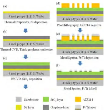
The device consists of a thick graphene cooler on top of the substrate and a platinum-based resistive temperature sensor with an embed- ded heater above the graphene. The graphene layer is synthesized by using chemical vapor deposition directly on the Ni layer above the Si substrate. The proposed thick graphene heat cooler does not use transfer technology, which involves many process steps and does not provide a high yield. This method also reduces the mechanical damage of the graphene and uses only one photomask. Using this structure, temperature detection and cooling are conducted simultaneously using one device. The temperature coefficient of resistance (TCR) of a 1 ×1 mm

2

temperature sensor on 1-ìm-thick graphene is 1.573 ×10
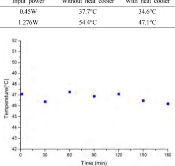
3

ppm/°C. The heat source cools down 7.3°C from 54.4°C to 47.1°C.

Keywords: Thick Graphene, Heat Cooler, Temperature Sensor, TCR, Single Mask Process

1. INTRODUCTION

Thermal issues in electric vehicle (EV) batteries or 3D integrated circuits (ICs) have become more important. For batteries for EV applications, the energy storage capacity is reduced by 35%, when the operating temperature of the battery cell increased to 55°C. The storage capacity is also reduced operating temperatures of less than -20°C. An exothermic reaction in the battery can form hotspots, which could result in self-heating or asymmetrical current flow. In addition, the hotspots are the prime cause of thermal runaway, which could cause an explosion of the battery. To ensure the lifetime, performance, and safety of the battery, the operating temperature range of 35°C - 40°C should be maintained using thermal management [1-3]. For battery thermal management in EVs, research on temperature sensors to monitor the temperature of the battery cell surface and on the cooling layer of the graphite sheet on the battery cell surface to

cool down the temperature are in progress. However, in these studies, temperature monitoring and heat cooling require two separate devices [4-6]. For 3D ICs, as the integration density increases, the heat density also increases. The small footprint results in a small amount of heat spreading over a small heat sink area, which cannot effectively cool down the chip. To cool down the generated heat in the chips, heat spreading or heat sink structures are necessary [7].

To overcome these thermal issues, many studies using graphene, which exhibits high thermal conductivity have been reported [8-11]. At Chalmers University of Technology, the temperature of the heat source decreased from 121°C to 108°C using a mono layer of graphene synthesized on a Cu thin film using chemical vapor deposition (CVD). The graphene was transferred using a ploymethyl methacrylate PMMA) supported wet chemical process. At Seoul National University, the heat source temperature was reduced from 57.49°C to 48.43°C using thick graphene synthesized on Ni foil transferred using thermal release tape (TRT) and hot pressing. These studies were conducted using the conventional transfer method, which involves five process steps. This conventional transfer method has some disadvantages. The graphene layer is difficult to align on the target substrate because the transfer is conducted manually. In addition, after transferring, the graphene layer is not attached perfectly on the substrate. These disadvantages result in a low yield and low thermal management performance.

1

Dept. of Electrical and Computer Engineering, Seoul National University, 1 Gwanak-ro, Gwanak-gu, Seoul 151-742, Korea

2

Dept. of Electrical and Computer Engineering, Seoul National University, 1 Gwanak-ro, Gwanak-gu, Seoul 151-742, Korea

+

Corresponding author: [email protected] (Received : May. 12, 2015, Accepted : May. 26, 2015)

This is an Open Access article distributed under the terms of the Creative Commons Attribution Non-Commercial License(http://creativecommons.org/

licenses/bync/3.0) which permits unrestricted non-commercial use, distribution,

and reproduction in any medium, provided the original work is properly cited.

(2)

Kyuhyun Kwack and Kukjin Chun

J. Sensor Sci. & Tech. Vol. 24, No. 3, 2015 156 In this paper, with the in-situ heat-cooling layer of thick graphene in a temperature-monitoring sensor, multiple-functions, i.e., monitoring the temperature in real time and cooling down of the generated heat, can be performed simultaneously using only one device. To fabricate a thick graphene heat cooler, a thick layer of graphene was synthesized directly using CVD on the Ni layer above a Si wafer. After the synthesis, a dielectric layer was deposited, and the temperature sensor was fabricated. The heat- cooling layer using graphene on the substrate process step was reduced to two steps, Ni layer deposition, and graphene synthesis.

Because the Ni layer was not eliminated, the graphene layer adhered to the substrate completely. This method can overcome the low yield of the conventional transfer method.

2. DESIGN AND FABRICATION

Fig. 1 shows the device schematic. The Ni layer above the substrate plays an important role as a seed layer to synthesize the thick graphene layer. The SiO

2

layer is deposited for insulation and planarization on the graphene layer. The temperature sensor on the SiO

2

layer is the resistance temperature detector (RTD) type. The sensor surrounds the embedded heater. The sensor material is platinum, which exhibits a high melting point, stability, and linearity. Based on the resistance changes with temperature in Eq.

(1), the sensor detects the temperature:

(1)

The device was fabricated on a 4-inch Si wafer. The heat- cooling layer using 1-ìm-thick graphene was synthesized by CVD on the Ni layer above the Si substrate. The platinum- based temperature sensor was fabricated using a one-mask simple

process on the graphene cooling layer.

Fig. 2 shows the fabrication process. For fabricating a thick graphene layer, a 500-nm-thick Ni layer was deposited using a thermal evaporator. Then, 1-μm-thick graphene was synthesized using thermal CVD followed by the deposition of a 1-μm-thick SiO

2

layer for insulation and planarization. To make the sensor pattern, a Pt/Ti layer was deposited by sputtering, and the temperature sensor was prepared using the lift-off process. Two samples were prepared to measure the temperature cooling: one with 1-μm-thick graphene and the other with no graphene.

3. RESULTS AND DISCUSSION

The resistance of the temperature sensor was measured to calculate the TCR using Eq. (1) according to the change in the temperature. The measurements were performed using the same power applied to the embedded heater both with and without the graphene cooling layer followed by calculating the sensing temperature.

TCR dR --- dT 1

R

o

---

×

=

Fig. 1. Device schematic.

Fig. 2. Fabrication process of in-situ heat cooling layer in temper- ature monitoring sensor system

(a) 500-nm-thick Ni layer deposition using thermal evapo- rator for graphene synthesis

(b) Thick graphene synthesis using thermal CVD (c) SiO

2

deposition for insulation and planarization (d) Photolithography for temperature sensor pattern (e) 100 nm / 20-nm-thick Pt / Ti deposition (f) Lift-off procedure for Pt/Ti temperature sensor.

I 12 I

(3)

In-Situ Heat Cooling using Thick Graphene and Temperature Monitoring with Single Mask Process

157 J. Sensor Sci. & Tech. Vol. 24, No. 3, 2015 3.1 Sensor characteristic

The RTD type sensor was characterized by TCR. Fig. 3 displays the resistance measurements for the same sensor with the temperature ranging from -9°C to 90°C, where the temperature was measured 5 times. The device uses graphene as a heat-cooling layer and shows good linearity as well as repeatability. The average value of the resistance at 20°C was 827 Ω. The maximum difference for five measurements was 3 Ω, which was less than 1%. The average value of dR/dT, which was calculated from the slope of the linear graph, was 1.3Ω/°C. Each dR/dT value has an error range of less than 4.6% from the average value.

As the temperature increased, the resistance of the temperature sensor also increased linearly, and the average correlation coefficient was 0.99. The average TCR, which was calculated using Eq. (1), was 1.573×10

3

ppm/°C.

3.2 Temperature cooling

The temperature cooling could be measured using the two samples mentioned in section 2 above. The same power was applied to the embedded heater of each structure, and the sensor resistances, Ro and ΔR, were measured for both samples, which can be converted to a temperature change of the heater for both cases with and without the graphene cooling layer, as shown in Eq. (2). In this calculation, the TCR from Eq. (1) is used.

(1)

(2) The TCRs of both samples were 1.573 ×10

3

ppm/

o

C and 1.764

×10

3

ppm/

o

C with and without graphene, respectively. A power of 1.276 W was applied to the embedded heater of the sample without graphene to increase the temperature to 54.4°C. The temperature of the device with the graphene heat cooler was 47.1°C. The temperature cooling was 7.3°C, which is the temperature difference between the samples. The same measurement was performed for a lower power of 0.45 W. Table 1 shows the temperature cooling based on the heat cooling effect of graphene due to its very high thermal conductivity. Therefore, we can expect larger cooling for a higher operating temperature.

The cooling performance of the device over time was also characterized by maintaining the input power of the device at 1.276 W for 3 h. The temperature fluctuation was less than 1.3%, as observed in Fig. 4.

4. CONCLUSIONS

In this paper, in-situ heat cooling using a thick graphene layer with simultaneous temperature monitoring was proposed to solve thermal issues in EV batteries or ICs. This simple device exhibits two functions simultaneously: real-time temperature detection and cooling down of the heat source. While measuring the temperature ΔT

w heatcooler⁄

R

w heatcooler⁄

Δ

TCR

w heatcooler⁄

× R

o w heatcooler, ⁄

---

=

ΔT

w o _heatcooler⁄

R

w o _heatcooler⁄

Δ

TCR

w o _heatcooler⁄

× R

o w o _heatcooler, ⁄

---

= Fig. 3. Resistance vs. temperature characteristic of the sensor

Table 1. Temperature according to the input power

Input power Without heat cooler With heat cooler

0.45W 37.7°C 34.6°C

1.276W 54.4°C 47.1°C

Fig. 4. Temperature of the sensor with heat cooler structure vs. time.

I 13 I

(4)

Kyuhyun Kwack and Kukjin Chun

J. Sensor Sci. & Tech. Vol. 24, No. 3, 2015 158 for 3 h, the heat cooler can also cool the heat source.

The heat cooler of the thick graphene layer was synthesized using CVD directly on the Ni layer above the Si substrate. The heat cooler does not use the conventional transfer method.

Therefore, it could reduce mechanical damage of the graphene as well as the number of processing steps.

The platinum-based temperature sensor was fabricated by a single mask simple process on a thick graphene cooler. It exhibited good linearity and repeatability. With the power of 1.276 W, the heater temperature cooled down by 7.3°C with very little fluctuation.

ACKNOWLEDGMENT

This work was supported by the Hyundai Next Generation Vehicle Technology, Hyundai Motor Company, and Inter- university Semiconductor Research Center (ISRC).

REFERENCES

[1] Bandhauer, T. M., Garimella, S., and Fuller, T. F. “A critical review of thermal issues in lithium-ion batteries”, Journal of the Electrochemical Society, Vol. 158, No. 3, pp. R1-R25, 2011.

[2] Chacko, S., and Chung, Y. M. “Thermal modelling of Li- ion polymer battery for electric vehicle drive cycles”, Jour- nal of Power Sources, Vol. 213, pp. 296-303, 2012.

[3] Kim, U. S., Shin, C. B., and Kim, C. S. “Modeling for the scale-up of a lithium-ion polymer battery”, Journal of Power Sources, Vol. 189, No. 1, pp. 841-846, 2009.

[4] Lorentz, V. R. H., Wenger, M. M., Grosch, J. L., Giegerich, M., Jank, M. P. M., Marz, M., and Frey, L. “Novel cost-effi- cient contactless distributed monitoring concept for smart battery cells”, Industrial Electronics (ISIE), 2012 IEEE International Symposium on. IEEE, pp. 1342-1347, 2012.

[5] http://arpa-e.energy.gov/?q=slick-sheet-project/thin-film- temperature-sensors-batteries (retrieved on Apr. 3, 2012) [6] https://www.google.com/patents/US20130183566?dq=

Thermal+Management+Structures+for+Battery+Packs&hl

=ko&sa=X&ei=d-FCVeKWJeXOmwW84IDwDA&ved=

0CB0Q6AEwAA(retrieved on Apr. 3, 2012)

[7] Fukushima, T., T. Tanaka, and M. Koyanagi. “Thermal Issues of 3D ICs”, Proceedings: Design for Reliability Workshop-Stress Management for 3D ICs Using Through Silicon Vias, SEMATECH. 2007.

[8] Pop, E., Mann, D., Wang, Q., Goodson, K., and Dai, H.

“Thermal conductance of an individual single-wall carbon nanotube above room temperature”, Nano letters, Vol. 6, No. 1, pp. 96-100, 2006.

[9] Balandin, A. A., Ghosh, S., Bao, W., Calizo, I., Teweld- ebrhan, D., Miao, F., and Lau, C. N. “Superior thermal con- ductivity of single-layer graphene”, Nano letters, Vol. 8, No. 3, pp. 902-907, 2008.

[10] Gao, Z., Zhang, Y., Fu, Y., Yuen, M. M., and Liu, J. “Ther- mal chemical vapor deposition grown graphene heat spreader for thermal management of hot spots”, Carbon, 61, pp. 342-348, 2013.

[11] W.K. Choi, “Analysis of Heat Transfer Characteristics of single chip using thick graphene”, Seoul National Uni- versity, Master degree thesis, 2014.

I 14 I

수치

Fig. 1 shows the device schematic. The Ni layer above the substrate plays an important role as a seed layer to synthesize the thick graphene layer
Fig. 4. Temperature of the sensor with heat cooler structure vs. time.

참조

관련 문서

This study reports sensitivity enhancement method of a temperature sensor based on fiber Bragg grating (FBG) in combination with an auxiliary materials with a

In this study, the mercury in exhaust gas was measured from three large coal-fired power plants in Korea using the continuous emission monitoring system

▪ Local temperature of PMSM can be calculated through thermal resistance model and heat generation model, presenting the cooling performance thermal

For this reason, in this study, comparing the traditional manufacturing process and relatively high temperature of exhaust gas heat and CO2 laser

As a result of comparing with the temperature change, the coldest month mean temperature (January, February, December) showed positive value in the whole

A PID control with Feedfoward Controller for Controlling Fluid Temperature in Heat Exchanger.. 지도교수

Fig.11 Temperature histories of the hot side and cold side heat exchangers according to time with speaker power(10W).. Fig.12 Temperature histories of the hot

Vacuum pre-cooling system's principle is that water saturated temperature is lowered according to the vacuum pressure established in the storage chamber,