Nanofibers as High-Rate and
Long-Cycle-Life Anode Material for
Sodium Ion Batteries
Yeolmae Yeo1, Ji-Won Jung1, Kyusung Park2 & Il-Doo Kim1Anatase TiO2 has been suggested as a potential sodium anode material, but the low electrical
conductivity of TiO2 often limits the rate capability, resulting in poor electrochemical properties. To
address this limitation, we propose graphene-wrapped anatase TiO2 nanofibers (rGO@TiO2 NFs)
through an effective wrapping of reduced graphene oxide (rGO) sheets on electrospun TiO2 NFs. To
provide strong electrostatic interaction between the graphene oxide (GO) sheets and the TiO2 NFs,
poly(allylamine hydrochloride) (PAH) was used to induce a positively charged TiO2 surface by the
immobilization of the -NH3+ group and to promote bonding with the negatively charged carboxylic acid
(-COO−) and hydroxyl (-O−) groups on the GO. A sodium anode electrode using rGO@TiO
2 NFs exhibited
a significantly improved initial capacity of 217 mAh g−1, high capacity retention (85% after 200 cycles at
0.2C), and a high average Coulombic efficiency (99.7% from the second cycle to the 200th cycle), even
at a 5C rate, compared to those of pristine TiO2 NFs. The improved electrochemical performances stem
from highly conductive properties of the reduced GO which is effectively anchored to the TiO2 NFs.
Lithium-ion batteries (LIBs) have been widely used as power sources for portable electronic devices and hybrid electric vehicles. However, the growing usage and application of LIBs bring a fundamental ques-tion as to whether lithium resources on earth can cover future industrial demands. For this reason, many researchers have studied other energy-storage devices beyond LIBs. The sodium-ion batteries (NIBs) are a promising candidate because it is similar to the conventional LIB system in terms of the charge/dis-charge mechanism and the cell configuration. A number of notable studies of NIB have been conducted recently in search of cost-effective, high-capacity, and structurally/electrochemically stable sodium-ion electrode materials1–4.
Recently, tin (Sn)5,6, antimony (Sb)7 and red phosphorus (red P)8,9 were reported as
promis-ing sodium-ion anode materials10. They have high theoretical specific capacities of 847 mAh g−1 for
Na15Sn411, 660 mAh g−1 for Na3Sb11 and 2596 mAh g−1 for Na3P8. However, these high-capacity anode
materials undergo large volume changes during cycling, which can generate pulverization or cracks, eventually leading to cell failure. For example, after sodiation, the theoretical volumetric expansions of Na15Sn46, Na3Sb11, and Na3P8 were approximately 420%, 390% and 308%, respectively. As experienced in
the LIB system, the volumetric expansion problem is difficult to solve because it stems from the intrin-sic properties of the materials, which are related to structural changes during sodiation. Consequently, alternative anode materials which undergo minimal volume changes should be found for the practical application of NIBs.
1Department of Materials Science and Engineering, Korea Advanced Institute of Science and Technology (KAIST), 291 Daehak-ro, Yuseong-gu, Daejeon 305-701, Republic of Korea. 2Texas Materials Institute, The University of Texas at Austin, Austin, Texas 78712, United States. Correspondence and requests for materials should be addressed to I.-D.K. (email: [email protected])
Received: 18 March 2015 Accepted: 06 August 2015 Published: 10 September 2015
In this regard, TiO2 is a particularly interesting anode material. Xu et al. first reported anatase TiO2
(hereafter, TiO2) for a sodium-ion battery with a stable cycle life of 100 cycles12. After this study, TiO2
received much attention as a promising sodium-ion anode material13. In-depth studies of the
electro-chemical reaction mechanism between the Na+ and TiO
2 have also been conducted14,15. It is believed
that TiO2 stores Na+ below 0.8 V through the Ti4+/3+ redox reaction, which is based on Na+ insertion
in the host structure. Then, the metastable sodium titanate phase is converted into metallic titanium, sodium superoxide and an amorphous sodium titanate phase at 0.3 V vs Na/Na+ during cycling. One
major concern about TiO2 is its low electrical conductivity owing to its high bandgap of ~3.2 eV, which
gives rise to the insulating nature of intrinsic TiO2 without a dopant16. In order to improve the electrical
transport characteristics of TiO2, several studies have been performed to achieve nanostructural TiO2
(i.e., nanoparticles, nanorod, nanotube)17–19 with advanced carbonaceous materials such as carbon
nano-tubes (CNTs)20 or graphene21. A carbon-modified TiO
2 composite showed a noticeable improvement in
its electrochemical performance, but it still had problems such as a high cost and low productivity due to its complex manufacturing process.
In particular, for LIB applications, graphene-TiO2 composite structures, including those with TiO2
particles decorated onto the surface of graphene22,23, stacked TiO
2 and graphene layers24, structures
with physically mixed TiO2 particles and graphene25, and those with TiO2 particles wrapped with
graphene26 have been widely studied. However, a simple mixing route between carbon/graphene and
zero-dimensional (0D) oxide nanoparticles often requires large amounts of carbon/graphene. Severe aggregation of the oxide nanoparticles or the graphene itself is easily observed during the mixing pro-cess. On the other hand, well-interconnected one-dimensional (1D) nanostructures can greatly improve the electrochemical kinetics owing to a reduced diffusion length to the fiber core (t = L2/D; t:
reac-tion time, L: ion diffusion length, D: diffusion coefficient)27. For such a 1D nanostructure, intriguingly,
the graphene-wrapping route offers significantly improved cycle performance and rate capability with a small amount of graphene and without the aggregation of the graphene sheets. In this study, we pro-pose graphene-wrapped 1D TiO2 nanofibers (hereafter, TiO2 NFs) for the first time as a high-rate and
long-cycling anode material for sodium-ion batteries. In this study, 1D TiO2 NFs were prepared via an
electrospinning method, and poly (allylamine hydrochloride) (PAH) was used as a surface modifier to induce a positively charged TiO2 surface, i.e., -NH3+-grafted TiO2 NFs28. Then, the graphene-wrapping
process was done to obtain graphene-wrapped TiO2 NFs. The electrochemical sodiation/desodiation
properties of the graphene-wrapped TiO2 NFs and their reaction mechanism are discussed.
Results
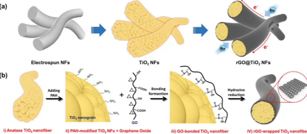
Schematic illustration of the electrospinning and graphene-wrapping process. Figure 1 shows the processing steps for the synthesis of the reduced graphene-oxide-wrapped TiO2 NFs
(here-after, rGO@TiO2 NFs). The rGO@TiO2 NFs were obtained by several synthetic steps, and the products
in each step are shown in Fig. 1a. First, as-spun Ti precursor/polymer composite NFs were obtained via an electrospinning method. After high-temperature calcination, the TiO2 NFs were formed by the
thermal decomposition of the matrix polymer and the crystallization of the TiO2 particles composing
Figure 1. Synthesis of graphene-TiO2 NFs. (a) products at each synthetic step: as-spun NFs by
electrospinning, anatase TiO2 NFs after calcination at 500 oC for 1 h, and rGO@TiO2 NFs by
graphene-wrapping. (b) graphene-wrapping mechanism: i) the surfaces of the as-prepared anatase TiO2 NFs are
functionalized to amine groups with an aqueous PAH solution (PAH-modified TiO2 NFs), ii) the GO-TiO2
NF composite solution was formulated by adding a GO solution to a PAH-TiO2 NF solution, iii) Strong
bonding formation between GO and TiO2 NFs through cross-linking, and iv) GO reduced by hydrazine to
obtain the rGO@TiO2 NF solution. Proper centrifugation and drying followed after each step. This figure
the NFs. With regard to the graphene-wrapping method, its mechanism is illustrated in Fig. 1b. In order to provide strong electrostatic interaction between the negatively charged graphene oxide (GO) and the as-prepared TiO2 NFs above, (i) we grafted the surfaces of the TiO2 NFs by using poly (allylamine
hydrochloride) (PAH). TiO2 NFs were positively charged by -NH3+ in the solution; (ii) Subsequently,
GO sheets were added to the TiO2 NF-dispersed solution, and the solution was mechanically agitated
to ensure homogeneous mixing. GO sheets have sufficient functional groups such as carboxylic acid (-COOH) and hydroxyl (-OH) groups, which induce surface-negative charges (-COO− and -O−) in the
solution. Then, the positively charged TiO2 NFs and the negatively charged GO are self-assembled; (iii)
Crosslinking between GO and PAH arises due to ring-opening of the epoxy groups of GO as well as partial contribution of the carboxylic group, originated from the nucleophile reaction of the unpaired electrons of the amine groups28; (iv) Finally, hydrazine was added to the mixed solution including the
GO and PAH-modified TiO2 NFs to transform the GO sheets into reduced GO (rGO) sheets. This
graphene-wrapping mechanism was discussed in our previous report29. As part of the processes above,
proper centrifuging and drying were conducted.
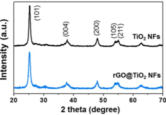
Characteristics of TiO2 NFs and rGO@TiO2 NFs. Figure 2 shows the X-ray diffraction (XRD)
patterns of the TiO2 NFs and the rGO@TiO2 NFs. The XRD patterns of both samples confirm that they
have the original anatase TiO2 structure (space group I41/amd, JCPDS PDF#21–1272). The main peak of
the anatase TiO2 at 25.2o indicates the crystal lattice plane (101), and other strong peaks at 37.8o, 48o,
54.8o, and 55o present the (004), (200), (105) and (211) planes, respectively. Moreover, it is important to
note that the graphene-wrapping process did not affect the crystal structure of the TiO2. Using the
Scherrer equation, =d w×. λΘ 0 94
cos we estimated the mean crystallite size of the nanoparticles comprising
the polycrystalline TiO2 NFs. In equation 1, d is the mean grain size, λ is the wavelength of the Cu Kα
radiation (0.154 nm), θ is the Bragg angle considered, and w is the line width at half-maximum intensity on the 2 θ scale, in radians. From this calculation, we estimated the average crystallite size of the anatase TiO2 to be 15.5 nm.
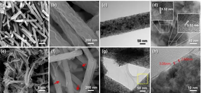
The morphological features of the TiO2 NFs and rGO@TiO2 NFs were characterized by scanning
electron microscopy (SEM) and transmission electron microscopy (TEM), respectively. As shown in the SEM images in Fig. 3a,b, calcined TiO2 NFs with a diameter of approximately 200–300 nm exhibited a
wrinkled surface and a straight line shape. The high-resolution TEM (HRTEM) image of the calcined TiO2 NFs clearly confirms that the Ti precursor was crystallized into polycrystalline TiO2, which is
composed of small nanoparticles (Fig. 3c,d). The lattice fringes of the TiO2 (3.52 Å) NF correspond to
the TiO2 (101) plane (JCPDS PDF#21–1272). Figure 3e,f depict SEM images of the rGO@TiO2 NFs. The
rGO sheets cover all the surfaces of the TiO2 NFs well and effectively interconnect the TiO2 NFs to each
other. Figure 3g exhibits a TEM image of the edge structure of the rGO@TiO2 NFs. We note the HRTEM
image in Fig. 3h, which is a highly magnified image of the yellow frame in Fig. 3g and which reveals that the thickness of the rGO sheets is approximately 3 nm.
To provide further investigation, we conducted Raman and FT-IR analyses of both the TiO2 NFs
and rGO@TiO2 NFs. The Raman spectra of the TiO2 NFs exhibit peaks which are located at
approxi-mately 145, 398, 520 and 640 cm−1 (Fig. 4). These peaks correspond to the lattice vibrational model of
the Eg(1), B1g(1), B1g(2) + A1g and Eg(3) bands of the anatase TiO2, respectively30. The Raman spectra
of the rGO@TiO2 NFs equally contain the Eg(1), B1g(1), B1g(2) + A1g and Eg(3) bands of the anatase
TiO2, which also confirms that the graphene-wrapping process does not cause any local structure
changes. Likewise, the rGO@TiO2 NFs show two peaks of rGO at 1349 and 1605 cm−1. These two
peaks denote the general G and D bands of rGO, respectively31. The Raman analysis clearly verified
that the structural properties of the TiO2 NFs, which were well covered by rGO, did not change after
the graphene-wrapping process.
Figure 5 presents the Fourier-transformed infrared (FT-IR) spectra of the TiO2 NFs, the rGO@
mode. Both the TiO2 NFs and rGO@TiO2 NFs showed Ti-O and Ti-O-Ti vibrations at 500–700 cm−132,
which provides evidence of the structural identity of these two materials. Furthermore, several bands located at a similar wavenumber in both the rGO@TiO2 NFs and the GO in H2O revealed that the
graphene-wrapping process was successful. The broad band on the rGO@TiO2 NFs overlaps with the
C = O stretch of the carbonyl groups at the edges of GO at 740 cm−1. Moreover, the C = C stretch at
Figure 3. (a–b) SEM and (c–d) TEM images of TiO2 NFs; (e–f) SEM and (g–h) TEM images of rGO@TiO2
NFs. (h) shows an HRTEM image of the yellow frame in (g). Lattice of the anatase TiO2 (inset images); the
graphene connection (red arrows) and thickness of the graphene wrapping (red lines) are well shown.
Figure 4. Raman spectra of TiO2 NFs and rGO@TiO2 NFs.
1630 cm−1 and the bending vibration O-H stretch at 3100–3500 cm−1 are apparent in both the rGO@
TiO2 NFs and the GO in H2O31.
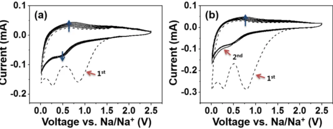
Electrochemical reaction with Na+. Figure 6a,b show the cyclic voltammetry (CV) curves of the
TiO2 NFs and the rGO@TiO2 NFs. A CV test was performed at a scan rate of 0.5 mV s−1 at 0.01 ~ 2.5 V
for six cycles.
In the first cathodic scan of the TiO2 NFs and the rGO@TiO2 NFs, first irreversible reduction peaks at
approximately 0.84 V are assigned to the formation of a solid electrolyte interface (SEI), and the second reduction peaks and the third peaks near 0.26 V and 0.02 V are attributed to sodiation and electrolyte decomposition. With subsequent cyclic sweeps, for both the TiO2 NFs and the rGO@TiO2 NFs, the
second cathodic peaks and anodic peaks shift to higher potentials (~0.5 V and ~ 0.75 V). These phenom-ena may be caused by redox couple of Ti4+/Ti3+. Such results were already observed in previous study
reported by Wu et al.33 Upon further cathodic and anodic voltage sweeps, broad cathodic and anodic
peaks near 0.5 V and 0.75 V were reversely observed in both electrodes. This result reveals that both anode materials present the same electrochemical characteristics, especially in terms of reversibility.
Discussion
Ex-situ analysis of a plausible reaction mechanism. The charge-discharge voltage curves of the
electrodes using TiO2 NFs and rGO@TiO2 NFs at a 1C rate (335 mAh g−1) were measured after one
cycle at 10 mA g-1 (Supplementary Figures S1a,b). During the first cycle at 10 mA g−1, the voltage curves
of the two electrodes showed two plateau regions near 1.25 V and 0.2 V while discharging. These two plateau regions are ascribed to the formation of a SEI layer, which is in good agreement with the results of the initial CV curves in Fig. 6. In the 1st, 2nd, 100th, and 200th cycle during the following 1C rate
charge/discharge, most of the capacities of the TiO2 NFs and rGO@TiO2 NFs are below 0.6 V vs. Na/Na+
(Fig. 7a,b). The rGO@TiO2 NFs showed enhanced capacity levels at all cycles and greatly improved
capacity retention as compared to the TiO2 NFs after 200 cycles; these results were 90% and 58% in the
rGO@TiO2 NFs and TiO2 NFs, respectively. From the voltage profiles, we found that no voltage plateau
appears in any of the cycles, which differs from the reported voltage profile of anatase TiO2 for LIBs34.
Figure 6. Cyclic voltammetry of (a) TiO2 NFs and (b) rGO@TiO2 NFs tested at a scan rate of 0.5 mV s
for six cycles.
In typical anatase TiO2, the redox potential for Li+ insertion/deinsertion is about 1.6 V versus Li/Li+;
this can be written as follows: TiO2 + xLi+ + xe− ↔ LixTiO2
In this regard, we studied the charge/discharge behaviors using TiO2 NFs and rGO@TiO2 NFs as
anodes for LIBs to determine whether the smooth voltage profiles are caused by our choice of materials. The experiment using lithium metal as a counter electrode was performed at 1C rate after pre-cycling at 10 mA g−1 (Supplementary Figure S2). In this experiment, both the TiO
2 NFs and rGO@TiO2 NFs
exhibited a Li+ ion insertion plateau near 1.6 V, as reported previously35. This finding verifies that the
reaction mechanism of TiO2 NFs and rGO@TiO2 NFs for lithium insertion is based on insertion, as
predicted. However, in the sodium insertion case, the TiO2 NFs and rGO@TiO2 NFs indicate smooth
charge/discharge voltage behaviors, which is fundamentally different from the case of lithium insertion. Although the effect of the particle size could cause some difference in the plateau length, generally the size effect does not eliminate this plateau. Therefore, it is important to note that the reaction mechanism of TiO2 for NIBs may differ from that of LIBs.
To confirm the plausible reaction mechanism of anatase TiO2 for sodium insertion/extraction, we
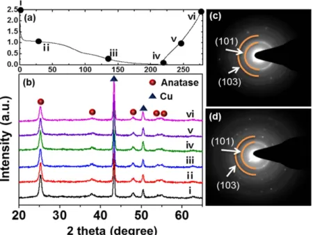
performed ex-situ XRD and ex-situ TEM analyses. Figure 8a presents the first cycle voltage profile at a 0.2C rate. Each Roman numeral indicates the cut-off voltage for the ex-situ analyses. Figure 8b shows
ex-situ XRD patterns of pristine TiO2 NFs at 1 V, 0.1 V and 0.01 V while discharging and at 0.1 V and
2.5 V while charging. We could not find any significant structural decomposition through the ex-situ XRD analysis, and thus this may be interpreted as that the anatase structure was maintained during cycling. An ex-situ TEM analysis was performed to determine the structural stability. Figure 8c,d indi-cate selected-area electron diffraction (SAED) patterns in fully discharged and fully charged states, respectively. Our results rather coincide with a recent report by Kim et al.36 Kim reported that the
anatase structure is maintained during extensive cycling and suggested that the reaction mechanism is insertion through an X-ray absorption spectroscopy (XAS) analysis. This may differ from the results reported by Wu et al., who claimed that the XRD reflections of the anatase phase disappear in the discharged state. Although we observed that the (004) and (200) reflections at 38o and 48o still exist
after a full discharge in our case, the results in here remain controversial. Therefore, a further elaborate analysis is necessary for a precise investigation of the reaction mechanism of graphene/TiO2 hybrid
materials.
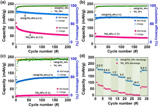
Electrochemical performances. The galvanostatic cycles of Na-anode electrodes using TiO2 NFs
and rGO@TiO2 NFs were tested at rates of 0.2C (67 mA g−1), 1C (335 mA g−1) and 5C (1.675 A g−1)
for 200 cycles (Fig. 9a–c). All cycle tests were performed after an initial charge/discharge process at 10 mA g−1. During the galvanostatic cycles, the rGO@TiO
2 NFs maintained significantly higher specific
Figure 8. (a) First cycle voltage profile (X axis-specific capacity/Y axis-potential); (b) Ex-situ XRD data
(Discharge; pristine, 1 V, 0.1 V, fully discharged. Charge; 1 V, fully charged) and SAED pattern with a TEM images in (c) fully discharged and (d) fully charged states.
capacities than those of the TiO2 NFs. For example, at the rates of 0.2C, 1C, and 5C, the rGO@TiO2
NFs exhibits initial discharge capacities of 217, 165 and 124 mAh g−1, respectively. Previously, Cha et al. showed through cyclic voltammetry that sodium ions could be stored in graphene21. In other
words, graphene could serve as an electrochemically active material. However, in this study, we found through an elemental analysis (EA) that the detected carbon element in rGO@TiO2 NFs was only 1.85
wt% (Supporting Information, Table S1). This negligible amount of carbon coming from graphene sheets may not appreciably contribute to the capacity of a cell. The rGO@TiO2 NFs show very stable
cycle lifetimes with high coulombic efficiency (> 98%). They show high capacity retention of about 90% after 200 cycles at 1C. Moreover, at 5C, the cycling capacities of the rGO@TiO2 NFs increase for
about 70 cycles, which indicates a gradual improvement of the electrode kinetics or an increase in the active area. However, the TiO2 NFs show a considerably low initial discharge capacity of 131 mAh g−1
at 0.2C. Unfortunately, at higher rates, although this 1D nanostructured TiO2 may make it possible
effectively to transport Na+ with regard to the diffusion length, the original insulating property of
the TiO2 NFs markedly limited the electron transport (47 mAh g−1 at a 1C rate and 12 mAh g−1 at
a 5C rate). For a comparison of the TiO2 NFs and rGO@TiO2 NFs in light of the power density, the
rate performances are shown in Fig. 9d. The rGO@TiO2 NFs exhibited high reversible capacities of
217, 182, 164, 146, 119, 87 and 197 mAh g−1, while the TiO
2 NFs showed reversible capacities of 101,
56, 36, 21, 8, 2 and 68 mAh g−1 at rates of 0.2C, 0.5C, 1C, 2C, 5C, 10C and recovering rate of 0.2C,
respectively. The rGO@TiO2 NFs showed 91% of initial capacity at 0.2C when the current density was
reversed back to 0.2C, whereas the TiO2 NFs exhibited 67% of initial capacity under same condition.
The rGO@TiO2 NFs clearly show significantly improved rate performances compared to those of the
TiO2 NFs at all rates. The higher reversible capacities and better cycle performances are evidences
that wrapped graphene sheets significantly increase the electrical conduction of TiO2 NFs and offer
higher electrode conductivity levels with their three-dimensionally interconnecting nanofibers in a complementary manner.
In summary, TiO2 NFs with a wrinkled surface and a uniform diameter (200–300 nm) were
syn-thesized via an electrospinning method. To improve the electrical conductivity of the TiO2 NFs, rGO
sheets were effectively wrapped onto PAH-grafted TiO2 NFs. We verified that the sodiation mechanism
is clearly based on an insertion process by conducting ex-situ XRD and ex-situ TEM analyses. The Na anode electrode with rGO@TiO2 NFs delivered a high reversible capacity of 217 mAh g−1 at 0.2C,
excel-lent cycle performance at 1C (90% capacity retention during 200 cycles) and superior rate capability of 124 mAh g−1 at a 5C rate (1.675 A g−1). The graphene-wrapping assisted by the surface grafting of the
TiO2 NFs offers a versatile way to improve the electrical conductivity and electrochemical stability of
TiO2 NFs for application to Na ion batteries.
Figure 9. Charge–discharge capacity and coulombic efficiency vs. the cycle number for TiO2 NFs and rGO@
TiO2 NFs tested (a) at a rate of 0.2C (67 mA g−1), (b) at a rate of 1C (335 mA g−1) and (c) at a rate of 5C
(1675 mA g−1). (d) Rate capabilities of TiO
2 NFs and rGO@TiO2 NFs evaluated at various rates of 0.2C,
needle was used in the electrospinning condition. Finally, to decompose the matrix polymers and obtain TiO2 NFs, the collected as-spun nanofibers were heat-treated at 500 oC for 1 h to decompose the matrix
polymer and crystallize the TiO2 NFs.
PAH functionalization and graphene-wrapping. rGO@TiO2 NFs were synthesized by the
follow-ing three methods. First, 1 g of PAH was dissolved into 25 ml of DI water, and an amount of 0.13 g of TiO2 NFs was added to this aqueous solution. This solution was mildly stirred for 1 h to functionalize
the surface of the TiO2 NFs homogeneously into an amine end group. Then, centrifuging, washing and
vacuum drying at 80 oC for 6 h followed. Second, an amount of 0.11 g of prepared PAH-TiO
2 NFs was
dispersed in 10 ml of DI water, and 3200 μ L of aqueous GO solution was added to this mixture to synthe-size GO-coated TiO2 NFs as a hybrid anode material. Third, the GO-wrapped TiO2 NFs were dispersed
in 10 ml of DI water, and 1.5 g of hydrazine monohydrate was added to this solution to obtain rGO@ TiO2 NFs by reducing GO to rGO.
Material characterization. The anatase structure of TiO2 was investigated by X-ray diffraction
(XRD, D/MAX-RB (12KW) and D/MAX-RC (12 kW), Rigaku). The morphologies of the TiO2 NFs and
rGO@TiO2 NFs were observed by a scanning electron microscope (SEM, Philips). The lattice fringe
and selected-area electron diffraction (SAED) patterns were obtained by a transmission electron micro-scope (TEM, Tecnai F30 S-Twin, FEI). Raman spectroscopy was carried out using a LabRAM HR UV/ Vis/NIR PL device by Horiba Jobin Yvon, France. The Fourier-transform infrared spectroscopy (FT-IR) analysis was performed using the attenuated total reflection (ATR) method for the GO solution and the KBr-pellet method for the TiO2 NFs and the rGO@TiO2 NFs in transmission mode on an IFS66V/S &
Hyperion 3000, Bruker Optiks, Germany. Carbon contents were measured by an element analysis (EA, Flash 2000 series, Thermo Scientific).
Electrochemical measurements. The composition of the slurries was 75 wt% active materials, 15 wt% Super P, and 10 wt% polyvinylidene fluoride (PVDF) binder dissolved in N-methyl-2-pyrrolidinone (NMP). The loading of the active material was about 0.85 mg cm−2. Using a doctor blade technique, the
slurry was coated onto Cu foils to a thickness of 90 μ m. Then, overnight vacuum drying at 80 oC followed.
Celgard 2032 coin cells were used to assemble half-cells in an argon-filled glove box. To assemble the half-cells of NIBs, Na foils were used as the counter electrodes. Glass microfiber filters (Whatman) were used as the separator. The electrolyte was 1 M of NaClO4 in PC including 5 wt% of fluoroethylene
car-bonate (FEC). To prepare the half-cells for the LIBs, Li foils and Celgard 2400 were used as counter elec-trodes and as a separator, respectively. The electrolyte was 1 M LiPF6 in EC/DEC (1:1 v/v). Cell tests were
carried out with a Maccor 4000 battery tester at a voltage window of 0.01 V ~ 2.5 V. Cyclic voltammetry (CV) was performed on a WBCS3000 device by WonATech at a scan rate of 0.5 mV s−1 at 0.01 V ~ 2.5 V.
References
1. Palomares, V., Casas-Cabanas, M., Castillo-Martínez, E., Han, M. H. & Rojo, T. Update on Na-based battery materials. A growing research path. Energy Environ. Sci. 6, 2312–2337 (2013).
2. Slater, M. D., Kim, D., Lee, E. & Johnson, C. S. Sodium-Ion Batteries. Adv. Funct. Mater. 23, 947–958 (2013).
3. Yabuuchi, N., Kubota, K., Dahbi, M. & Komaba, S. Research Development on Sodium-Ion Batteries. Chem. Rev. 114, 11636− 11682 (2014).
4. Ponrouch, A., Marchante, E., Courty, M., Tarascon, J.-M. & Palacín, M. R. In search of an optimized electrolyte for Na-ion batteries. Energy Environ. Sci. 5, 8572–8583 (2012).
5. Han, X., Li, T. & Hu, L. Tin Anode for Sodium-Ion Batteries Using Natural Wood Fiber as a Mechanical Buffer and Electrolyte Reservoir. Nano Lett. 13, 3093–3100 (2013).
6. Wang, J. W., Liu, X. H., Mao, S. X. & Huang, J. Y. Microstructural Evolution of Tin Nanoparticles during In Situ Sodium Insertion and Extraction. Nano Lett. 12, 5897–5902 (2012).
7. Darwiche, A. et al. Better Cycling Performances of Bulk Sb in Na-Ion Batteries Compared to Li-Ion Systems: An Unexpected Electrochemical Mechanism. J. Am. Chem. Soc. 134, 20805–20811 (2012).
8. Kim, Y. et al. An Amorphous Red Phosphorus/Carbon Composite as a Promising Anode Material for Sodium Ion Batteries. Adv.
Mater. 25, 3045–3049 (2013).
9. Li, W. et al. Sn4+xP3@amorphous Sn-P composites as anodes for sodium-ion batteries with low cost, high capacity, long life, and
superior rate capability. Adv. Mater. 26, 4037–4042 (2014).
10. Dahbi, M., Yabuuchi, N., Kubota, K., Tokiwa, K. & Komaba, S. Negative electrodes for Na-ion batteries. Phys. Chem. Chem. Phys. 16, 15007–15028 (2014).
21. Cha, H. A., Jeong, H. M. & Kang, J. K. Nitrogen-doped open pore channeled graphene facilitating electrochemical performance of TiO2 nanoparticles as an anode material for sodium ion batteries. J. Mater. Chem. A 2, 5182–5186 (2014).
22. Ding, S. et al. Graphene-supported anatase TiO2 nanosheets for fast lithium storage. Chem. Commun. 47, 5780–5782 (2011).
23. Yang, S., Feng, X. & Müllen, K. Sandwich-Like, Graphene-Based Titania Nanosheets with High Surface Area for Fast Lithium Storage. Adv. Mater. 23, 3575–3579 (2011).
24. Qiu, Y. et al. Synthesis of Size-Tunable Anatase TiO2 Nanospindles and their Assembly into Anatase@Titanium Oxynitride/
Titanium Nitride-Graphene Nanocomposites for Rechargeable Lithium Ion Batteries with High Cycling Performance. ACS Nano 4, 6515–6526 (2010).
25. Li, N. et al. Battery Performance and Photocatalytic Activity of Mesoporous Anatase TiO2 Nanospheres/Graphene Composites
by Template-Free Self-Assembly. Adv. Funct. Mater. 21, 1717–1722 (2011).
26. Chen, J. S., Wang, Z., Dong, X. C., Chen, P. & Lou, X. W. D. Graphene-wrapped TiO2 hollow structures with enhanced lithium
storage capabilities. Nanoscale 3, 2158–2161 (2011).
27. Bruce, P. G., Scrosati, B. & Tarascon, J.-M. Nanomaterials for Rechargeable Lithium Batteries. Angew. Chem. Int. Ed. Engl. 47, 2930–2946 (2008).
28. Satti, A., Larpent, P. & Gun’Ko, Y. Improvement of mechanical properties of graphene oxide/poly(allylamine) composites by chemical crosslinking. Carbon 48, 3376–3381 (2010).
29. Shin, J., Park, K., Ryu, W.-H., Jung, J.-W. & Kim, I.-D. Graphene wrapping as a protective clamping layer anchored to carbon nanofibers encapsulating Si nanoparticles for a Li-ion battery anode. Nanoscale 6, 12718–12726 (2014).
30. Zhang, W. F., He, Y. L., Zhang, M. S., Yin, Z. & Chen, Q. Raman scattering study on anatase TiO2 nanocrystals. J. Phys. D. Appl. Phys. 33, 912–916 (2000).
31. Guo, H.-L., Wang, X.-F., Qian, Q.-Y., Wang, F.-B. & Xia, X.-H. A Green Approach to the Synthesis of Graphene Nanosheets. ACS
Nano 3, 2653–2659 (2009).
32. Goh, G. K. L., Han, X. Q., Liew, C. P. K. & Tay, C. S. S. Crystallinity and Orientation of Solution Deposited Anatase TiO2 Films. J. Electrochem. Soc. 152, C532–C536 (2005).
33. Wu, L., Buchnolz, D., Bresser, D., Chagas, L. G. & Passerini, S. Anatase TiO2 nanoparticles for high power sodium-ion anodes. J Power Sources 251, 379–385 (2014).
34. Koudriachova, M., Harrison, N. & de Leeuw, S. Orthorhombic Distortion on Li intercalation in Anatase. Phys. Rev. B 69, 1–6 (2004). 35. Sudant, G., Baudrin, E., Larcher, D. & Tarascon, J.-M. Electrochemical lithium reactivity with nanotextured anatase-type TiO2.
J. Mater. Chem. 15, 1263–1269 (2005).
36. Kim, K. T. et al. Anatase Titania Nanorods as an Intercalation Anode Material for Rechargeable Sodium Batteries. Nano Lett. 14, 416–422 (2014).
Acknowledgements
This work was supported by a grant from the Korea CCS R&D Center (KCRC) funded by the Korean government (Ministry of Science, ICT & Future Planning) (No. NRF-2014M1A8A1049303).
Author Contributions
Y.Y. and J.W.J. contributed to conceiving the concept. Y.Y. established nearly all parts of the experimental system and carried out the measurements and characterizations, and J.W.J. assisted with some parts. Y.Y., J.W.J. and K.P. wrote the text of the entire manuscript and prepared all figures together. J.W.J. drew the Fig. 1. K.P. provided research advice, and I.D.K. oversaw the project and led the effort to completion. All authors reviewed the manuscript.
Additional Information
Supplementary information accompanies this paper at http://www.nature.com/srep Competing financial interests: The authors declare no competing financial interests.
How to cite this article: Yeo, Y. et al. Graphene-Wrapped Anatase TiO2 Nanofibers as High-Rate and
Long-Cycle-Life Anode Material for Sodium Ion Batteries. Sci. Rep. 5, 13862; doi: 10.1038/srep13862 (2015).
This work is licensed under a Creative Commons Attribution 4.0 International License. The images or other third party material in this article are included in the article’s Creative Com-mons license, unless indicated otherwise in the credit line; if the material is not included under the Creative Commons license, users will need to obtain permission from the license holder to reproduce the material. To view a copy of this license, visit http://creativecommons.org/licenses/by/4.0/