실외조명 LED용 SMPS의 가속수명시험법 제안
임성용1†․형재필1․임홍우1․오근태2
1한국기계전기전자시험연구원, 2수원대학교
Suggested Accelerated Life Test Method of SMPS for Outdoor Lighting LED
Seong-Yong Lim1†․Jae-Phill Hyong1․Hong-Woo Lim1․Geun-Tae Oh2
1Korea Testing Certification, 2Suwon University
Purpose: This study has developed the accelerated lifetime test method for smps for outdoor lighting LED through two factors of temperature and humidity.
Methods: Acceleration condition was confirmed for each stress and model, and acceleration life test model was estimated according to acceleration condition.
Results: As a result of confirming the accelerated life test model, in the case of humidity, acceleration was established only in the foreign products. Therefore, it is confirmed that the acceleration condition is insufficient. However, the estimated parameters for temperature are relatively constant. It is therefore suitable for power supply acceleration tests for outdoor lighting LEDs.
Conclusion: The SMPS acceleration test for outdoor lighting LED can improve the availability of the product by developing an accelerated life test method that guarantees the reliability of the product.
1)
Keywords: Solide State Lighting, Power Source, SMPS, ALT, Failuer mode and Failure Mechanism
1. 서 론
2014년 전반기 관급 LED 실외 조명(보안등. 가로 등, 터널등, 투광등 기구 조달 기준)의 시장은 2013년 전반기에 비해 무려 60% 이상의 고성장을 이루고 있 다. 일반적인 실외조명 시장은 연평균 성장률이 5%
미만인 것을 감안하면 상당히 이례적인 성장으로 볼 수 있다[1].
이러한 성장에 맞춰 전원 공급 장치도 외부에서 사
용이 되어야 하는데, 크기와 무게의 제한으로 인해 SMPS(switched mode power supply)가 주로 사용이 되 어 진다. 하지만 일반적인 SMPS는 온도, 습도, 부하에 취약한 면을 가지고 있다[2]. 이러한 약점은 실외 조 건에서 쉽게 노출되어 있어 이를 해결하기 위해 일반 적으로 SMPS 내부에 몰딩을 충진 하는 방법을 사용 하여 비 또는 습도를 보호하는 방수형태로 제작 된다.
SMPS는 설치 위치와 내부 몰딩으로 인해 유지보수 가 어려운 특성을 가지고 있어 단가가 비싸더라도 신
†교신저자 [email protected]
2017년 9월 1일 접수; 2017년 12월 13일 수정본 접수; 2017년 12월 14일 게재 확정.
Products Indoor Lighting SMPS Outdoor Lighting SMPS Industrial Lighting SMPS
Exposure
Environment Room temperature
Thermal shock/
High humidity/
High temperature
High temperature/
Low voltage
Design Features Cost-saving design High-end design/
Molding type design Endurance environment design
Power Consumption 10~60W 60~250W 100~300W
Table 1 Classification of SMPS according to usage environment
Fig. 1 Classification according to lighting SMPS driving method
뢰성을 확보하는 것이 중요하다[3]. 그러므로 실외 조 명 LED용 SMPS의 가속시험법 개발을 통해 제품의 신뢰성을 보증 할 가속수명시험법을 개발하여 제품 의 가용성을 높여야 한다.
본 연구는 실외 조명 LED용 SMPS에 대해 온도, 습 도 2가지 요인을 통하여 시험을 통해 실외 조명 LED 용 SMPS에 맞는 가속수명시험법을 개발하였다.
2. 조명용 SMPS의 특성 및 고장모드/메커니즘
2.1 조명용 SMPS의 종류 및 특성
최근의 조명은 대체로 LED와 OLED를 사용하는 데 이런 광원은 DC 입력을 필요로 하기 때문에 시중 에서 사용하기 위해서는 SMPS에서 AC를 DC로 바 꿔주는 기능이 요구된다. 이러한 SMPS는 크게 절연 및 구동방식, 사용 환경에 따라 다른 요구사항을 갖 게 된다.
2.1.1 절연에 따른 분류
고주파 트랜스포머의 유무에 따라 비절연현과 절 연형으로 나눌 수 있다. 비절연방식의 경우 고전압 및 누설전류의 사고 위험으로부터 사용자를 직접적인 보호를 하지 못하며 추가적인 기구상의 보호가 요구 된다. 절연형의 경우에 고전압 또는 누설전류로 인한 사고 위험으로부터 사용자를 보호하기 위해 고주파 절연 트랜스포머를 사용하게 된다. 이때 고주파 트랜 스 포머는 절연 목적 외에 권선비에 의해 출력 전압을 조절하는 역할도 한다. 절연형의 경우 고주파 트랜스 포머가 삽입되어 있다는 점을 제외하고 그 기본특성 이 비절연형과 유사하다.
2.1.2 사용 환경에 따른 분류
조명 장치와 SMPS가 설치되는 환경에 따라 실내조 명용 SMPS/실외조명용 SMPS/산업조명용 SMPS로 구분 할 수 있다. 실내조명용 SMPS의 경우 상온조건 인 환경에서 쓰이며 주로 저전력 용도로 쓰인다. 실외 조명용 SMPS인 경우 실내조명용 SMPS인 경우보다 더욱 가혹한 열충격이나 습도 환경에 노출된다. 그리 고 산업조명용 전원공급 장치는 진동, 온도, 습도, 전 압 등 산업현장에 발생하는 다양한 스트레스에 노출 된다. 각각의 SMPS는 각각의 환경에 대비하기 위해 추가적인 설계가 되어 있다.
2.2 SMPS의 기본 구조
조명용 SMPS 주로 AC 입력을 DC 출력으로 변환
Fig. 2 Principle of lighting SMPS 하는 형태이며, 안정된 동작과 수명을 유지 하기 위해
전압과 전류의 범위를 초과 하지 않게 설계되어있다.
구동회로는 대부분 고효율과 경량화를 위하여 스위칭 레큘레이터 방식(SMPS: Switched Mode Power Supply) 를 사용하고 있으며, 입력 전원을 직류로 바꾸기 위하 여 브리지 정류회로를 사용한다. 이후에 AC 입력이 전원에서 커패시터 또는 인덕터에 부하로써 인가되 면 전압과 전류의 위상 차이가 발생하여 실제 부하에 필요한 전류와 다른 전류가 흐르게 된다. 이를 보정하 는 회로를 PFC(Power Factor Correction)라 한다.
추가로 직류 입력전압을 직류 출력전압으로 변환 하는 DC-DC 컨버터, 출력 전압을 안정화 시키는 궤 환 제어 회로, 다시 출력 전압의 오차를 증폭하는 오 차 증폭기, 증폭된 오차와 삼각파를 비교하여 구동 펄 스를 생성하는 비교기, DC-DC 컨버터의 주 스위치를 구동하는 구동 회로 등으로 구성되어 있다.
2.3 SMPS의 고장모드/메커니즘
전원 공급 장치의 생길 수 있는 고장모드/고장메커 니즘은 발생 원인에 따라 세분화 할 수 있으나 가장 큰 고장으로는 미점등, 효율의 감소이다.
미점등은 주로 커패시터, 다이오드, 트랜지스터, IC 칩 불량을 통해 발생하게 되고, 효율 감소는 저항, 트 랜지스터와 커패시터 열화를 통해 발생하게 된다.
“Park et al.[2]”에서는 <Fig. 3>과 같이 주된 고장 원인 은 저항 불량으로 보고 있고 추가적인 퓨즈에 파손은 IC와, 다이오드의 고장이 생기면 회로를 보호하기 위 해 발생한다.
이러한 소자들은 전기에너지가 흐르는 구성부품으 로 주로 고속스위칭을 하는 트랜지스터의 방열설계 불량, 커패시터 전해액 누액 및 저하로 인한 리플증가 와 공진점을 변하게 한다.
Fig. 3 Failure ranking of SMPS
3. 실외조명 LED용 SMPS의 시험 설계
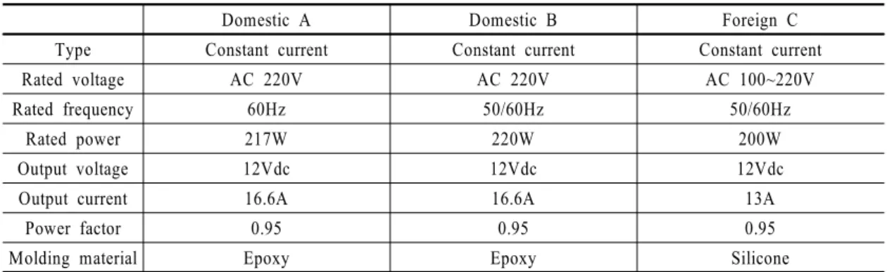
3.1 대상 SMPS 및 초기특성
본 논문에서 사용한 SMPS는 가속수명시험법 개발 을 위하여 대표성을 가지는 150W 급 제품 국산 2종과 외산 1종을 선정 하였다.
3.2 실외조명 LED용 SMPS의 FMEA, QFD 분석 필드에서 사용되는 BLDC 모터 드라이버의 고장 사례 및 모터 드라이버의 구조를 참고하여 다음 <Table 3>과 같이 FMEA 분석 하였다. FMEA 분석한 결과 필 터가 RPN 점수가 가장 높았으며, 그 뒤에 IC, 트랜스, 커패시터가 높았다.
<Table 4>는 위에 FMEA 분석 한 데이터를 이용하 여 QFD 1단계로 변환한 것이다. SMPS의 주 고장모 드는 트랜지스터 열화, IC 손상, 필터 열화, 트랜스 열 화, 커패시터 열화, 몰딩 소손으로 추정된다.
QFD 2단계는 QFD 1단계에서 분석된 고장 모드 점 수의 합계로 다음 <Table 5>와 같이 시험 내용을 결정 하였다. 그 결과 고온, 고온고습 시험이 가장 큰 영향 을 주는 고장메커니즘으로 확인하였다.
Domestic A Domestic B Foreign C
Type Constant current Constant current Constant current
Rated voltage AC 220V AC 220V AC 100~220V
Rated frequency 60Hz 50/60Hz 50/60Hz
Rated power 217W 220W 200W
Output voltage 12Vdc 12Vdc 12Vdc
Output current 16.6A 16.6A 13A
Power factor 0.95 0.95 0.95
Molding material Epoxy Epoxy Silicone
Table 2 Target SMPS and Specifications
Division
Function Failure Mode Occur-
rence Failure
Effect Seve-
rity Failure mechanism Det-
ection RPN Detection Method Sub
system Equipment
SMPS
Wire To connect I / O to the product
breaking of a wire
4 Electricity Opening due
to Over-current 3 Mechanical
stress 3 0
Verify operation
Corrosion 3 Corrosion
(contact surface) 2 Corrosion 3 18
Solder Electrical bonding between PCB and device
Fatigue 3 Opened due to solder crack
3 Temperature,
Corrosion 2 18 Visual
inspection
Degradation 4 4 Temperature 3 48
Transistor
Semiconductor device serving as amplification and
switching
Damaged 4 Damage due
to design changes or Environmental stress
3
Temperature, Humidity, Mechanical
stress
2 24 Verify
operation
Degradation 5 4 Temperature 4 80
Photodiode
Electrical isolation between inputs and outputs allows signal transmission between circuits with different potentials or impedances
Damaged 4 Damage due
to design changes or Environmental stress
3
Temperature, Humidity, Mechanical
stress
2 24 Verify
operation
Degradation 5 4 Temperature 3 60
IC A set of electronic circuits
made of semiconductors Damaged 4
Decrease in conversion efficiency, decrease in input adaptability, degradation in load
adaptability 5
Temperature, Humidity, Mechanical
stress
5 100 Verify operation
Filter Noise elimination of current Degradation 5 Damage due to design changes or Environmental stress
4 Temperature 4 80 Verify
operation
Trans
Devices for transferring electrical energy from one circuit to another through an inductive electrical conductor
Degradation 4
Damage due to design changes or Environmental stress
5 Temperature 5 100 Verify
operation
Capacitor
Devices for storage of electric potential energy in electric
circuits
Destruction 4 Time constant change, Duty ratio change Overcurrent due to increase in ripple
5
Temperature
3 60
Verify operation
Degradation 5 4 5 100
Molding
Protects the product against external environment and shocks and reduces internal
heat
Fatigue 3
Product damage due to mechanical stress
2 Temperature, Humidity, Mechanical
stress
2 12
Visual inspection
Burnout 4 4 3 48
Table 3 FMEA
Failure mechanism Cause
of failure
Transistor degradation
IC damage
Filter degradation
Trans degradation
Capacitor degradation
Molding burnout
Temperature ◎ ◎ ◎ ◎ ◎ ○
Temperature and Humidity ◎ ◎ ◎ ◎ ◎
Temperature change ○ ○
Vibration △ △ △
Shock △ △ △
Total Score 15 12 10 13 5 10
Rank 1 3 5 2 6 5
◎: 5 points, ○: 3 points, and △: 1 point. ◎ score of 5 indicates that the influence of ◎ is very large compared to other influences.
Table 4 QFD Step 1
Test Methods
Failure Modes /Mechanisms
High temperature test
Hight temperature and
high humidity test
Thermalshock
test Vibration test Impact test
Transistor degradation 15 ◎ ◎ ○ △ △
IC damage 12 ◎ ◎ △ △
Filter degradation 10 ◎ ◎
Trans degradation 13 ◎ ◎ ○
Capacitor degradation 5 ◎
Molding burnout 10 ○ ◎ △ △
Total score 305 300 84 37 37
Rank 1 2 3 5 5
◎: 5 points, ○: 3 points, and △: 1 point. ◎ score of 5 indicates that the influence of ◎ is very large compared to other influences.
Table 5 QFD Step 2
Stress Level Temperature Humidity Operating condition Number of samples
Level 01 85℃ - 220V
1.0Ω Load Same condition as actual
load(Output 12V, 12A)
15 (5 per company)
Level 02 110℃ - 15 (5 per company)
Level 03 85℃ 50% 15 (5 per company)
Level 04 85℃ 90% 15 (5 per company)
Table 6 Stress factor and level design 3.3 실외조명 LED용 SMPS의 스트레스 인자 및
레벨 설계
본 논문에서는 앞서 실시한 FMEA, QFD를 참고하 여 고온 시험과 고온 고습 시험을 진행하였다. 온도
는 예비 시험을 통해 제품의 특성이 유지되는 120 ℃ 를 기준으로 각 제품별 편차치를 고려해 시험 최대 온 도를 약 110℃로 정하였다.
이는 <Table 6>에서 확인할 수 있으며, 각 레벨에 서는 회사별로 5개의 시료를 사용하였다.
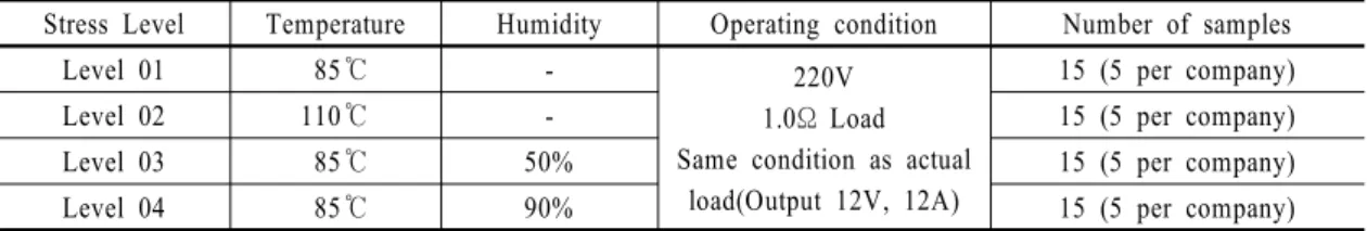
Acceleration
condition Company 85℃ 110℃
Sample Result Time Sample Result Time
High temperature operation test
Domestic A
#16 F 1,900 #01 F 600
#17 C 1,900 #02 F 450
#18 F 1,400 #03 F 450
#19 F 1,600 #04 F 600
#20 F 1,600 #05 F 450
Domestic B
#16 C 1,900 #01 F 500
#17 C 1,900 #02 F 800
#18 F 1,900 #03 F 350
#19 C 1,900 #04 F 650
#20 F 1,600 #05 F 950
Foreign C
#16 F 1,900 #01 F 600
#17 F 1,900 #02 F 750
#18 F 1,400 #03 F 300
#19 C 1,900 #04 F 300
#20 C 1,900 #05 F 600
F: Failure, C: Censored
Table 7 Test result in high temperature and high humidity operation test
Fig. 4 Change in efficiency over time (High-temperature operation test)
4. 실외조명용 SMPS의 시험 결과
4.1 고온 동작 시험 결과
고온동작 시험 결과 제품의 열화로 인한 효율 감소 를 보이지 않았으나 제품 작동에 문제가 발생하였다.
이에 수명 산출은 제품의 생존 여부에 맞춰서 수명 산
출을 하였다.
4.1.1 고온 동작 시험 데이터
고온 시험 결과 85℃ 조건은 총 1,900시간까지 진행 하였고, 110℃ 조건에서는 시료가 모두 고장이 발생한 950시간까지 시험을 진행하였다. <Fig. 4>에서 제품의 효율을 확인한 결과 제품의 열화를 확인 하지 못하였다.
Company Division Chi- square
Degree of freedom (DF)
P Value
Validity for Acceleration Domestic A Test for the same shape parameter 0.0246267 1 0.875
Accepted Test for the same scale parameter 190.684 1 0.000
Domestic B Test for the same shape parameter 2.79250 1 0.095
Accepted Test for the same scale parameter 44.5663 1 0.000
Foreign C Test for the same shape parameter 2.93989 1 0.086
Accepted Test for the same scale parameter 61.9252 1 0.000
Table 8 Acceleration verification result(High-temperature operation test)
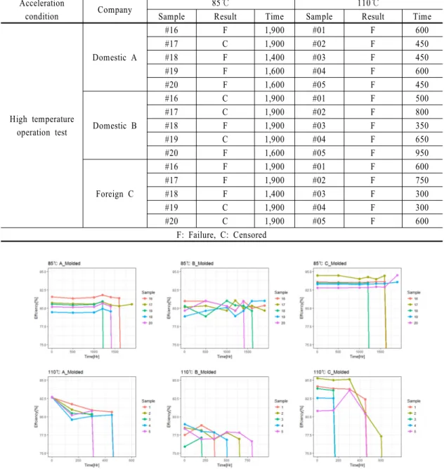
Fig. 5 Probability over time(High-temperature operation test)
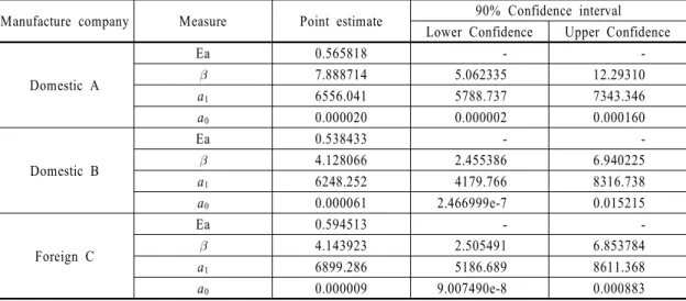
Manufacture company Measure Point estimate 90% Confidence interval Lower Confidence Upper Confidence
Domestic A
Ea 0.565818 - -
7.888714 5.062335 12.29310
a1 6556.041 5788.737 7343.346
a0 0.000020 0.000002 0.000160
Domestic B
Ea 0.538433 - -
4.128066 2.455386 6.940225
a1 6248.252 4179.766 8316.738
a0 0.000061 2.466999e-7 0.015215
Foreign C
Ea 0.594513 - -
4.143923 2.505491 6.853784
a1 6899.286 5186.689 8611.368
a0 0.000009 9.007490e-8 0.000883
Table 9 Point estimation and confidence intervals for parameters of accelerated life test model 4.1.2 가속 수명 시험 데이터 분석
앞서 실시한 고온 동작 시험에서 두 조건 85 ℃, 110
℃에서 모두 고장이 발생했기 때문에 모델식을 이용 하여 신뢰성 수준을 추정하였다. 가속 추정 전 형상모 수와 척도모수를 통한 가속성 성립 여부를 검정 한 결 과 <Table 8>과 <Fig. 5>와 같이 SMPS 3모델 모두 가 속성 성립이 되는 것으로 확인 하였다.
온도에 의한 가속수명시험의 경우 화학반응에 의한 열화고장을 모형화 하는 아레니우스 관계(Arrhenius re-
lationship)가 수명-스트레스 관계식으로 가장 널리 적용 된다. 여기서 온도에 의하여 가속되는 수명분포의 모수를
라 할 때, 아레니우스 관계는 다음과 같이 표현된다.
∙
여기서, 는 활성화 에너지(activation energy, 단위: eV),
× 는 볼츠만 상수, 는 절대온도 (섭씨 온도 + 273.16), 는 재료 물성과 시험조건에 따른 상수이다.
Manufacture
company Arrhenius model relation Domestic A
Domestic B
Foreign C
Table 10 Arrhenius model relation
Manufacture
company Acceleration factor Domestic A
Domestic B
Foreign C
Table 11 Acceleration factor estimate throughaccelerated life test model
Manufacture
company Measure Point estimate
90% Confidence interval Lower Confidence
Upper Confidence
Domestic A
24,168 15,461 37,779
26,477 17,088 41,025 MTTF 31,906 20,730 49,108
Domestic B
19,076 6,402 56,838
22,710 7,486 68,900 MTTF 32,435 10,087 104,293
Foreign C
23,007 9,232 57,339
27,372 10,959 68,364 MTTF 39,040 15,171 100,464 Table 12 Life expectancy through accelerated
life test model
<Table 9>는 가속수명시험모델의 모수에 대한 점 추정치와 신뢰구간이다. 여기서 Ea는 활성화 계수, 는 형상 모수, a0, a1은 시험 조건에 따른 상수이다.
위의 모수를 통해 각 제조회사별로 <Table 10>과 같은 아레니우스 모델 관계식을 도출할 수 있다.
4.1.3 가속계수 및 수명추정
가속계수는 일반선형모델에서 추정된 모수 중
를 제외한 값이라고 할 수 있다. 사용온도를 , 가속 온도를 라 하면, <Table 10>에서 추정된 모델식을 이용하여 가속계수를 <Table 11>로 표현 할 수 있다.
위에서 계산한 모델식을 이용하여 사용온도 35℃
의 수명을 추정하면 <Table 12>와 같이 수명 추정치 가 계산된다.
4.2 고온 고습 동작 시험 결과
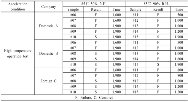
고온 고습 동작 시험 결과 제품의 열화로 인한 고장 은 보이지 않았으나 제품의 작동이 안 되는 경우가 발 생하였다. 이에 수명 산출은 제품의 생존 여부에 맞춰 서 수명 산출을 하였다.
4.2.1 고온 고습 동작 시험 데이터
고온 고습 동작 시험 결과 두 조건 모두 1,900시간 까지 진행하였다. <Fig. 6>에서 제품의 효율을 확인한 결과 제품의 열화를 확인 하지 못하였다.
4.2.2 가속 수명 시험 데이터 분석
고온 고습 동작 시험에서 진행하였던 두 조건 85℃
50% R.H, 85℃ 90% R.H에서 고장이 발생했기 때문에 모델식을 이용하여 신뢰성 수준을 추정하였다. 가속 추정 전 형상모수와 척도모수를 통한 가속성 성립 여 부를 검정 한 결과 <Table 14>와 <Fig. 7>과 같이 에폭 시로 몰딩된 제품 국산 A, 국산 B 에서는 가속성 여부 가 성립되지 않았지만, 실리콘으로 몰딩된 외산 C 모 델에서는 가속성 여부가 성립되었다.
온습도 가속수명시험은 주로 펙(Peck) 모델이 수명 -스트레스 관계식으로 가장 널리 사용된다. 온습도에 의하여 가속되는 수명분포의 모수를 라 할 때, 펙 모델은 다음과 같이 표현된다.
여기서, 는 활성화 에너지(activation energy, 단위: eV),
은 역승(Inverse Power) 모델의 추정치,
× 는 볼츠만 상수, 는 절대온도 (섭씨온도 + 273.16), 는 상대습도, 는 재료 물성과 시험조건에 따른 상수이다.
여기서 외산 C의 고온 고습 동작 시험에서 펙 모델을 통해서 확인된 값을 적용하고 은 습도수명데이터 를 참조하여 역승모델을 이용하여 확인한 결과이다.
Acceleration
condition Company 85℃ 50% R.H. 85℃ 90% R.H.
Sample Result Time Sample Result Time
High temperature operation test
Domestic A
#06 F 1,600 #11 F 500
#07 F 1,600 #12 F 1,000
#08 F 1,900 #13 F 1,000
#09 F 1,900 #14 F 1,200
#10 S 1,900 #15 S 1,900
Domestic B
#06 F 1,600 #11 F 500
#07 F 1,900 #12 F 1,000
#08 S 1,900 #13 F 1,000
#09 S 1,900 #14 F 1,600
#10 S 1,900 #15 S 1,900
Foreign C
#06 F 1,600 #11 F 800
#07 F 1,900 #12 F 800
#08 S 1,900 #13 F 1,000
#09 S 1,900 #14 F 1,200
#10 S 1,900 #15 F 1,200
F: Failure, C: Censored
Table 13 Test result in high temperature and high humidity operation test
Fig. 6 Change in efficiency over time(High temperature and high humidity operation test)
Company Division Chi-
square
Degree of freedom (DF)
P Value
Validity for Acceleration Domestic A Test for the same shape parameter 7.78144 1 0.005
Rejected Test for the same scale parameter 1.48777 1 0.223
Domestic B Test for the same shape parameter 4.96619 1 0.026
Rejected Test for the same scale parameter 1.77718 1 0.182
Foreign C Test for the same shape parameter 0.697841 1 0.404
Accepted Test for the same scale parameter 38.3387 1 0.000
Table 14 Acceleration Verification Result(High temperature and high humidity operation test)
Fig. 7 Probability over time(High temperature and high humidity operation test)
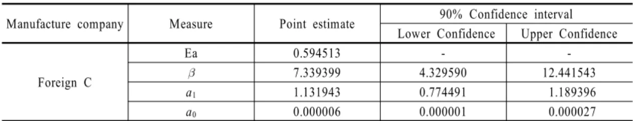
Manufacture company Measure Point estimate 90% Confidence interval Lower Confidence Upper Confidence
Foreign C
Ea 0.594513 - -
7.339399 4.329590 12.441543
a1 1.131943 0.774491 1.189396
a0 0.000006 0.000001 0.000027
Table 15 The point estimates and confidence intervals for the parameters of the accelerated life test model
Manufacture
company Peck model relation Foreign C
Table 16 Peck model relation
Manufacture
company Acceleration factor
Foreign C
Table 17 Acceleration factor estimate through accelerated life test model
Manufacture
company Measure Point estimate
90% Confidence interval Lower Confidence
Upper Confidence
Foreign C
26,051 19,205 34,014
28,717 23,060 35,815 MTTF 35,094 30,699 40,175 Table 18 Life expectancy through accelerated
life test model <Table 15>는 가속수명시험모델의 모수에 대한 점
추정치와 신뢰구간이다. 여기서 Ea는 활성화 계수, 는 형상 모수, a0, a1은 시험 조건에 따른 상수이다.
위의 모수를 통해 각 모델별로 <Table 16>과 같은 펙 모델 관계식을 도출할 수 있다.
4.2.3 가속계수 및 수명추정
가속계수는 일반선형모델에서 추정된 모수 중 를 제외한 값이라고 할 수 있다. 온도를 T, 습도를 H, 사용 조건을 , 가속조건을 로 할 경우 <Table 16>에서 추정된 모델식을 이용하여 가속계수를 <Table 17>로 표현 할 수 있다.
가속수명시험모델로부터 형상모수 는 7.339399, 활성화 에너지 Ea 는 0.594513로 계산된다.
외산 C 몰딩 SMPS의 사용조건 온도 35℃, 60% R.H 에서 위에서 계산한 모델식을 이용하여 , , MTTF 의 점추정치와 90% 신뢰구간을 추정하면 <Table 18>과 같다.
4.3 가속시험법 제안
실외 조명 LED용 전원공급 장치의 가속 수명 시험 법을 위해 2가지 스트레스 요인(온도, 습도)를 고려하 여 시험을 수행한 결과 온도에 의한 가속 수명 시험이 가장 적합한 것으로 확인된다. 고온 조건에서는 몰딩
Item Proposal formula
Lifetime - Stress Relation
Where a is constant that can be determined through an accelerated test.
is the range derived from the acceleration test. ( = 0.538~0.595)
is the Boltzmann constant. ( = × )
Acceleration factor
Where is the range derived from the acceleration test.
( = 0.538~0.595)
is the temperature you want to guarantee. (Ex. 35 ℃)
is the acceleration test progress temperature. (Ex. 85 ℃)
is the Boltzmann constant. ( = × ) Table 19 Suggested accelerated life test method
재질에 의한 영향을 확인할 수 없었으나, 습도 조건에 서는 몰딩 재질에 따라 가속 여부가 결정 되었다. 이 에 몰딩 재질 및 첨가제 종류에 따른 습도 시험이 추 가적으로 필요하다.
실외 조명 LED용 SMPS는 모든 제품이 몰딩 후 판 매가 되고 있는 시점이므로 몰딩제품에 대해 일관되게 적용할 수 있는 가속시험법을 제안하는 것이 바람직 하다. 한 모델에서만 가속성립이 된 습도를 제외하고 모든 조건에서 성립된 온도를 이용한 수명-스트레스 관계식, 가속계수를 <Table 19>로 제안한다. 각각의 식들은 3가지 제품(국산 A, 국산 B, 외산 C)에 대해서 통합된 가속시험법을 추정 파라메터의 범위를 포함 하였다.
5. 결 론
본 연구는 실외 조명 LED용 SMPS에 대해 온도, 습 도 2가지 요인을 통하여 시험을 통해 실외 조명 LED 용 SMPS에 맞는 가속수명시험법을 개발하였다.
시험결과, 실외 조명 LED용 SMPS는 온도 조건에서 는 3모델 모두 가속성이 성립하였고, 습도 조건에서는 외산 모델만 가속성이 성립하였다. 이러한 가속성 성립 여부에 따라 가속수명시험모델을 추정하였다.
우선 아레니우스 모델을 사용하여 온도의 가속수 명 시험 모델을 얻었으며, 각 모델에 따른 수명차이는
있지만 시험을 통해 얻은 모수가 비교적 일정하여 실 외조명용 SMPS 가속시험 제안법에 적절하다.
습도에 대한 가속 수명 시험 모델은 펙 모델과 역승 모델을 사용 하여 얻었으며, 각 제품 중 에폭시로 몰 딩된 제품 국산 A, 국산 B에서는 가속성 여부가 성립 되지 않았지만, 실리콘으로 몰딩된 외산 C 모델에서 는 가속성 여부가 성립되었다. 이는 습도가 실외조명 용 SMPS의 가속시험 제안법에 적절하지 않지만 몰딩 성분에 따른 가속성 성립에 대한 추가적인 시험이 가 능할 것으로 추측이 된다.
References
[1] Jang, M. S. (2014). “Correlation between outdoor LED lighting reliability and urban safety”. The Korean Institute of Illuminating and electrical Installation Engineers, Vol. 28, No. 6, pp. 24-28.
[2] Park, J. S., Choi, W. S., and Kwon, J. G. (2001).
“Development of accelerated life test method of printer SMPS”. The Korean Reliability Society, pp. 405-411.
[3] Kim, J. M., Jo, Y. S., and Lee, K. H. (2015). “Study on Reliability Prediction and HALT verification of SMPS”.
The institute of electronics engineers of Korea, pp.
847-848.
[4] Kim, H. J. (1997). “[Special] SMPS”. The korean in- stitute of power electronics, Vol. 2, No. 3, pp. 22-30.
[5] Baek, Y. H. (2009). “Eco-friendly high efficiency LED lighting development direction”. Korea Institute of Architectural Sustainable Environment and Building Systems, Vol. 3, No. 4, pp. 21-27.
[6] Hong, C. H. (2004). “New Technology Trend and Application of High Power LED”. The Korean Institute
of Illuminating and electrical Installation Engineers, Vol. 18, No. 3, p. 310.
[7] Kwon, S. H. (2015). “High power LED lighting devel- opment and technology development trend”. The Institute of Electronics Engineers of Korea, Vol. 42, No.
1, pp. 38-52.
![Fig. 1 Classification according to lighting SMPS driving method뢰성을 확보하는 것이 중요하다[3]](https://thumb-ap.123doks.com/thumbv2/123dokinfo/5507209.454568/2.808.91.721.854.1030/classification-according-lighting-driving-method뢰성을-확보하는-것이-중요하다.webp)