```
1. INTRODUCTION
The high-temperature superconducting (HTS) power device has lower weight and volume, higher efficiency as well as environment-friendly in large scale application.
The practical adaptation of the superconducting motor with low speed and high torque for large scale ship propulsion has many advantages such as high efficiency, small size and low weight due to high current density and magnetic field intensity as using the superconducting wire.
A fully HTS motor having both the field winding and the armature winding by superconducting wire is difficult to do machining due to a property of HTS wire with a thin tape shape and the cooling for making the wire into superconducting state. In previous work by other researchers, a number of the superconducting motors with HTS winding have been researched and developed. But almost all of the motors are not a fully superconducting motor because the field winding part or the armature winding part did not use a superconducting conductor.
Also, the superconducting motor has difficulties such as cooling and current lead because the field winding is located at a rotor part and rotated during operation [1]. As a motor type to get rid of moving cryogenic part which causes the difficulty of manufacture and operation, a homopolar type was proposed [2]-[6]. In this research, we present the result of manufacture and test of a homopolar motor. The homopolar motor has high temperature superconducting (HTS) armature and field coils. The armature winding of a racetrack type is locating at a stator, and the field winding generating the magnetic field is located at not a rotor but a stator portion. So, the motor has firm structure and advantage in cooling, etc. The operating frequency is supposed to be 5 Hz for low rotating speed which is needed for a purpose of ship propulsion.
* Corresponding author: [email protected]
2. DESIGN OF HOMOPOLAR MOTOR 2.1. Structure of homopolar motor
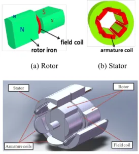
Fig. 1 is conceptual structure of rotor and stator for homopolar motor. The rotor is constructed with rotor iron and field coil. When the current flows to the field coil, the rotor iron becomes an electromagnet of a homopolar form.
That is, single pole is made in any cross section and N, S pole are made in front and back side along the rotor axis, respectively which we can know in Fig. 1(a). The field coil is fixed at gap between N and S pole, and did not rotate with rotor iron because it is structurally firm. The stator is constructed with stator iron and 6-armature coils.
(a) Rotor (b) Stator
(c) Assembled structure
Fig. 1. Conceptual structure of rotor and stator for homopolar motor.
a Woosuk University, Wanju, Korea
b Korea Polytechnic University,Siheong, Korea
c Electrical Engineering and Science Research Institute,Seoul, Korea
(Received 15 February 2013; revised or reviewed 17 March 2013; accepted 18 March 2013)
Abstract
The superconducting Homopolar motor is manufactured and tested. Homopolar motor system is simple and solid as the field coil of the motor is fixed near the stator coil without rotating system. In this paper, a 5 kW fully superconducting homopolar motor which has high temperature superconducting armature and field coils is manufactured and tested in liquid nitrogen. The critical current test results of the used 2G superconducting wire, pancake coil for rotor winding and race-track coils for armature winding are reported. Also, the test result of rotating and operating performance is presented. The operating frequency is to be 5 Hz for low-speed rotating. The developed fully superconducting Homopolar motor is the world’s first.
Keywords : Homopolar motor, superconducting motor, a fully superconducting machine, 2G HTS conductor
Progress in Superconductivity and Cryogenics
Vol.15, No.1, (2013), pp.35~39 http://dx.doi.org/10.9714/psac.2013.15.1.035
J. K. Lee*,a, S. H. Parkb, Y. Kimb, S. Leeb, H. G. Joob, W. S. Kimb, K. Choib, and S. Y. Hahnc
Test results of a 5 kW fully superconducting homopolar motor
Fig. 2. Structure of HTS conductor.
TABLEI
SPECIFICATION OF HTS CONDUCTOR.
Item Values
Bare Conductor
Width 4.0 mm
Thickness 012 mm
Cu Plating thickness
Lamination 0.02 mm
0.1 mm
Insulation Kapton tape 0.1 mm,
30 % over rapped Conductor+
including Insulation Width 4.2 mm
Thickness 0.3 mm
Critical Current 77 K, Self field 120 A
When the current applies to armature coils, a motor gets to rotate as synchronous motor. The stator winding is not designed as distributed winding of a general normal conducting synchronous motor but designed as a racetrack form of concentrated winding as in Fig. 1(b), which is proper to a 2G superconducting wire with shape as thin tape. Fig. 1(c) is the conceptual assembled structure of homopolar motor.
2.2. Specifications of HTS conductor
The 2G superconducting wire for the motor windings was supplied by SuNAM Corporation in Korea. Its cross-sectional view is shown in Fig. 2. The width of the 2G HTS coated conductor is 4.2 mm and the thickness is 0.3 mm with 0.1 mm lamination and 0.1 mm insulation.
Insulation is Kapton tape with more than 30 % over rapping in winding process. The thickness of copper stabilizer is 20 µm on both sides. The measured critical current at 77 K, self-field is 120 A. The specification of the HTS conductor is shown in Table I.
(a) front (b) back
Fig. 3. Analysis result of magnetic flux density using the finite element method for homopolar motor design at the rotation angle of 20 degrees.
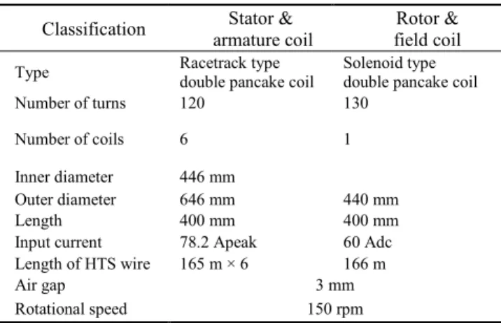
TABLEII
DESIGN SPECIFICATIONS OF THE 5 KW FULLY SUPERCONDUCTING HOMOPOLAR MOTOR.
Classification Stator &
armature coil Rotor &
field coil
Type Racetrack type
double pancake coil Solenoid type double pancake coil
Number of turns 120 130
Number of coils 6 1
Inner diameter 446 mm
Outer diameter 646 mm 440 mm
Length 400 mm 400 mm
Input current 78.2 Apeak 60 Adc
Length of HTS wire 165 m × 6 166 m
Air gap 3 mm
Rotational speed 150 rpm
2.3. Design of the 5 kW fully superconducting homopolar motor
Fig. 3 shows the analysis results of magnetic flux density, magnetic field by the finite element method for the homopolar motor design at the rotation angle of 20 degrees.
Fig. 3(a) shows the magnetic flux density of front. Fig. 3(b) shows the magnetic flux density of back. The specification of the 5 kW fully superconducting homopolar motor is shown in Table II. The number of turns of the armature windings is 120 turns (60 turns × 2) per coil, which is the double pancake coil of the racetrack shape. The number of coils is 6. The field winding is double pancake coil of the solenoid shape which has 130 turns (65 turns × 2).
It is located between two poles of rotor and does not rotate. The operating currents are 78.2 Apeak for armature coil, 60 Adc for the field coil. The air-gap is 3 mm and rotating speed is 150 rpm. The total length of superconducting wire is 1.15 km.
3. MANUFACTURE OF HOMOPOLAR MOTOR 3.1. Field Winding
The manufactured field coil for the rotor is the solenoid type double pancake coil as shown is Fig. 4. The number of turns is 130 turns and total superconducting wire length used for the winding is 166m. The turns are insulated with 0.25 mm Kapton tape in 30% over rapped. Fig. 5 shows the measured critical current of the coil and the value is 80 A in DC current. It is enough for the rated operating current of 60A.
Fig. 4. Manufactured field winding.
36 Test results of a 5 kW fully superconducting homopolar motor
Fig. 5. Measured critical current of field winding.
3.2. Armature winding
The manufactured coils for the armature winding are racetrack type double pancake coil as shown in Fig. 6. The number of turns of the coil is 120(single 60 × 2) and the length of the superconducting wire used for the coil is 165 m. The length of straight-line is 400 mm and the radius of oval track is 79.3 mm. Every turn is insulated with 0.025 mm Kapton tape for 30% over rapping. Fig. 7 shows the
Fig. 6. Manufactured armature winding.
Fig. 7. Measured critical current of armature windings TABLEIII
THE MEASURED CRITICAL CURRENT OF FIELD COIL AND ARMATURE
COILS.
Classification Critical current Field coil
Armature coil A1 Armature coil B1 Armature coil C1 Armature coil A2 Armature coil B2 Armature coil C2
80 A 77 A 80 A over
77 A 80 A over 80 A over 80 A over
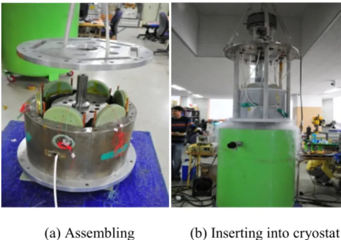
(a) Assembling (b) Inserting into cryostat Fig. 8. Experimental set-up of the fully superconducting homopolar motor.
measured critical currents of the 6-armature coils and all of the values are 77 A over. The rated current of the armature winding is 78.2 Apeak. Table III shows the critical currents of the field coil and armature coils.
3.3. 5 kW fully superconducting homopolar motor
The experimental set-up of the 5kW fully superconducting homopolar motor is progressed as shown in Fig. 8. Fig 8(a) shows assembling process. The top plate is assembling with combined rotor and stator. Fig 8(b) shows the assembled motor is inserting into cryostat.
4. TEST OF HOMOPOLAR MOTOR
Fig. 9 shows the measurement system for generator mode operation. This test is performed to check the state of field and armature coils. Commercial induction motor is installed at the top of the gearbox with built-in 150 rpm to rotate the rotor of the homopolar motor. The left side in Fig.
9 is a measurement system to detect the back e.m.f voltages of armature coils, the field coil current and the magnetic field in air-gap. The data is stored in real time using a 16CH oscilloscope. The magnetic flux densities in air-gap and straight side of armature coil are measured with cryogenic hall sensor of LakeShore Corporation.
Fig. 9. Measurement system for generator mode operation.
37
J. K. Lee, S. H. Park, Y. Kim, S. Lee, H. G. Joo, W. S. Kim, K. Choi, and S. Y. Hahn
Fig. 10. Assemble the powder brake with homopolar for load test.
Fig. 10 shows the combination homopoalr motor and powder brake for load test. The powder brake is used to give virtual load instead of real load. The powder brake is controlled by external DC current to supply the variable load by brake the rotor shaft. To measure the torque characteristic, DC current is supplied to the field coil, and 3Ø AC current is supplied to 6-armature coils by inverter.
Fig. 11 shows the result of back electromotive force for generator mode operation. The homopolar motor is driven as the generator by an induction motor with gear. The measured waveforms are not sinusoidal because of the concentrated windings.
Fig. 11. The measured results of back electromotive force in generator mode operation.
Fig. 12. The measured results of magnetic flux densities in air-gap and amarture coil.
Fig. 13. Comparison of the measured and calculated output power.
Fig. 12 shows the measured results of the magnetic flux densities in air-gap and vertical side of armature coil. A hall sensor is located at center on stator iron wall of armature coil. The other is attached at center on straight side of an armature coil. The maximum magnetic flux densities in air-gap and armature coil are about 3000 G and 300 G, respectively. Fig. 13 shows the measured torque and power driven as motor operation. The measured torque is converted to power and compared with calculated result.
The calculation is performed by 3-dimensional finite element method. The discrepancy is about 8%. We think this is caused by mechanical losses and rotation in liquid nitrogen, which is unable to consider in the calculation.
5. CONCLUSION
The homopolar motor has the benefit of simple structure without the cryogenic moving part. We manufactured and tested the 5kW fully superconducting homopolar motor using 2G HTS wire supplied by SuNAM Corporation in Korea. The critical currents of field and armature coils are measured to estimate the operating current of motor. In assembled system, we perform the operation in generator mode and motor on load. We measure the back emf, field current and magnetic flux density in generator mode to check the state of superconducting coils. On load test, we measure the output power. The measured power is 5kW and compared with the calculated result. Through this research, a fully superconducting motor using 2G HTS wire is achieved successfully.
ACKNOWLEDGMENT
This research was supported by Basic Science Research Program through the National Research Foundation of Korea(NRF) funded by the Ministry of Education, Science and Technology(2012R1A1A4A01012300).
REFERENCES
[1] X. Z. Chen,E.Q.Hu,W. J. Ge,S.D.Tang, and P.H.Wu, “The research of new electromagnetic screen system of the 300-kW
38 Test results of a 5 kW fully superconducting homopolar motor
superconducting homopolar DC machine,” IEEE Trans. Applied Superconductivity, vol. 6, pp. 77–80, 1996.
[2] B. L. Aliyevsky, B. A. Bazarnov, A. M. Oktysbrsky, N. N. Popov, A.
G. Sheratuk, and D. P. Shopen, “Superconductor homopolar machines with liquid-metal contacts,” IEEE Trans. Magnetics, vol.
28, pp. 287–290, 1992.
[3] S. H. Lee, J. P.Hong, Y. K. Kwon, and Y. S. Jo, “Study on homopolar superconducting synchronous motors for ship propulsion application,” Journal of the Korea Institute of Applied Superconductivity and Cryogenics, vol. 9, pp. 31–34, 2007.
[4] Y. K. Kwon, S. K. Baik, E. Y. Lee, J. D. Lee, J. M. Kim, Y. C. Kim, T.S. Moon, H. J. Park, W. S. Kwon, J. P. Hong, Y. S. Jo, and K. S.
Ryu, “Status of HTS motor development for industrial applications at KERI & DOOSAN,” IEEE Trans. Appl. Supercond., vol. 17, pp.
1587–1590, 2007.
[5] J.-K. Lee, S. H. Park, Y. Kim, S. Lee, W.-S Kim, K. Choi, and S.-Y Hahn, “Electrical Properties Analysis and Test Result of Windings for a Fully Superconducting 10 HP Homopolar Motor,” IEEE Trans.
Appl. Supercond., vol. 22, pp. 5201405, 2012.
[6] S. H. Park, Y. Kim, S. Lee, K. Choi, S. Hahn, and J.-K. Lee,
“Conceptual design of a 10 HP homopolar motor with superconducting windings,” The Korea Institute of Applied Superconductivity and Cryogenics, vol. 13, no. 2, pp. 9–12, May 2011.
39
J. K. Lee, S. H. Park, Y. Kim, S. Lee, H. G. Joo, W. S. Kim, K. Choi, and S. Y. Hahn