- 794 -
스파이럴 이동자 코어를 가지는 영구자석여자 횡자속 선형전동기의 등가자기회로망법을 이용한 특성해석
이지영*, 김지원*, 우병철*, 강도현*, 호앙트룽키엔**, 김광운**
한국전기연구원*, 과학기술연합대학원대학교**
Characteristic Analysis using Equivalent Magnetic Circuit Network Method for Permanent Magnet Excited Transverse Flux Linear Motor with Spiral Core in a Mover
Ji-Young Lee*, Ji-Won Kim*, Byung-Chul Woo*, Do-Hyun Kang*, Trung Kien Hoang**, and Kwang-Woon Kim**
Korea Electrotechnology Research Institute* ,University of Science & Technology**
Abstract - This paper presents an analysis method for a permanent magnet excited Transverse Flux Linear Motor (TFLM) with spiral core in a mover. The spiral core is used as mover core in order to make 3-dimensional magnetic flux path at the TFLM which has 3-dimensional magnetic flux flow. Magnetic field is analyzed by three-dimensional Equivalent Magnetic Circuit Network (EMCN) method. And an imaginary part, 'flux barrier,' is introduced to consider the spiral core characteristic. The computed thrust forces is compared to the measured results to show the effect of presented analysis method.
1. INTRODUCTION
In the factory automation system, there is a great demand for linear direct drives to avoid drawbacks of traditional drives with rotary motors and mechanical motion conversion devices such as gearbox, belt, etc. Permanent Magnets (PMs) excited Transverse Flux Linear Motors (TFLMs) have been improved in transportation and high power systems. This kind of motors promise far-reaching applications in the factory automation system and especially for linear direct drives.
PM excited TFLM has 3-dimensional flux paths. Flux path by PM is on x-z plane and flux path by winding is on y-z plane in rectangular coordinate system. This characteristic makes difficult to use general laminated core, which lamination direction is in one straight direction, in the structure of TFLMs. [1] and [2] show examples of making stator cores with laminated silicon steel at a rotary type transverse flux machine. Tooth of the stator core are bent not to interrupt 3-dimensional magnetic flux flow. In the mover, soft magnetic composite (SMC) core is used instead of laminated silicon steel core. When PMs are inserted between cores, SMC core is one solution in the most cases for 3-dimensional magnetic flux path and easy fabrication. SMC has a good alternative for 3-dimensional flux path, but its magnetic permeability is significantly lower than silicon steel, and the material cost is high.
Therefore, in this paper spiral core is used as compromise between general laminated core and SMC core. Material is silicon steel, and the B-H characteristics are better than SMC. The lamination is in a 'spiral' direction as the core name, and it makes not to interrupt 3-dimensional magnetic flux path compared with general laminated core.
3-dimensional Equivalent Magnetic Circuit Network (EMCN) method is applied to analyze this model [3].
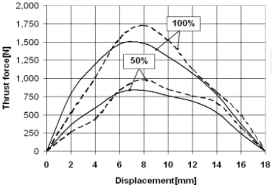
There is a fact that, with the use of EMCN, the objects are modeled as solid state in place of laminated state which they should be in order to save analysis time, so that the flux barrier will be introduced to consider the laminated core characteristics. In term of thrust force, the results for the cases with and without flux barrier will be compared to each other and also compared to the measurement to show the effect of analysis method.
2. ANALYSIS MODEL 2.1 TFLM configuration
Fig 1 (a) shows a 3-dimensional analysis model of a PM excited TFLM with spiral core in a mover. As shown in Fig 1 (b) in detail the mover has a structure in which each of PM is interposed between adjacent two mover cores in order to form a high magnetic flux. This type of TFLM has salient poles on both stator and mover, and the excitation winding is carried by mover. Stator poles are skewed compared to the opposite one. The laminated directions of stator and mover cores are shown in Fig. 2, and the specifications of analysis model are briefly described in table 1. The principle of operation is explained in [4].
2.2 Analysis method.
The magnetic characteristics of the analysis model are calculated by 3-dimensional EMCN. However, one should be noted that in order to save simulation time, either mover or stator are modelled as solid object thus enabling magnetic flux to flow in any direction. This is different from actual state with laminated core.
So that, with the intention of getting high accuracy of analysis in comparison with experimental result, here introduces an imaginary part, 'flux barrier.' Magnetic flux is hard to flow to the lamination direction because of low permeability. In the analysis model, the winding window 'W' as shown in Fig. 2 (a) is the area where flux hardly flow because of both mover and stator core lamination direction.
(a) 3D Full model for one phase (b) 3D insight view Fig. 1 Configuration of a TFLM with spiral core in a mover
(a) Mover core (b) Stator core
Fig. 2 Mover and stator core (arrow is lamination direction)
2009년도 대한전기학회 하계학술대회 논문집 2009. 7. 14 - 17