Online ISSN: 2288-7253 DOI: https://doi.org/10.14579/MEMBRANE_JOURNAL.2018.28.5.297
1. Introduction
1)Hydrogen, the highest energy content per unit of weight, is one of the candidates as an energy source
for next generation. Production, separation and purifi- cation of hydrogen has been continuously kept the sci- entific attention[1-3].
Conventionally, hydrogen is produced by steam re-
†Corresponding author(e-mail: [email protected], http://orcid.org/0000-0002-8003-9698)
막촉매반응기를 이용한 수소생산
도 시 현⋅노 지 수⋅박 호 범†
한양대학교 에너지공학과
(2018년 10월 23일 접수, 2018년 10월 28일 수정, 2018년 10월 28일 채택)
Carbon-free Hydrogen Production Using Membrane Reactors
Si-Hyun Do, Ji Soo Roh, and Ho Bum Park†
Department of Energy Engineering, Hanyang University, Seoul 04763, Korea (Received October 23, 2018, Revised October 28, 2018, Accepted October 28, 2018)
요 약: 본 총설은 분리막기술이 적용된 수소생산에 대한 개론으로, 특히, 암모니아를 수소운반체로 이용하는 수소생산에 대한 연구결과를 중점적으로 서술하였다. 암모니아를 수소운반체로 적용한 수소생산은 추가적인 탄소생성이 없다는 점 외에 여러 측면에 있어 이점이 있다. 많은 연구들이 고순도 수소 분리 및 생산을 위한 분리막 개발을 위해 진행되고 있으며, 이들 중 팔라듐을 기본으로 한 분리막(예를 들어, 다공성 세라믹 또는 다공성 금속 지지체와 팔라듐 합금의 얇은 선택층으로 이루 어진 분리막)에 대한 연구가 활발하다. 반면에, 효율적인 암모니아 분해를 위해서는 주로 루테늄 촉매가 적용되고 있으며, 루 테늄과 지지체 및 촉진제로 이루어진 루테늄에 기반을 둔 촉매에 대한 연구발표가 다수 존재한다. 수소생산을 위한 분리막 반응기 형태로는 충전층, 유동층, 그리고 마이크로반응기 등이 있으며, 이들의 최적화 및 원활한 물질전달 연구는 현재진행형 이다. 또한, 높은 암모니아 분해율, 고순도 수소생산 및 높은 수소생산율을 얻기 위해 분리막과 촉매의 다양한 조합에 대한 연구 및 분리막과 촉매의 역할을 동시에 구현할 수 있는 분리막에 대한 연구가 발표되고 있다.
Abstract: This review focused carbon-free hydrogen productions from ammonia decomposition including inorganic membranes, catalysts and the presently studied reactor configurations. It also contains general information about hydrogen productions from hydrocarbons as hydrogen carriers. A Pd-based membrane (e.g. a porous ceramic or porous metallic support with a thin selective layer of Pd alloy) shows its efficiency to produce the high purity hydrogen. Ru-based catalysts consisted of Ru, support, and promoter are the efficient catalysts for ammonia decomposition. Packed bed membrane reactor (PBMR), Fluidized bed membrane reactor (FBMR), and membrane micro-reactor have been studied mainly for the optimization and the improvement of mass transfer limitation. Various types of reactors, which contain various combinations of hydrogen-selective membranes (i.e. Pd-based membranes) and catalysts (i.e. Ru-based catalysts) including catalytic membrane reactor, have been studied for carbon-free hydrogen production to achieve high ammonia conversion and high hydrogen flux and purity.
Keywords: Pd-based membranes, supported Ru catalysts, catalytic membrane reactor, carbon-free hydrogen production, ammonia decompositions
forming reactions, partial oxidative reactions, and au- to-thermal reforming reactions when various hydro- carbons such as methane, methanol, and ethanol are used as hydrogen carriers[4,5]. The main drawbacks of conventional reactors are equilibrium limited and pro- duce a hydrogen rich gas mixture which is consequently required the hydrogen separation and purification steps[4,5]. The reactors consisted of hydrogen perm-se- lective membranes with catalysts provide a reduction of total reactor volume due to the elimination of the extra hydrogen purification units, a total capital cost reduction due to the milder operation conditions, and a circum- vention of the thermodynamic constraint[4,6,7].
Depending on the types of hydrogen carriers, the rel- evant reactions for methane, methanol, and ethanol to produce hydrogen was shown in Table 1[8]. In con- ventional reactors, methane, methanol, and ethanol re- forming require temperature above 800, 600, and
on the surface of Pd-based membranes[10]. Methanol, which has also been known for a hydrogen storage medium, is successfully performed in membrane re- actors at temperatures below 400°C[11]. Ethanol gen- erally requires higher temperature than methanol, and ethanol reforming at moderate temperature produces the undesirable by-products, formaldehyde, methane, ethylene and carbon[12]. Membrane reactors for the re- forming of hydrocarbons as hydrogen carriers demon- strate the improvement of hydrogen separation and pu- rification, the reduction of by-product, the operation at lower temperatures, and the cost effectiveness.
Ammonia is a promising candidate as hydrogen car- rier due to high energy density (12.8 GJ m
-3), easy of liquefaction at room temperature, and an inexpensive fuel (US$
2012530/ton) that has a well-developed manu- facturing-distribution infrastructure worldwide[13-15].
The use of ammonia as carbon-free hydrogen pro- duction has been repeatedly suggested. Ammonia cata- lytic decomposition (NH
3↔ 1/2 N
2+ 3/2 H
2) is an endothermic process, and it can apply to proton ex- change membrane (PEM) fuel cell. A trace amount of ammonia after hydrogen production sharply degrades the performance of polymer electrolyte fuel cell, but al- kaline fuel cells overcome the negative impact on per- formance until relatively high-volume fractions of am- monia (up to 9%)[16]. The safety of ammonia release at the level of immediately dangerous to life and health (IDLH) limit below 300 ppm should be aware[14].
Obviously, those works imply that the membrane technology is the key to advance the production of high purity hydrogen. This work reviews membrane technologies for hydrogen production. Specifically, it focuses for carbon-free hydrogen productions from am-
CH4 + H2O = CO + 3H2 206.2CH4 + 2H2O = CO2 + 4H2 164.9 CH3OH + H2O = CO2 + 3H2 49 C2H5OH + H2O = 2CO + 4H2 239.5 Partial and full oxidation reactions
CH4 + 2O2 = CO2 + 2H2O -14.4 CH4 + O2 = CO2 + 2H2 -71 CH4 + 1/2O2 = CO2 + 2H2 -35.6 CH3OH + 1/2O2 = CO2 + 2H2 -192.3 C2H5OH + 1/2O2 = 2CO + 3H2 -14.4 Autothermal reforming (ATR) reactions 339
4CH4 + 2H2O + O2 = 10H2 + 4CO 0 4CH3OH + 3H2O + 1/2O2 = 4CO2 + 11H2 -50
C2H5OH + 2H2O + 3/2O2 = 2CO2 + 5H2
monia decomposition, which contains inorganic mem- branes for hydrogen separations, catalysts for ammonia decompositions, and the recent reactor configurations for carbon-free hydrogen productions including general reactor configurations.
2. Membranes for Hydrogen Separation
Membrane materials, specifically inorganics, for hy- drogen separation can be classified as shown in Fig. 1 [4]. Dense metal membranes (mainly palladium-based) and proton conducting membranes show relatively high hydrogen selectivity, while dense metal membranes and microporous ceramic membranes show relatively high hydrogen flux.
Microporous membranes generally have a pore diam- eter smaller than 2 nm, and those are classified into crystalline (e.g. zeolite and metal-organic framework) and amorphous (e.g. silica, carbon, etc.)[4]. To over- come the limitations of microporous ceramic mem- branes (i.e. relatively low hydrogen selectivity by mo- lecular sieving), the thin selective layers (i.e. thickness in the ranges of 1-10 µm) are deposited on porous ce- ramic membranes as supports[4,5].
As proton conducting membrane is concerned, a high purity H
2stream can be recovered by dense ce- ramic membranes at the temperature of 900°C, and a high hydrogen flux can be obtained with high values for protonic and electronic conductivities[4]. Perovskite- type and non-perovskite-type membranes are a sub- category of dense ceramic membranes. Cermet mem-
branes, which are a combination of a ceramic as a pure proton conductor and a metallic as a highly elec- tron conductor, may provide the durability caused by the contact with catalyst particles in the fluidized sus- pension[4,8].
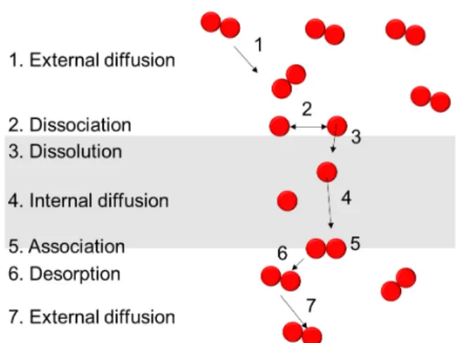
Dense metal membranes are commonly used for high purity hydrogen production, and it follows a sol- ution-diffusion mechanism (Fig. 2)[5]. Palladium (Pd), which is the most well-known material used as dense metal membrane, has excellent permeability, high toler- ance to hydrocarbon flows and self-catalyzing the H
2dissociation reactions[5]. The embrittlement of pure Pd occurs below 298°C and 2 MPa of pressure[17].
Furthermore, the deposition of carbon and the irrever- sible sulfur poisoning occurs when hydrocarbons used as hydrogen carrier[8].
Pd alloy with various metals (i.e. aluminum, copper, indium, molybdenum, nickel, platinum, rhenium, rho- dium, ruthenium, silver, titanium and tungsten) has been tested to overcome embrittlement and poisoning.
Particularly, it is reported that when Pd alloy with sil- ver, it diminishes hydrogen embrittlement[18] while when Pd alloy with copper or gold, it improves resist- ance to H
2S poisoning[19]. Currently, composite Pd-base membranes (i.e. porous ceramic or porous metallic sup- ports with a thin selective layer) are developed for high hydrogen permeability, reasonable thermal stabil- ity, and proper mechanical strength. Performance of the
Fig. 1. Membrane types for hydrogen separation.Fig. 2. Solution-diffusion mechanism for hydrogen separa- tion in metal membrane.
selected membranes for hydrogen separation is shown in Table 2.
A variety of techniques (i.e. electroless plating (ELP), physical vapor deposition (PVD), chemical va- por deposition (CVD), pyrolysis, micro-emulsion tech- nique, electroplating, solvated metal atom deposition and high velocity oxy-fuel spraying (HVOF)) are avail- able for Pd deposition on porous ceramic or porous metallic supports[5]. One of the main methods, ELP, a heterogeneous oxidation-reduction reaction, has advan- tages (i.e. simple equipment, the absence of electrical source, and relatively low temperature) and dis- advantages (i.e. longer preparation time, generation of hazardous liquid wastes). ELP consists of 1) seeding Pd fine particles on the sensitizing and activating sup- port surface and 2) Pd layer plating on top of the acti- vated surface[29]. The deposition of intermediate layers can smooth the initial rough surface of support[29].
Moreover, the pH of solution and temperature are im- portant parameters for deposition[5].
3. Catalysts for Ammonia Decomposition
Catalysts for ammonia decomposition are divided in- to active component, support, and promoter. Various metals (i.e. Fe, Ni, Pt, Ru, Ir, Pd, Rh, etc) have been tested for active component[30]. Of the pure metals, it has been known that ruthenium is the most active
component, even though the precursor of the active component can affect the catalytic performance[13,31].
There can be a maximum Ru loading for ammonia conversion (e.g. a maximum Ru loading of 15 wt% re- ported by Yin et al.)[30]. Moreover, when carbon nanotube (CNT) and SiO
2are used as support, Ru also show the most active for ammonia decomposition [30,32]. With respect to Fe catalysts, it is suggested that the active component is the unstable FeN
x[33]. If the cost is concerned, Ni can be an attractive alter- native[30].
Supports are commonly employed to enhance the dispersion and surface area of the active component.
Unusual but expectedly, the catalytic performance of Ru catalyst is support-dependent[30]. The support for excellent catalytic performance of Ru catalyst should possess basicity, conductivity, the high purity, high thermal stability, and the high dispersion of Ru, and specifically, the higher degree of graphitization as car- bon materials.
Known efficient promoters for supported Ru cata- lysts are alkali, alkaline earth or rare earth metal ions [30]. The promotional effect is dependent on the adopted active component. It is reported that the higher the electronegativity of the promoter, the lower is the ammonia conversion. It has been found that KOH is effective for promoting Ru and Ni/ZrO
2[30].
Ru-based catalysts consisted of Ru, support, and pro-
∞ (H2
Pd-Cu/Al2O3 3.5 623 42,700 7,000 (H2/N2) [26]
Pd/SiO2/PSS 6 773 270 450 (H2/N2) [27]
Pd/NaAZ/PSS 199 723 110,000 608 (H2/N2) [28]
MPSS: macroporous stainless steel, PSS: porous stainless steel.
moter are the efficient catalysts for ammonia decom- position to generate carbon-free hydrogen. However, alternatives including Fe-based and Ni-based catalysts are continuously searched. The activities of Fe-based catalysts are much lower than those of Ru-based cata- lysts and Fe-based catalysts cannot supply the high pu- rity of hydrogen until now[13]. Ni-based catalyst does appear to be a promising catalyst due to its cost ad- vantage over Ru and relatively high activity for ammo- nia decomposition.
4. Reactor Configurations
4.1. Packed bed membrane reactors (PBMR)
PBMR is the simple and well-established configuration. The catalyst in PBMR can be located ei- ther in membrane tube or in the shell side. The gener- alized configuration of PBMR is shown in Fig. 3.
For less membrane surface area required for hydro- gen separation, a sweep gas can be used in the per- meation side of membrane to maintain the permeation hydrogen partial pressure as low as possible[4,5]. The sweep gases can be either reactive (e.g. air or oxygen) or inert (e.g. nitrogen). A sweep gas can be used in ei- ther co-current or counter-current mode (Fig. 4).
Gallucci et al. mathematically simulate ethanol con- version and hydrogen recovery in different sweep gas modes, and they show that high pressure and high temperature lead higher ethanol conversion in the
counter-current mode while the higher ethanol con- version is resulted at low pressure and low temperature in co-current mode[34]. Moreover, the differences in terms of ethanol conversion and hydrogen recovery be- tween co-current and counter-current is negligible at a very large sweep gas flow rate compared to feedstock flow rate[34].
Decreasing the membrane thickness increases mem- brane flux, and the increasing membrane flux reduces membrane area required for separation[4,5]. However, the limitations of hydrogen transport through mem- brane is shifted to the limitation of hydrogen transport between the bulk of catalytic bed and the membrane wall (bed-to-wall mass transfer limitations, which is al- so called concentration polarization) when lower se- lective layer thickness is applied.
The pressure drop and temperature control are other limiting factors in association with PBMR. To decrease the pressure drop, the catalyst particles with large size need to be used, but this reflects in the intra-particle mass transfer, which results in the increasing mem- brane area for certain conversion and recovery[4,5]. A decrease of temperature on the membrane surface de- creases the hydrogen flux through the membrane while an increase of temperature leads to membrane surface cracking, which subsequently decreases the perm-se- lectivity of membrane.
Fig. 3. PBMR with catalysts packed (a) in the tube and (b) in the shell side.
Fig. 4. Catalysts in the tube side PBMR with (a) coun- ter-current mode and (b) co-current mode.
To increase the membrane area per volume of re- actor, multi-tube membrane housing and hollow fiber configuration are investigated[4]. In multi-tube mem- brane housing, the catalyst is loaded in the shell side of reactor while the membrane tubes are connected to a collector for the pure hydrogen[4,35].
4.2. Fluidized bed membrane reactors (FBMR)
FBMR, which is a bundle of hydrogen selective membrane immersed in a catalytic bed operated in the bubbling or turbulent regime, is shown in Fig. 5. The main advantages of using FBMR are 1) the reduction of bed-to-wall mass transfer limitation and 2) the oper- ation at isothermal condition. Negligible pressure drop, flexible arrangement of membrane package, and im- proved fluidization behavior due to compartmentaliza- tion and reducing average bubble size are also benefi- cial[4,5]. On the other hand, the known disadvantages of FBMR are the erosion of inside reactor and catalyst attrition due to vigorous particle motion[5].
Two different membrane reactor configurations, which one is packed bed and the other is fluidized bed operated in the bubbling regime, are theoretically com- pared in case of hydrogen production via methane steam reforming[36]. It reports that both configurations suffer from mass transfer limitations, which FBMR is limited by mass transfer between bubble and emulsion, and PBMR is limited by mass transfer between cata- lytic bed and membrane wall (concentration polar- ization). However, mass transfer limitation for FBMR
can be resolved by breaking up of bubbles while it for PBMR cannot be easily avoided. Moreover, PBMR re- quires more membrane area with respect to FBMR.
4.3. Membrane micro-reactors
Membrane micro-reactor can improve mass and heat transfer using the micro-channels, remove mass transfer limitation (i.e. concentration polarization), and integrate different process steps in a small-scale devise[4].
Microchannel membrane reactor consists of a stain- less-steel feed channel housing with six parallel chan- nels and a ~1.4 µm thick self-supported Pd/Ag mem- brane was reported[37]. It reports that a permeance of hydrogen at 573 K is 1.7 × 10
-2mol m
-2s
-1Pa
-0.5, and the membrane endures differential pressure up to 470 kPa. Even though membrane micro-reactors ignore ex- ternal mass transfer limitations, more research are re- quired to optimization[4].
4.4. Membrane technologies for carbon-free hydrogen production
Interestingly, two systems, which one is membrane
reactor for NH
3decomposition (Fig. 6(a)) and the oth-
er is NH
3cracker integrated with a followed membrane
separator (Fig. 6(b)), are investigated[38]. It is noted
that Fig. 6 is not the exact reactor configuration, but the
conceptual sketches. In both systems, the ultra-thin Pd
membrane, which is supported by porous ceramic tube
modified with aluminum hydroxide gel, is used as the
Fig. 5. Fluidized bed membrane reactor. Fig. 6. The conceptual sketches of (a) membrane reactor for NH3 decomposition and (b) NH3 cracker integrated with a followed membrane separator.hydrogen permeation, and Ni/La-Al
2O
3catalyst is used as ammonia decomposition[38]. Performance of mem- brane reactor for NH
3decomposition shows high NH
3conversion, but an unsatisfactory permeation due to low utilization of Pd membrane[38]. Comparatively, perform- ance of NH
3cracker integrated with a followed mem- brane separator shows high productivity of pure H
2[38].
A multifunctional membrane reactor with Pd mem- brane and Ru-carbon catalyst is evaluated[39]. The po- rous stainless steel is treated to generate a homogeneous oxide layer as an intermediate barrier layer and Pd is de- posited on them[39]. This thin Pd layer on porous stain- less steel is used as hydrogen permeation[39]. A carbon supported Ru is prepared by incipient wetness im- pregnation and NaOH is used as promotor. This Na/Ru-carbon catalyst is used for ammonia decomposition.
The importance of porous stainless steel instead of non-porous stainless steel as support is addressed[39].
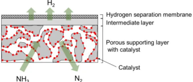
A bimodal catalytic membrane reactor (BCMR) con- sisting of Ru/γ-Al
2O
3/α-Al
2O
3bimodal catalytic sup- port and a hydrogen-selective silica membrane is pro- posed[40]. The conceptual drawing of the reactive membrane is shown in Fig. 7. TEM and SEM images in the study are clearly showed a single unit as a com- bination of catalytic support and a hydrogen-selective membrane[40]. The results show that H
2permeance at 773 K is 6.2 × 10
-7mol m
-2s
-1Pa
-0.5, and ammonia conversion at 723 K after H
2extraction is 95%[40].
Ru catalyst (i.e. the commercial Hypermec 10010 Ru catalyst) with Pd-coated membrane reactor equipped a three-zone heating control without sweep gas is also studied[41]. It performs the higher ammonia conversion (i.e. over 99.5%) and the hydrogen yield (i.e. around
87%) without heating the ammonia tank. Recently, it is reported that the higher ammonia conversion (i.e. 100%) is achieved by multi-stage fixed bed membrane reactors and there is a linear relationship between the number of beds and the feed temperature[42]. Moreover, it also shows that ammonia conversion in a single fixed bed membrane reactor is superior to that in a single fixed bed reactor.
5. Conclusions
Membrane technologies are one of key for hydrogen production. A Pd-based membrane, which is porous ce- ramic or porous metallic support with a thin selective layer of Pd alloy, shows high hydrogen permeability, reasonable thermal stability, and proper mechanical strength. For carbon-free hydrogen production from ammonia decomposition, Ru-based catalysts consisted of Ru, support, and promoter are the efficient catalysts, even though alternatives including Fe-based and Ni-based catalysts are continuously searched. PBMR is commonly operated with a sweep gas. FBMR has the advantages of the reduction of mass transfer limitation and the operation at isothermal condition, but it has the disadvantages of the erosion of inside reactor and the attrition of catalyst. In addition, membrane mi- cro-reactor has been studied to improve mass and heat transfer using the micro-channels for reduction of mass transfer limitation (i.e. concentration polarization).
Various types of reactors and combinations of mem- brane/catalyst (e.g. the ultra-thin Pd membrane sup- ported by porous ceramic tube with Ni/La-Al
2O
3cata- lyst, Pd membrane supported by porous stainless steel with Na/Ru-carbon catalyst, a hydrogen-selective silica membrane on top of Ru/γ-Al
2O
3/α-Al
2O
3bimodal catalytic support, etc.) have been studied to reach high- er ammonia conversion and the higher hydrogen flux and purity.
Fig. 7. The conceptual drawing of the catalytic membrane.