• 검색 결과가 없습니다.

Process Conditions for the Fabrication of Hydrophobic Surfaces with Different Photo-curable Resins

N/A
N/A
Protected

Academic year: 2021

Share "Process Conditions for the Fabrication of Hydrophobic Surfaces with Different Photo-curable Resins"

Copied!
7
0
0

로드 중.... (전체 텍스트 보기)

전체 글

(1)

DOI https://doi.org/10.9725/kts.2020.36.5.267

광경화성 레진의 성분 변화에 대한 소수성 표면 제작을 위한 공정 조건

홍성호1†ㆍ우흥식2

1

동국대학교 창의융합공학부 기계시스템공학전공 조교수

2

동국대학교 창의융합공학부 안전공학전공 교수

Process Conditions for the Fabrication of Hydrophobic Surfaces with Different Photo-curable Resins

Sung-Ho Hong

1†

and Heung-Sik Woo

2

1

Assistant Professor, Dept. of Mechanical System Engineering, Dongguk University-Gyeongju

2

Professor, Dept. of Safety Engineering, Dongguk University-Gyeongju

(Received October 14, 2020 ; Revised October 22, 2020 ; Accepted October 26, 2020)

Abstract − This study experimentally investigates hydrophobic surfaces fabricated via additive manufacturing.

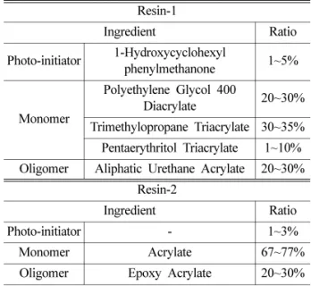
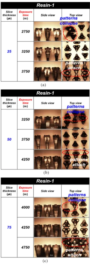
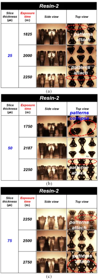
Additive manufacturing, commonly known as 3D printing, is the process of joining materials to fabricate parts from 3D model data, usually in a layer-upon-layer manner. Digital light processing is used to fabricate hydro- phobic surfaces in this study. This method uses photo-curable resins and ultraviolet (UV) sources. Moreover, this technique generally has faster shaping speeds and is advantageous for the fabrication of small components because it enables the fabrication of one layer at a time. Two photo-curable resins with different compositions are used to fabricate micro-patterns of hydrophobic surfaces. The resins are composed of a photo-initiator, mono- mer, and oligomer. Experiments are conducted to determine suitable process conditions for the fabrication of hydrophobic surfaces depending on the type of resin. The most important factors affecting the process conditions are the UV exposure time and slice thickness. The fabrication capability according to the process conditions is evaluated using the side and top views of the micro-patterns observed using a microscope. The micro-patterns are collapsed and intertwined when the exposure time is short because sufficient light (heat) is not applied to cure the photo-curable resin with a given slice thickness. On the other hand, the micro-patterns are attached to each other when the exposure time is prolonged because the over-curing time can cure the periphery of a given shape.

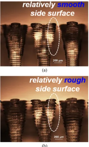
When the slice is thicker, the additional curing area is enlarged in each slice owing to the straightness of UV light, and the slice surface becomes rough.

Keywords − additive manufacturing(적층 제조), contact angle(접촉각), hydrophobic surface(소수성 표면), photo- curable resin( 광경화성 레진)

1. 서 론

최근 고체 표면에 액체의 젖음성(wettability)을 효과적 으로 제어할 수 있는 기술은 과학적, 산업적인 응용 측면

Corresponding author: Sung-Ho Hong Tel: +82-54-770-2211 , Fax: +82-54-770-2870 E-mail: [email protected]

http://orcid.org/0000-0002-3445-0646

ⓒ Korean Tribology Society 2020. This is an open access article distributed under the terms of the Creative Commons Attribution License(CC BY, https://creativecommons.org/

licenses/by/4.0/), which permits unrestricted use, distribution, and reproduction of the work

in any medium, provided the original authors and source are properly cited.

(2)

에서 매우 중요시 되고 있다. 표면의 젖음성은 단순히 기 하학적 형상만의 문제가 아니라 화학적 성분과도 밀접 한 관련이 있다. 젖음성이 낮은 것과 관련된 소수성 (hydrophobicity) 은 주로 연꽃 잎, 나비와 매미의 날개 등 자연모사를 통해 그 해법을 찾으려 하고 있다. 주로 소 수성 표면의 특성은 Fig. 1와 같이 3가지 효과로 설명이 된다. 그 첫번째로 연꽃 잎 효과(lotus effect)로 연꽃 잎 표면은 나노구조 형태로 되어 있으며 표면에 왁스 성분 이 있어 소수성의 특성을 가지게 된다. 두번째는 생이가 래 효과(salvinia effect)로 표면이 수중에서 공기층을 오랫 동안 잡아둘 수 있는 구조로 소수성을 가진다. 마지막으 로 꽃잎 효과(petal effect)는 표면의 거칠기(roughness)으 로 인해 소수성뿐만 아니라 물과의 강한 점착력(adhesion force) 을 나타난다. 꽃잎효과는 큰 접촉각을 유지하면서 도 강한 점착력으로 작은 물방울이 미끄러지지 않게 하 는 특성을 가지고 있다. 그래서 이 꽃잎 효과는 물을 기 름으로부터 용이하게 분리시키는 유수분리기에 많이 활 용된다[1-2].

소수성과 관련된 마이크로 구조물을 제작하기 위해 여 러가지 공정이 연구 중이다. 대표적인 가공 방법으로 기 계 공구를 이용한 가공, photolithograpgy공정, 레이저를 포 함한 에너지 빔을 이용한 공정 등이 있다[3-4]. 그 외에도 적층하여 만드는 적층 제조(AM, additive manufacturing) 기법들을 활용하여 소수성 표면을 제작할 수 있다. 적층 제조 방법을 이용하면 기존의 마이크로 구조물을 제작 하는 방법에서는 구현하기 힘든 곡면과 같은 복잡한 형 상을 가진 구조물을 가공할 수 있다. 적층 제조 방법에 는 Fig. 2와 같이 다양한 방법이 ASTM 53900에 정의 되어 있다. 이 중에서 소수성 표면에 적합한 방법은vat photo-polymerization이다. 이 방법은 광경화성 레진을 이 용하여 UV 같은 광원을 통해 원하는 형상으로 경화시키 는 적층 제조 방법으로 DLP(Digital Light Processing)와 SLA(Stereolithography Apparatus) 가 있다. DLP와 SLA은 Fig. 3, 4 와 같이 경화시키는 방법에서 차이가 있는데 DLP 는 면(area) 단위로 경화를 하는데 SLA는 점(spot) 단위로 경화를 하게 된다. 또한 DLP는 적층방향으로 움

Fig. 1. Lotus, Salvinia and Petal effect.

Fig. 2. Methods of additive manufacturing.

Fig. 3. Process of stereolithography apparatus (SLA) and digital light processing (DLP) [20-21, 23]. (a) SLA process (b) DLP process

Fig. 4. Curing process of SLA and DLP [22-23]. (a)

SLA process (b) DLP process

(3)

직임이 제어되지만 SLA의 경우에는 3축에 대해서 위치 제어가 가능하다. 본 연구에 사용한 DLP는 면 단위로 경 화가 가능하므로 가공 시간이 상대적으로 짧다는 장점 이 있다[5-19].

본 연구에서는 광경화성 레진을 이용하여 적층 구조 물을 만드는 방법 중에 하나인 DLP로 다양한 조건에서 소수성 표면을 제작한 뒤, 광학현미경으로 구조물의 형 상을 살펴 제작물의 완성도를 평가하고 그 공정 조건을 파악하고자 한다.

2. 연구방법 및 내용

2.1. 3D 프린터와 레진

소수성 표면은 광경화성 레진을 이용하여 적층 제조 하며 면 단위의 경화를 하는 DLP 방법을 이용하였다. 이 때 사용된 DLP 장치의 사양은 Table 1와 같다. 사용된 레진들의 성분 및 비율은 Table 2와 같다. 광경화성 레진 은 주로 photo-initiator, monomer, oligomer로 구성되어 있다. Photo-initiator는 레진에 소량으로 첨가하는 성분으 로 UV 램프에서 나오는 빛을 받을 때 중합(polymeri- zation) 을 시작하게 하는 물질이다. 그리고 oligomer는 단 량체로부터 얻어지는 비교적 반복 단위가 작은 저분자 생성물이다. 이때 단량체는 고분자 화합물 또는 회합체 를 구성하는 단위가 되는 분자량이 작은 물질을 의미한

다. Monomer는 같은 화합물의 다른 분자 또는 화합물 과 결합하여 매우 큰 분자나 중합체를 형성하는 화합물 의 한 분자이다. 다작용기성이라 적어도 2개의 서로 다 른 단위체와 화학 결합할 수 있다.

2.2. 마이크로 패턴

제작에 사용된 마이크로 패턴은 Fig. 5와 같다. 마이

Table 1. Specification of DLP

Max. build volume(xyz) Max. resolution 120 mm × 68 × mm × 200 mm 0.047 mm

Table 2. Composition of photo-curable resins.

Resin-1

Ingredient Ratio

Photo-initiator 1-Hydroxycyclohexyl

phenylmethanone 1~5%

Monomer

Polyethylene Glycol 400

Diacrylate 20~30%

Trimethylopropane Triacrylate 30~35%

Pentaerythritol Triacrylate 1~10%

Oligomer Aliphatic Urethane Acrylate 20~30%

Resin-2

Ingredient Ratio

Photo-initiator - 1~3%

Monomer Acrylate 67~77%

Oligomer Epoxy Acrylate 20~30%

Fig. 5. Micro-pattern. (a) salvinia structures (b) shape

of one pattern (c) perspective view of patterns (d) top

view of patterns

(4)

크로 패턴 중 하나의 형상은 Fig. 5(a)와 같이 생이가래 끝단의 형상을 자연 모사한 것으로 Fig. 5(b)와 같이 일 정한 각도를 가지고 세 갈래로 분기되어 있다. 그리고 Fig. 5(c) 와 같이 가로와 세로가 6 mm 크기의 면적에 배 열하였다. 이때 배열은 구조물의 top view를 보여주는 Fig. 5(d) 와 같이 바로 옆의 구조물은 180도 위상이 다른 구조물이 위치하도록 하였다.

3. 결과 및 고찰

3.1. 마이크로 패턴 제작

마이크로 패턴을 제작하는데 중요한 제작 공정인자들 이 있다. 제작하는 한 층(layer)의 두께를 나타내는 slice thickness 와 한 층을 경화하는데 UV를 노출하는 시간인 exposure time 이 구조물을 제작하는데 중요하다. 본 연 구에서는 Table 2에 명시된 2개의 광경화성 레진들을 이 용하여 Table 3와 같은 공정 조건에 대해 제작을 하였다.

Slice thickness 는 25 µm, 50 µm, 75 µm 3가지 경우이고 exposure time 은 레진의 성분에 따라 그 범위를 다르게 설정하였다. Resin-1인 경우가 resin-2인 경우보다 구조 물의 외형을 어느 정도 구현하며 제작하는데 상대적으 로 긴 exposure time이 필요하였다. Fig. 6은 resin-1에 대해서slice thickness에 따라 exposure time을 변화시킬 때 제작된 형상을 옆 면과 위에서 찍은 사진을 보여준 다. 이 그림에서 보면slice thickness가 같은 경우에 exposure time 이 적당한 경우에는 구조물이 뚜렷한 윤곽을 가진 구 조물이 제작된다. 그러나 exposure time이 상대적으로 짧 은 경우에는 구조물이 제대로 형성되지 못하고 형태가 무너지는 현상을 보이고 exposure time이 상대적으로 긴 경우에는 구조물뿐 만 아니라 그 주변의 레진도 경화시 켜 구조물끼리 붙어 있는 현상이 나타난다. 이런 현상들 은 Fig. 7과 같이 resin-2에서도 유사하게 나타난다.

적층 제조 방법을 이용하여 마이크로 패턴을 제작하 는 과정에서 다양한 레진에 대해 slice thickness의 변화 에 의한 적당한 exposure time을 파악하기 위해서는 많 Table 3. Slice thickness and exposure time.

Resin-1 Resin-2

Slice thickness

[µm]

25 50 75 25 50 75

Exposure time [ms]

2750 3250 4000 1825 1750 2250 3250 3750 4250 2000 2180 2500 3750 4250 4750 2250 2250 2750

Fig. 6. Fabrication of micro-pattern with resin-1 with

variation of slice thickness and exposure time. (a) slice

thickness = 25 µm (b) slice thickness = 50 µm (c) slice

thickness = 75 µm

(5)

은 실험이 필요하겠지만, 본 연구에서는 몇가지 경우를 통해 그 경향을 파악하고자 하였다. 따라서 주로 많이 사 용되는 2가지 레진을 이용하여 소수성 표면을 만드는 공 정 조건을 파악하기 위한 실험 만을 수행하였다. 그 결 과 Fig. 8과 같이 레진과 slice thickness의 변화에 대한 적절한 exposure time이 있음을 파악되었다. 마이크로 패 턴을 제작하는 공정에서slice thickness가 증가하면 exposure time 이 길어져야 구조물의 형태가 CAD 모형 과 유사한 모습을 갖는다.

같은 형상에 대해서 slice thickness를 다르게 하면 공 정 시간과 적층된 형태가 다르게 나타난다. 즉 한 층의 두께인 slice thickness가 얇을 경우 같은 크기의 구조물 을 제작하는데 slice thickness가 두꺼운 경우보다 총 공 정 횟수가 늘어남에 따라 공정시간이 길어진다. 또한 slice thickness가 얇으면 경화시키는데 필요한 에너지(열) 이 작기 때문에 적절한 exposure time도 상대적으로 짧 다. 그 반대로 slice thickness를 상대적으로 뚜껍게 하면 공정시간은 짧지만 적절한 exposure time은 길어진다. Fig.

9 는 resin-1에 대해 slice thickness가 50 µm와 75 µm 일 때 적절한 exposure time을 이용하여 제작한 구조물의 옆면 사진이다. 측정된 형태를 살펴보면 slice thickness 가 상대적으로 큰 경우에 옆면의 형상이 거칠게 제작된 다. 그 이유는 Fig. 10에서와 같이 slice thickness가 상대 적으로 크면 구조물의 바깥 경계 부근에서 extra curing area 가 증가하며 적층된 옆면의 형상이 거칠게 나타난다.

Extra curing area 는 UV가 조사되는 방향에 따라 구조물 경계부근에서 추가적으로 레진이 경화되는 면적을 의미 한다. 즉 마이크로 패턴의 구조물을 제작하는데 slice thickness 가 상대적으로 큰 경우에는 공정시간이 짧지만 적층된 옆면의 형상이 CAD의 형상과 많은 차이가 발생

Fig. 7. Fabrication of micro-pattern with resin-2 with variation of slice thickness and exposure time. (a) slice thickness = 25 µm (b) slice thickness = 50 µm (c) slice thickness = 75 µm

Fig. 8. Exposure time condition with variation of resin

and slice thickness.

(6)

할 수 있으므로 구조물의 형상에 따른 적절한 slice thickness 를 결정해야 한다.

4. 결 론

본 연구에서는 광경화성 레진을 이용하여 소수성 표 면을 제작하는 과정에서 레진의 종류에 따라 적절한 공 정 조건을 파악하는 연구를 수행하였다. 공정에서 중요 한 인자는 slice thickness와 UV exposure time 임을 파 악하고 2가지 레진에 대해 그 경향을 파악하였다. Slice

thickness 가 증가하면 적절한 exposure time은 대체적으 로 비례함을 확인하였다. 또한 slice thickness가 큰 경우 에는 적층된 옆면의 형상이 CAD의 형상과 차이가 나는 원인을 파악하였다. 이는 slice thickness가 크면 구조물 주변에 추가적으로 레진이 경화되는 면적이 증가하기 때 문이다.

Acknowledgements

본 연구는 한국연구재단 기초연구사업연구비 (2018 R1C1B 5046698) 지원으로 이루어 졌음.

References

[1] Yang, Y., Li, X., Chen, Z., Zhou, Q., Chen, Y., “3D- printed biomimetic super-hydrophobic structure for microdroplet manipulation and oil/water separa- tion”, Advanced Materials, Vol.30, 1704912, 2018, http://dx.doi.org/10.1002/adma.201704912

[2] Kim, T. W., “A study on the anisotropic flow charac- teristics of droplets on rice leaf surface”, J. Korean Soc. Tribol. Lubr. Eng., Vol.33, No.6, pp.251-255, 2017, https://doi.org/10.9725/kstle.33.6.251

[3] Cho, I. H., Lee, J. H., Noh, J., Lee, S. W., “A study on surface fabrication of super hydrophobic using pico second laser”, Journal of Korean Society for Precision Engineering, Vol.29, No.2, pp.161-169, 2012.

[4] Darband, G. B., Aliofkhazraei, M., Khorsand, S., Sokhanvar, S., Kaboli, A., “Science and engineering of superhydrophobic surfaces: review of corrosion resis- tance, chemical and mechanical stability”, Arabian Journal of Chemistry, Vol.13, No.1, pp.1763-1802, 2020.

[5] Ngo, T. D., Kashani, A., Imbalzano, G., Nguyen, K.

T. Q., Hui, D., “Additive manufacturing (3D printing):

A review of materials, method, applications and chal- lenges”, Composites: Part B, Vol.143, pp.172-196, 2018.

[6] Wang, J., Goyanes, A., Gaisford, S., Basit, A. W.,

“Stereoliyhographic (SLA) 3D printing of oral mod- ified-release dosage forms”, International Journal of Pharmaceutics, Vol.503, pp.207-212, 2016.

[7] Varghese, G., Moral, M., et al., “Fabrication and characterization of ceramics via low-cost DLP 3D printing”, Ceramic y Vidrio, Vol.57, pp.9-18, 2018.

[8] Mu, Q., Wang, L., et al., “Digital light processing 3D Printing of conductive complex structures”, Additive Manufacturing, Vol.18, pp.74-83, 2017.

[9] Bhushan, B., Caspers, M., “An overview of addi- tive manufacturing (3D printing) for microfabrica- tion”, Microsyst. Technol., Vol.23, No.4, pp.1117- Fig. 9. Side view of micro-pattern with resin-1. (a) slice

thickness = 50 µm (b) slice thickness = 75 µm

Fig. 10. Extra curing area with variation of slice

thickness.

(7)

1124, 2017.

[10] Mao, M., He, J., Li, X., Zhang, B., Lei, Q., Liu, Y., Li, D., “The emerging Frontiers and applications of high-resolution 3D printing”, Micromachines, Vol.8, No.4, pp.113, 2017.

[11] Changhai, R., Jun, L., Shaorong, X., Yu, S., “A review of non-contact micro- and nano- printing tech- nologies”, J. Micromech. Microeng., Vol.24, No.5, 053001, 2014.

[12] Wang, X., Jiang, M., Zhou, Z., Gou, J., Hui, D., “3D printing of polymer matrix composites: a review and prospective”, Compos. B Eng., Vol.110, pp.442-458, 2017.

[13] Travitzky, N., Bonet, A., Dermeik, B., Fey, T., Filbert- Demut, I., Schlier, L., Schlordt, T., Greil, P., “Additive manufacturing of ceramic-based materials”, Adv. Eng.

Mater., Vol.16, No.6, pp.729-754, 2014.

[14] Vaezi, M., Seitz, H., Yang, S., “A review on 3D micro-additive manufacturing technologies”, Int. J.

Adv. Manuf. Technol., Vol.67, No.5, pp.1721-1754, 2013.

[15] Eckel, Z. C., Zhou, C., Martin, J. H., Jacobsen, A. J., Carter, W. B., Schaedler, T. A., “Additive manufactur- ing of polymer-derived ceramics”, Science, Vol.351, No.6268, pp. 58-62, 2016.

[16] Manapt, J. Z., Chen, Q., Te, P., Advincula, R. C., “3D printing of polymer nanocomposites via stereolithogra- phy”, Macromol. Mater. Eng., Vol.302, No.9, 1600553,

2017.

[17] Banks, J., “Adding value in additive manufactur- ing: researchers in the United Kingdom and Europe look to 3D printing for customization”, IEEE pulse, Vol.4, No.6, pp.22-26, 2013.

[18] Lee, H., Lim C. H. J., Low, M. J., Tham, N., Muruke- shan, V. M., Kim, Y-J., “Lasers in additive manufactur- ing a review”, Int. J. Precis. Eng. Manuf-Green Technol., Vol.4, No.3, pp.307-322, 2017.

[19] Mohamed, O. A., Masood, S. H., Bhowmik, J. L.,

“Optimization of fused deposition modeling pro- cess parameters: a review of current research and future prospects”, Adv. Manuf., Vol.3, No.1, pp. 42- 53, 2015.

[20] Hong, S. H., “Literature review of fabrication of hydrophobic surfaces with 3D printer”, Proc. Spring Conf. Korean Tribol. Soc., Pusan, Korea, April 2018.

[21] Park, J. H., Park, J. S., Jin, H. J., Hong, S. H., “Fab- rication of hydrophobic surfaces with stereolithogra- phy”, Proc. Spring Conf. Korean Tribol. Soc., Pusan, Korea, April 2018.

[22] Park, J. S., Park, J. H., Jin, H. J., Hong, S. H., “Fab- rication of hydrophobic surfaces with variation of photocurable resins”, Proc. Spring Conf. Korean Tribol. Soc., Pusan, Korea, April 2018.

[23] Hong, S. H., “Fabrication of hydrophobic surfaces

with stereolithography”, Tribol. Lubr., submitted, 2020.

수치

Fig. 1. Lotus, Salvinia and Petal effect.
Fig. 5. Micro-pattern. (a) salvinia structures (b) shape  of one pattern (c) perspective view of patterns (d) top  view of patterns
Fig. 6. Fabrication of micro-pattern with resin-1 with  variation of slice thickness and exposure time
Fig. 7. Fabrication of micro-pattern with resin-2 with  variation of slice thickness and exposure time
+2

참조

관련 문서