Fluid Flow and Heat Transfer in a Super high-Pressure Mercury
Lamp using CFD
Dong Sig Jang, Yeon Won Lee*
1, Kui Ming Li
2, Nanjundan Parthasarathy
2and Yoon Hwan Choi
3RICOH, Tokyo, Japan
1Department of Mechanical & Automotive Engineering, Pukyong National University, Busan 608-739, Korea 2Graduate School of Mechatronics Engineering, Pukyong National University, Busan 608-739, Korea
3BK21, School of Mechanical Engineering, Pukyong National University, Busan 608-739, Korea
(Received June 2, 2012; Accepted November 10, 2012)
Abstract : The discharge properties of super high-pressure mercury lamp are due to resistance heating for energy input, and results in temperature increase. The cooling equilibrium state is reached by the heat conduction, convection and radiation. In order to predict the fluid flow and heat transfer in and around the mercury lamp accurately, its visu-alization is of utmost importance. Such visuvisu-alization is carried out by CFD program in this study. We focus on Anode shape to calculate four cases, namely AA, AB, AC and AD separately, and compare the temperature distribution and velocity vector in each case to predict cooling capacity and fluid flow properties. It can be concluded that the shape of anode plays an important role that affects the fluid flow and heat transfer in a mercury lamp.
Key words : high-pressure mercury lamp, CFD, tungsten electrode
1. Introduction
The mercury vapor lamp is a high intensity discharge lamp. It uses an arc through vaporized mercury in a high pressure tube to create very bright light directly from its own arc [1]. The discharge characteristics of a high-pressure mercury lamp are that, the temperature rises by resistive heating by energy input (electrical energy) and reaches a cooling steady state by conduc-tion, convection and radiation losses of arc. The heat is transferred to the exterior solid glass by means of heat conduction, convection and radiation and the heat that flows away from the exterior solid surface is carried by air, thus cooling the heat using the thermal diffusivity mechanism of discharge characteristics [2-3].
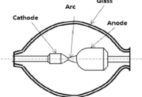
The usage of the parts inside bulb must be of maxi-mum concern such as bright intensity, apt shape, the material type and long life. For such a consideration, the tungsten electrode can meet the above mentioned criteria and can be used in a high-pressure mercury lamp. Fig. 1 shows the structure of the tungsten
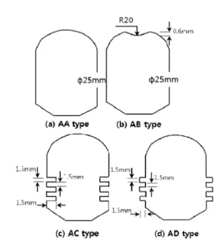
elec-trode of a high-pressure mercury vapor lamp. It consists of an anode, a cathode an arc and a solid glass. The anode is located next to the arc discharge because when at a high temperature, the damage to it will be less and good for excellent cooling capacity. In this study, we focus on anode shapes to study the heat transfer capac-ities. The analysis on fluid flow and heat transfer in the mercury vapor lamp is visualized by CFD simulation. The anode shape is classified into four types as shown in Fig. 2, namely, AA, AB, AC and AD type. AB type
*Corresponding author: ywlee@pknu.ac.kr
is the standard type; others are designed to improve the ability of thermal emission of the lamp shape.
2. Description of the Model
2.1 Basic assumptionsThe calculated model is shown in Fig. 1. We assume an axially symmetric arc in local thermodynamic equi-librium (LTE). We ignore the effects of the magnetic field and sealing material in discharge pipe is assumed as an ideal gas of complete evaporation.
2.2 The governing equations
Under these conditions, the positive column plasma is governed by usual balance equations concerning mass, radial momentum, axial momentum and energy conser-vation. These equations in cylindrical coordinates (r and x) are as follows.
The Continuity Equation
(1) The Axial Momentum Equation
(2)
The Radial Momentum Equation
(3)
The Energy-Balance Equation
(4)
The ideal gas law is given by
(5) The Ohm's law
(6) The basic variables defined by these equations are density ρ, axial velocity vz, radial velocity vr, tempera-ture T and pressure p. The plasma material functions are viscosity η, specific heat Cp, net radioactive emission U, electrical conductivity σ and thermal conductivity k. All these material functions are supposed to be functions of temperature. Other quantities of these equations are elec-tric field E, gravity g, tube radius Rω, electric current I, elementary charge q and the ideal gas constant R. 2.3 Boundary conditions
The boundary conditions shown in Fig. 3 are as fol-lows.
a) Far-field boundary conditions
b) Boundary conditions at the center
∂ρ ∂t --- ∂ ∂x ---(ρvx) 1 r --- ∂ ∂r --- r( ρvr) 0= + + ρ ∂vx ∂t --- vr ∂vx ∂r --- vx ∂vx ∂x ---+ + ⎝ ⎠ ⎛ ⎞ ∂P ∂x ---– = 1 r --- ∂ ∂r --- rη∂vx ∂r ---⎝ ⎠ ⎛ ⎞ ∂ ∂x --- η∂vx ∂x ---⎝ ⎠ ⎛ ⎞ + + ρ ∂vr ∂t --- vr ∂vr ∂r --- vx ∂vr ∂x ---+ + ⎝ ⎠ ⎛ ⎞ ∂P ∂r ---– = 1 r --- ∂ ∂r --- rη∂vr ∂r ---⎝ ⎠ ⎛ ⎞ ∂ ∂x --- η∂vr ∂x ---⎝ ⎠ ⎛ ⎞ η∂vr ∂r2 ---– + + ρCp∂T ∂t --- ρCp vr∂T ∂r --- vx∂T ∂x ---+ ⎝ ⎠ ⎛ ⎞ – + = 1 r --- ∂ ∂r --- rk∂T ∂r ---⎝ ⎠ ⎛ ⎞ ∂ ∂x --- k∂T ∂x ---⎝ ⎠ ⎛ ⎞ + σE2–Urad + + P = RρT E I 2πσr rd 0 R
∫
⎝ ⎠ ⎛ ⎞–1 = ∂vx ∂r --- = 0 T = T0Fig. 2. Anode shape and dimensions.
c) Boundary conditions at both ends of the discharge T = 0, vx= konwn Left side
Right side
d) Solid surface wall flow boundary conditions No- slip
3. Grud Generation and Result Analysis
The numerical model is solved by a SIMPLE algo-rithm of Finite volume method in Fluent. The grid inde-pendence was tested and minimized to a total grid number by 250,000 nodes as shown in Fig. 4.Fig. 5 shows the fluid flow inside the mercury lamp of and around the AA type anode. It can also be seen that the fluid flow inside is convective except for the arc parts, fluid flow is less. But the particles which are melted at the tip from the electrode Tungsten, shown in Fig. 6, is deposited at the rear of low temperature of cathode and anode.
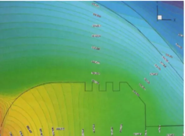
Fig. 7 shows the temperature distribution and stream-line of the outside fluid flow from the left to the right. It can be seen that the temperature is over 6000 K at the center of arc. The temperature is relatively lower near the Cathode parts, which are due to the
phenom-ena of heat conductivity, connectivity and radiation. Vortex is present, though the velocity vector is small near the left and right corner.
Fig. 8 shows the details of temperature distribution. It can be seen that the temperature is over 6000 K, and except at the center, the temperature is almost less than the melting point of the Tungsten.
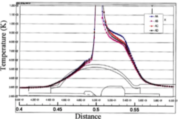
The pattern in the differences can be seen in compar-ison with Fig. 7 and 9. The streamline is closer to the concentric circles for AA type, whereas for the AB type, the flow pattern of the fluid is a distorted gourd-shaped. As a result, the high temperature arc jet fluid flow collides with the center and then moves along the wall to reduce the quantity of heat transfer. This sug-gests that the temperature of the AA type is lower than that of AB, which is well simulated.
∂T ∂r --- = 0 , ∂vx ∂r --- = 0 ∂T ∂x --- 0 ∂vx ∂x --- =0 , =
Fig. 5. Velocity vector Diagram (AA type). Fig. 4. Grid System of the calculated domain.
Fig. 6. Experiment results.
Fig. 7. The fluid flow and temperature distribution of anode of AA shape.
The heat transfer is increased for both AC (Fig. 11, 12) and AD (Fig. 13, 14) types due to creation of strong turbulences. The temperature distribution is lower than AA type. But from the momentum views, due to the loss of energy by rotating fluid flow, results in the fluid flow entrainment to the jet which leads to higher temperature in the front of anode and the cooling capacity of AC type is higher than AD due to the inward fin shape. The results of temperature of the four
types are shown in Fig. 15.
4. Conclusions
A CFD simulation of fluid flow inside a mercury lamp was carried out considering four types of anode shapes of Tungsten electrode. The advantages of this
Fig. 9. The fluid flow and temperature distribution of anode of AB type.
Fig. 10. Details in AB type.
Fig. 11. The fluid flow and temperature distribution of anode of AC type.
Fig. 12. Details in AC type.
Fig. 13. The fluid flow and temperature distribution of anode of AD type.
type of CFD simulations are that it can be clearly sim-ulated and visualized. The fluid flow inside the AB type is convective. Also the flow pattern of the fluid is of a distorted gourd-shaped for this type which results in high temperature and due to this the arc jet fluid flow collides with the center, then moves along the wall
to reduce the quantity of heat transfer. Heat transfer is increased (lower temperature) for both AC and AD types due to occurrences of strong turbulence when compared with the AA type.
References
[1] Tetsu Takemura, Tatsumi Hiramoto, Masaki Yoshioka, and Tatsushi Igarashi, “Three-Dimensional Modeling of a Direct Current Operated Hg-Ar Lamp”, IEEE TRANSACTIONS ON PLASMA SCIENCE., Vol. 34. No. 2, (2006).
[2] Z.Araoud, R.Ben Ahmed, M. Bouaoun, M. Ben EI Hadj Rhouma and K. Charrada, “A dynamic study of the warm-up phase of a high-pressure mercury lamp”, PHYSICS OF PLASMAS 15, (2008).
[3] K. Charrada, G Zissis and M Stambouli, “A study of the convective flow as a function of external parame-ters in high-pressure mercury lamps”, Journal of Phys-ics D: Applied PhhysPhys-ics, Vol. 29, No. 3, pp.753-760, (1996).
Fig. 15. Temperature along the center line for various types of Anode.