P2-113 / J. H. Lim
• IMID 2009 DIGEST
Abstract
Mobile ODF (one drop filling) portable display such as mobile phone and application product is needed high reliability than notebook, monitor and TV. Therefore, material development in order to optimize mobile & application ODF panel is needed. Through considering mobile ODF process and design, we have developed method of material matching test by several tests which is heat stress, UV stress and ODF process condition. So we have developed a material with characteristics of high reliability for mobile ODF panel.
1. Introduction
In LCD business, ODF method is suitable to large size production so this method is applied at almost of new established LCD manufacturing.[1][2] so cell material design and manufacturing process by ODF process has been optimized for large sized TFT-panel.[3] but process control and material development for small sized TFT-panel such as mobile & application was not optimized. The new material design is needed for mobile ODF panel Portable display such as mobile phone and application product is needed high reliability than notebook, monitor and TV. So materials that are applied to the small size of the ODF Products are needed high reliability character at severe environment. In case of small sized panel, after dropping liquid crystal, when TFT-array and color filter assembly, dropped liquid crystal and un-cured sealant is contacted before UV irradiation because small active area. It is induce side Mura caused liquid crystal contamination. In addition, sealant is not 100% harden by shadow area caused by the TFT-array pattern. Part of un-cured sealant makes
more severe side Mura caused by contamination. [4] In the mobile market, small sized ODF panel is required narrow bezel. In order to achieve narrow bezel, liquid crystal, polyimide and sealant will be overlapped structure at a time. It increases the probability of cross-contamination. It is one of the cause about side mura. Therefore, in order to reduce cross-contamination, need to develop high reliability materials that have less cross-contamination.
This paper presents cell material matching test methods for development liquid crystal, polyimide and sealant meet the needs of the market and ODF process.
2. Method of development liquid crystal
Unlike TV and MNT which is used in home or office, portability is the most important factor of mobile display. For satisfy to this character of portability, liquid crystal of mobile should be developed. Especially, mobile display has to be operated long time by low power. And this mobile display needs to be stable operation at low temperature and high temperature environments. So liquid crystal of mobile is essentially needed high dielectric anisotropy, Tni and Tnc for severe environment and portability. But high dielectric anisotropy of liquid crystal is easily occurring image sticking for high polarity which is induced ion absorption in panel. Namely high dielectric anisotropy of liquid crystal is weak that the ion impurities in internal of panel. In case of large sized panel, after dropping liquid crystal, when TFT-array and color filter assembly, dropped liquid crystal and un-curedOptimized Method of Material Matching Test for Mobile
ODF TFT-Panel
Jun Hwan Lim
1, Yun Qiu, Junrui Zhang, Youngyik Ko, Heechul Jung and
Soowoong Hwang
1 R&D center, Chengdu BOE Optoelectronics Technology Co., LTD, No. 1188 Hezuo
Rd, Park West Hi-Tech Zone, Chengdu, Sichuan Province, 611731 China Tel.:86-28-6177-1132, E-mail: limside@boe.com.cn
P2-113 / J. H. Lim
IMID 2009 DIGEST • sealant is not contacted before UV irradiation because
large active area. But small sized panel’s liquid crystal and un-cured sealant is contacted before UV irradiation. It is induce side mura caused liquid crystal contamination by ion impurities. We have developed method of material matching test for improving this defect which is contamination between un-cured sealant and liquid crystal during ODF assembly process. As shown in Ttable.1, we prepared 4 kinds of the high dielectric anisotropy liquid crystal for mobile panel and liquid crystal for MNT.
TABLE 1. Specification of Liquid Crystal
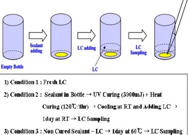
We have made unit cell by several condition. And then we measured VHR and ion density by model 6254 of TOYO at room temperature and 60℃, as shown in Fig. 1.
Fig. 1. Method of LC matching test and condition
Measurement data by various conditions are summarized, as shown Table 2.
TABLE 2. VHR and ion density result of liquid crystal matching test by various conditions
Follow Table 2, unlike fresh liquid crystal of condition#1 and liquid crystal by cured sealant of condition#2, liquid crystal by un-cured sealant of condition#3 is shown high ion density value. In addition, although liquid crystal has similar spec, each liquid crystal has the difference ion result of ion density. This cause is composition of liquid crystal single. Namely, ion absorption value of liquid crystal is changed depending liquid crystal single composition. So we have to do comparative selection about liquid crystal. And because of low polarity of liquid crystal, LC#5 has low ion absorption value.
In ODF process, UV light irradiation is needed for curing sealant. The UV light is unavoidably irradiated to liquid crystal. This situation is induced ion absorption in liquid crystal. So we have made unit cell after 3000mJ, 5000Mj and 7000mJ is irradiated. And then we measured VHR and ion density by model 6254 of TOYO at room temperature and 60℃. The result is as shown Fig. 2.
Fig. 2. Ion density result of LC by UV stress
Follow Fig.2, UV light irradiation is higher ion absorption value of liquid crystal is higher. As a result, Empty Bottle LC adding LC LC Sampling Sealant adding Empty Bottle LC adding LC LC Sampling Sealant adding
P2-113 / J. H. Lim
• IMID 2009 DIGEST
this ion absorption is induced image sticking. In order to reduce UV irradiation to liquid crystal, we have to re-design UV blocking mask or decrease sealing area size. But for narrow bezel which is demand of mobile market, sealing area reducing is impossible.
So we have to develop liquid crystal which is less ion absorption by un-cured sealant and UV irradiation. The above-mentioned, through method of material matching test which is done by ODF process condition and UV stress, we are able to develop high reliability liquid crystal. As a result, we have developed the best LC#2 which is minimized by cross-contamination of between liquid crystal and sealant and UV stress.
3. Method of development Polyimide
Every LCD display which is TV, MNT, NB and Mobile has image sticking. In LCD field, for solving this problem, many LCD researchers had studied various fields which are array design, material design and circuit design. Especially, in cell material design, polyimide is very effective solution on the image sticking. Therefore it is needed new method of material matching test about polyimide for improving this defect. In ODF process, UV light irradiation is needed for curing sealant. The UV light is unavoidably irradiated to polyimide. This situation is induced ion absorption in polyimide. As a result, image sticking become worse than before UV irradiation. In order to check effect by UV irradiates to Polyimide, we have made unit cell after UV 7000mJ is irradiated. And then we measured VHR and ion density by model 6254 of TOYO at 60℃. The result is as shown Table 3.TABLE 3. VHR and Ion density result of Polyimide by UV stress
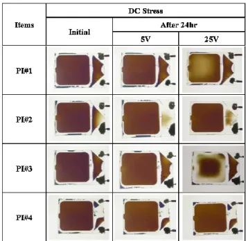
Follow Table 3, VHR and ion density value is higher after UV light irradiation. Especially you can see change of ion density value after UV light irradiation. And as shown Fig.3, we have made unit cell. After we
charge to unit cell at DV 5v and DC 25v during 24hr. we observed disappearance of DC in internal of Panel.
Fig. 3. DC absorption phenomenon by DC stress
As shown Fig.3, after discharging DC 25v, we can know that back to its initial state takes a long time depending on kind of polyimide. This cause is DC absorption of polyimide’s surface. DC absorption of polyimide’s surface interferes with the movement of the liquid crystal molecules. So it is induced image sticking. Therefore, follow those methods of matching test; we need to develop high reliability polyimide which can be strong by UV stress and DC stress.
4. Method of development Sealant
Unlike conventional method using heat type sealant, in ODF method is used hybrid type sealant which is composed optical curing and heat curing. Because this ODF process, liquid crystal have to contact un-cured sealant avoidably during ODF assembly process. It is induced image sticking by contamination of liquid crystal. In addition, in the mobile market, small sized ODF panel is required narrow bezel. In order to achieve narrow bezel, liquid crystal, polyimide and sealant will be overlapped structure at a time. It increases the probability of cross-contamination. It is one of the causes about side Mura. And if side Mura is occurred, image sticking also become worse. So side Mura is the most severe defect by cross-contamination.P2-113 / J. H. Lim
IMID 2009 DIGEST • Generally un-cured sealant is worked with source of
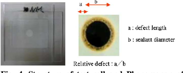
contamination. So we have to develop sealant which is less worked with source of contamination when the sealant is un-cured state. So we made test cell by using 4 kind of the sealant for observation side Mura by contamination. We expressed the side Mura numerically, as shown in Fig. 4. Through various test cells, we measured side Mura for process step by step, as shown in Table 4.
Fig. 4. Structure of test cell and Phenomenon of side Mura by contamination
TABLE 4. Comparison of contaminated side Mura by sealant and process step
ODF sealant is hardened by UV curing, thermal curing in order. According to Table 4, side mura is occurred at thermal curing condition (120℃/45min). It means that if initial curing is insufficient, many areas of sealant are not hardening. It is inducing severe cross-contamination when liquid crystal, polyimide and sealant are overlapped structure. In addition, if high temperature is added in next process step, side Mura will be deepened by high temperature environment. In order words, depending on the type of material, degree of cross-contamination is different. Through material matching test such as test cell is made various sealant combinations, we can develop high reliability sealant for minimize side Mura.
5. Summary
In order to satisfy mobile ODF panel’s spec this is
requireed high reliability characteristics, it is necessary to develop liquid crystal, polyimide and sealant for optimize mobile ODF panel. For satisfy this demand, we have developed method of material matching test that is considered interaction of heat stress, UV stress and ODF process condition for liquid crystal, polyimide and sealant.
According the method of material matching test, we have measured VHR, ion density and side Mura by various test condition. As a result, we are able to develop high reliability for liquid crystal, polyimide and sealant that is less content ion impurities and without side Mura. In addition, the method of material matching test is applied to the mobile ODF panel, as well as the large sized ODF panel.
Acknowledgement
The authors would like to thank contributed engineers in cell part. And we especially thanks to material maker’s engineer who give a lot of advices.
6. References
1. H.Kamiya, Ken Tajima, Kohichi Toriumi, Kazuo Terada, Hiroshi Inoue, Toshinobu Yokoue, Nobuo Shimizu, Takeshi Kobayashi and Shuichi Odahara, SID'01 Digest, pp.1354-1357 (2001)
2. S.Yamada, S. Kimura, N. Sakai, Y. Yamada, H. Matsukawa, S. Hisamitsu, N. Egami, K. Ueno and H. Nagano, SID'01 Digest, pp.1350-1353 (2001) 3. S.H. Chen, H.S. Koo, W.Y. Chen, C.H. Kang and
D.Y. Goang SID’05 Digest, pp.539-541 (2005) 4. J.H Lim, Y.Y Ko, L.Y Hwang, S.Y Park, J.S Park,
H.C Jung and S.W Hwang, SID’09 Digest, pp.1355-1358 (2009)