676 IEEE COMMUNICATIONS LETTERS, VOL. 14, NO. 7, JULY 2010
Multicast Handover Agents for
Fast Handover in Wireless Multicast Networks
Seok Joo Koh and Moneeb Gohar
Abstract—This Letter addresses the fast handover in wireless multicast networks. The existing multicast handover scheme tends to induce unnecessary data transmissions and large han-dover delay during hanhan-dover. We propose a Multicast Hanhan-dover Agent (MHA), which is used to support fast handover and to reduce unnecessary data transmission. In the proposed scheme, each MHA has a cache to maintain a list of active mobile nodes per multicast group, which is used to support the fast leave. The MHA also performs the fast join with its neighboring MHA during handover. By numerical analysis, it is shown that the proposed MHA scheme can give smaller handover delays compared to the existing multicast handover scheme.
Index Terms—Wireless networks, multicast handover agent. I. INTRODUCTION
R
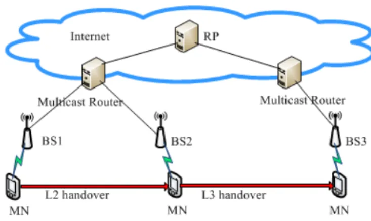
ECENT works on wireless multicasting include the Multimedia Broadcast Multicast Services (MBMS) of 3GPP [1] and the Multicast Broadcast Services (MBS) of IEEE 802.16e [2]. In the MBMS and MBS networks, the wireless link resources are shared for multicast delivery of data packets from a base station (BS) to many mobile nodes (MNs).To support IP multicasting, the Internet Group Management Protocol (IGMP) [3] is used in the wireless access networks. Each BS sends an IGMP query to local MNs, and those local MNs will respond with IGMP reports to BS. Then, this BS will solicit the multicast data packets by forwarding a membership report to its upstream multicast router (MR). In turn, MR requests multicast data packets to the Rendezvous Point (RP) using multicast routing protocols, such as Protocol Independent Multicast (PIM) [4], as shown in Fig. 1.
In the existing multicasting model, when MN moves into a new BS region by handover, it tends to induce unnecessary data transmissions from the old BS during the IGMP leave, since additional query/report messages shall be exchanged between MN and old BS to complete the leave operation. Moreover, the handover delay may get larger, since MN can receive multicast data from the new BS (or MR), only after the IGMP join operations are completed in the new network. To address these problems, we propose to use a Multicast Handover Agent (MHA). In the proposed handover scheme, an MHA is used to reduce unnecessary data transmissions by performing fast leave from the old network, and also to minimize handover delay of MN by performing “fast join” to the new network.
Manuscript received April 6, 2010. The associate editor coordinating the review of this letter and approving it for publication was G. Lazarou.
The authors are with the School of Computer Science and Engineering, Kyungpook National University, Daegu, Korea (e-mail: [email protected], [email protected]).
Digital Object Identifier 10.1109/LCOMM.2010.07.100558
Fig. 1. Existing IP multicasting model in MBMS/MBS.
Fig. 2. Simplified network model for multicast handover.
II. MULTICASTHANDOVEROPERATIONS
A. Network Model
To describe the existing and proposed schemes, we consider a simplified network model, as depicted in Fig. 2. In the figure, MN performs L2 handover by movement from BS1 to BS2, and L3 handover from BS2 to BS3. It is assumed that each BS is equipped with an MHA in the proposed scheme. B. Existing Multicast Handover
We describe the existing multicast handover schemes for L2 and L3 handovers, which are based on the works in [5]. To support handover, we consider the following L2 triggers: Link-Detected (LD) and Link-Up (LU) of the new link, as per the IEEE 802.21 [6].
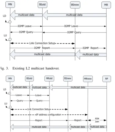
Fig. 3 shows L2 handover operations, in which we assume that MN is the last user to the multicast group in the network. When MN detects a new link, it sends an IGMP leave message to BSold. In turn, the BSold sends a leave message to MR. At this time, BSold will continue to transmit multicast data, until every MN in the access network leaves the group, which will be confirmed by exchanging additional query/leave messages. As MN moves further and gets an LU event of the new link, it establishes a link connection with BSnew and sends an IGMP report to BSnew and further to MR, if necessary. MN can now receive multicast data from BSnew.
Fig. 4 shows L3 handover operations, in which MN moves from MRold to MRnew. When a new link is detected, MN sends a leave message to BSold. Then, BSold will send a leave message to MRold. Similarly to Fig. 3, some query
1089-7798/10$25.00 c⃝ 2010 IEEE
KOH and GOHAR: MULTICAST HANDOVER AGENTS FOR FAST HANDOVER IN WIRELESS MULTICAST NETWORKS 677
Fig. 3. Existing L2 multicast handover.
Fig. 4. Existing L3 multicast handover.
messages are used to confirm the leave event. In L3 handover, MN additionally needs to configure its IP address (e.g., by using DHCP). MN will use this IP address for delivery of IGMP messages in the new network. After that, MN sends an IGMP report to BSnew and toward MRnew. Then, the PIM join process is activated between MRnew and RP.
C. Proposed MHA-based Handover
In the proposed scheme, each MHA maintains a cache that contains the list of active MNs per group. This cache is used to support fast leave and join during handover, in which the list of active MNs may be maintained with a suitable timer.
Fig. 5 shows the proposed L2 handover operations with MHA. When LD trigger is detected, MN sends a leave message to BSold, and then MHA of BSold updates its cache. If MN is the last user to the group (this is confirmed by the cache), MHA shall stop data transmissions and send a leave message to MR. Note that any query message need not be used, since the cache gives enough information on the group leave. At the same time, MHA of BSold initiates the fast join with MHA of BSnew, in which we assume that the LD trigger contains the information of BSnew with the help of IEEE 802.21 [6]. Now, MHA of BSold sends a Handover Request (REQ) message to MHA of BSnew. This HO-REQ message contains information of MN and group address, by which MHA of BSnew sends a report to MR. At this time, the multicast data will be buffered at BSnew. With LU event, a new link connection is established, and MN can receive multicast data from BSnew.
Fig. 6 shows L3 handover operations with MHA. Similarly to Fig. 5, MHA of BSold will update its cache and stop data
Fig. 5. Proposed L2 multicast handover with MHA.
Fig. 6. Proposed L3 multicast handover with MHA.
transmissions with an IGMP leave. For fast join, HO-REQ is transferred from MHA of BSold to MHA of BSnew, and MHA of BSnew will send an IGMP report to MRnew. Then, PIM join is performed between MRnew and RP. At this time, the multicast data will be buffered at BSnew. With the connection setup of a new link, MN can receive multicast data from BSnew, without IP address configuration, since the join has already been completed when MN is in the old network.
III. ANALYSIS OFHANDOVERDELAY
For performance analysis, we compare handover delays for the existing and proposed schemes. For analysis, we consider a network model of Fig. 2, and define𝑇𝐴−𝐵 as the transmission
delay between two nodes𝐴 and 𝐵.
From Fig. 3, we see that the handover delay (HOD) for the existing L2 handover includes the following components:
1) Transmission of IGMP leave from MN to MR via BSold, which is𝑇𝑀𝑁−𝐵𝑆+ 𝑇𝐵𝑆−𝑀𝑅;
2) Transmission of IGMP query from MR to MN via BSold, which is𝑇𝐵𝑆−𝑀𝑅+ 𝑇𝑀𝑁−𝐵𝑆;
3) Link connection setup time is ignored;
4) Transmission of IGMP report from MN to MR via BSnew, which is𝑇𝑀𝑁−𝐵𝑆+ 𝑇𝐵𝑆−𝑀𝑅.
Thus, the existing𝐻𝑂𝐷𝐿2𝐻𝑂 is represented as
3𝑇𝑀𝑁−𝐵𝑆+ 3𝑇𝐵𝑆−𝑀𝑅 (1)
Similarly, in Fig. 4, the HOD for existing L3 multicast handover can be calculated with the following delays:
1) IGMP leave/query between MN and BSold, and between BSold and MRold, which is2𝑇𝑀𝑁−𝐵𝑆+ 2𝑇𝐵𝑆−𝑀𝑅;
2) Address configuration to MRnew, which is𝑇𝐴𝐶;
678 IEEE COMMUNICATIONS LETTERS, VOL. 14, NO. 7, JULY 2010
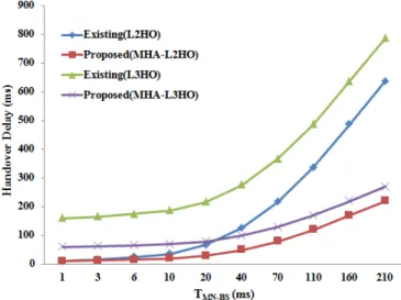
Fig. 7. Impact of transmission delay between MN and BS.
Fig. 8. Impact of transmission delay between BS and MR.
3) Transmission of IGMP report from MN to BSnew and further to MRnew, which is𝑇𝑀𝑁−𝐵𝑆+ 𝑇𝐵𝑆−𝑀𝑅;
4) PIM join between MRnew and RP, which is2𝑇𝑀𝑅−𝑅𝑃.
Thus, the existing𝐻𝑂𝐷𝐿3𝐻𝑂 is represented as
3𝑇𝑀𝑁−𝐵𝑆+ 3𝑇𝐵𝑆−𝑀𝑅+ 2𝑇𝑀𝑅−𝑅𝑃 + 𝑇𝐴𝐶 (2)
On the other hand, in Fig. 5, HOD for L2 handover with the proposed MHA is obtained with the following components:
1) IGMP leave message from MN to BSold, and from BSold to MR, which is 𝑇𝑀𝑁−𝐵𝑆+ 𝑇𝐵𝑆−𝑀𝑅;
2) HO-REQ message from BSold to BSnew, 𝑇𝐵𝑆−𝐵𝑆;
3) IGMP report from BSnew to MR, which is 𝑇𝐵𝑆−𝑀𝑅.
Thus, the proposed𝐻𝑂𝐷𝑀𝐻𝐴−𝐿2𝐻𝑂 can be
𝑇𝑀𝑁−𝐵𝑆+ 2𝑇𝐵𝑆−𝑀𝑅+ 𝑇𝐵𝑆−𝐵𝑆 (3)
Finally, in Fig. 6, HOD of the proposed L3 handover with MHA can be calculated as follows:
1) IGMP leave message from MN to BSold, and from BSold to MRold, which is 𝑇𝑀𝑁−𝐵𝑆+ 𝑇𝐵𝑆−𝑀𝑅;
2) HO-REQ message from BSold to BSnew, 𝑇𝐵𝑆−𝐵𝑆;
3) IGMP report from BSnew to MRnew,𝑇𝐵𝑆−𝑀𝑅.
4) PIM join between MRnew and RP, which is2𝑇𝑀𝑅−𝑅𝑃.
Thus, the proposed𝐻𝑂𝐷𝑀𝐻𝐴−𝐿3𝐻𝑂 can be
𝑇𝑀𝑁−𝐵𝑆+ 2𝑇𝐵𝑆−𝑀𝑅+ 𝑇𝐵𝑆−𝐵𝑆+ 2𝑇𝑀𝑅−𝑅𝑃 (4)
Now, we compare the handover delays of candidate schemes by numerical analysis. Based on the parameter values of the 3G cellular systems that were suggested in [7], we employ the parameter values as follows:𝑇𝑀𝑁−𝐵𝑆 is set to 10ms by
default and varies from 1ms to 210ms;𝑇𝐵𝑆−𝐵𝑆is set to 5ms;
𝑇𝐵𝑆−𝑀𝑅 is set to 2ms by default and varies from 1ms to
56ms; and𝑇𝑀𝑅−𝑅𝑃 is set to 25ms. In addition,we set𝑇𝐴𝐶to
100ms. Note that𝑇𝑀𝑁−𝐵𝑆 and𝑇𝐵𝑆−𝑀𝑅vary because these
values tend to depend on the dynamic network conditions. In Fig. 7, we can see that the handover delays get larger for all the schemes, as𝑇𝑀𝑁−𝐵𝑆increases. However, the proposed
MHA schemes provide much smaller handover delays than the existing schemes for both L2 and L3 handovers. Moreover, it is noted that the gap of performances between the existing and proposed schemes gets larger, as𝑇𝑀𝑁−𝐵𝑆 increases.
Fig. 8 shows that the proposed MHA schemes provide better performances than the existing ones, as 𝑇𝐵𝑆−𝑀𝑅 increases.
For a large value of 𝑇𝐵𝑆−𝑀𝑅, the L3 handover delay of the
proposed scheme is smaller than the L2 handover delay of the existing scheme. It is noted that this handover performance benefit comes from the use of MHA, which is a special agent used for fast handover that shall be additionally deployed over BS in the network.
IV. CONCLUSION
This Letter proposes a multicast handover agent (MHA) for support of fast handover in wireless multicast networks. From numerical analysis, we can see that the proposed schemes give much smaller handover delays than the existing ones.
ACKNOWLEDGMENT
This research was supported by the IT Research and De-velopment program of MKE/KEIT(10035245) and the ITRC program of MKE/NIPA(NIPA-2010-C1090-1021-0002).
REFERENCES
[1] 3GPP TS 22.246, Multimedia Broadcast Multicast Service (MBMS) User Services,V7.0.0, Sep. 1999.
[2] T. jiang, et al., “Multicast broadcast services support in OFDMA-based WiMAX systems,” IEEE Commun. Mag., pp. 78-86, May 2008. [3] IETF RFC 5186, IGMPv3/MLDv2 and Multicast Routing Protocol
Inter-action, Aug. 2007.
[4] IETF RFC 4601, Protocol Independent Multicast - Sparse Mode (PIM-SM): Protocol Specification (Revised), Aug. 2007.
[5] I. Romdhani, et al., “IP mobile multicast: challenges and solutions,” IEEE
Commun. Surveys and Tutorials, vol. 6, no. 1, pp. 18-41, Mar. 2004.
[6] IEEE 802.21, Local and Metropolitan Area Networks: Media Independent Handover (MIH) Services, 2006.
[7] H. Faithi and R. Prasad, “Mobility management for VoIP in 3G systems: evaluation of low-latency handoff schemes,” IEEE Wireless Commun., vol. 12, no. 2, pp. 96-104, Apr. 2005.