Vol.14, No.6, pp.26-35 (2020)
Designing Flexible Packets for Multi-Satellite Data Transmission in a Physical Network Separation Environment
Hyun Chul Baek1,†, Sang Jeong Lee2
1Korea Aerospace Research Institute
2Chungnam National University
Abstract
The national satellite operation network, which supports multiple satellites, was designated as a Critical Information Infrastructure (CII) in 2017. The network was designed independently from the control network and the information network to enhance physical security. Planning is underway to establish a bidirectional data interface between networks. The data transmission system allows data flow only to the physical layer and the data link layer; hence, only one file can be transferred at any one time. This means that when large amounts of data are being transmitted, no other data can be sent simultaneously in urgent situations. Thus, this paper discusses the design of flexible packets for the transmission of data between networks in an environment where physical security has been enhanced through network separation and based on this, presents a method for transmitting data effectively.
Key Words: Multi-Satellite Operation, Security Network, Critical Information Infrastructure, One-way System
1. Introduction
Current cybersecurity primarily deals with advanced persistent threats (APT). APTs persistently attack specific targets to achieve various objectives. These objectives relate to military, diplomatic, cultural, and monetary profits, unlike past threats that attempted to achieve political and social goals.
Phishing, pharming, and smishing attacks against infrastructure facilities also occur frequently, and they aim to steal information and money, threatening people’s lives and property. Moreover, ransomware targeting personal property and large-scale cyber-attacks that manipulate the internet of things devices are also sweeping the world. Cybersecurity threats mostly bypass existing security systems, taking advantage of software vulnerabilities or malware that can access specific systems. Malware infiltrates or infects systems when recipients of emails or messenger messages open an attached file or when users access external storage media or untrusted websites on the internet. To respond to cyber-attacks, corporations and institutions reinforce security policies by installing information protection systems such as firewalls, intrusion detection and protection systems, and other security solutions such as event management. In addition, they protect their assets by separating the network. In particular, network
separation to block the external internet has been legalized as an obligation under Article 15 (2)-3 of the Enforcement Decree of the Act on Promotion of Information and Communications Network Utilization and Information Protection, Etc., and Article 30 (1)-2 of the Enforcement Decree of the Personal Information Protection Act. Guidelines for strengthening security are being formulated. Network separation can minimize damages by limiting the operating range of malware. This enhances security by protecting intranet data [1]. However, although the inflow of malware can be blocked by physical network separation, convenience and efficiency of work can deteriorate due to the lack of connection to external networks. To solve this problem, an inter-network data transfer system can be constructed using a secure USB, a one-way transmission system, and other tools.
According to the Act on the Protection of Information and Communications Infrastructure, which has been in force since 2001, critical information and communication infrastructure facilities have been designated. These designated facilities are analyzed and assessed for vulnerabilities, and protective measures are established. These measures are monitored periodically to protect nationally and socially important facilities from external threats such as viruses, hacking, and denial of service. The National Satellite Operation Network, which operates multiple satellites, was designated as a major information and communication infrastructure facility in 2017.
To strengthen the physical security of this facility, the control Received: Jul. 27, 2020 Revised: Oct. 04, 2020 Accepted: Oct. 05, 2020
† Corresponding Author
Tel: +82-42-821-6582, E-mail: [email protected]
Ⓒ The Society for Aerospace System Engineering
network (major information and communication infrastructure facility) was designated separately from the information network. Planning is underway for the construction of a bidirectional inter-network data transfer system to develop an efficient data transfer interface between the two networks. To improve the security environment, the inter-network data transfer system will be designed to allow data transmission only to the physical layer and data link layer. However, this has a disadvantage in that only one file can be transferred at any one time through the transmission line. This means that it is impossible to send different data simultaneously, even in urgent situations. To address such a problem, this study designed packets to enable efficient data transfer between networks in an environment with enhanced physical security achieved through network separation. This paper proposes an optimized data transfer method including data analysis and time shortening based on flexible packets.
2. Security Threat
2.1 Inflow of malware
Network separation can minimize damage even when a problem occurs by limiting the operating range of the malware.
However, besides executable files, organizations must be prepared for attacks on various file types. They must be able to cope with new and variant malware that can bypass the conventional security environment. The sandbox bypass technique aims at providing a secure environment where untrusted programs are confined to operating within a limited area without affecting other parts of the system. To that end, the content disarm and reconstruction (CDR) technology removes unnecessary data, such as malware or hidden data while adding or reading files. The CDR performs this operation by analyzing file structure. In the past, attacks were carried out primarily using executable files; however, because of the improved performance of anti-virus programs and strengthened security policies of companies, attack patterns are changing—malware are being attached to documents in the e-mails or shared folders [1].
2.2 Analysis of vulnerabilities
There are various methods of malware attack using document files such as vulnerabilities, scripts, and encapsulated postscripts (EPS). The malware insertion method uses structurally unused areas inside document files. For the widely used Portable Document Format (PDF), 849 common vulnerabilities and exposures (CVEs) have been found. For the Compound File Binary Format (CFBF), used by Hangul and Microsoft Office documents (version 2003 or lower), unused space, slack space area, and reserved spaces are used as data hiding areas.
As with CFBF, malware using macros or VB scripts can be inserted in Open Document Format (ODF) and Open Office
XML (OOXML) used in Microsoft Office documents (version 2007 or higher), and data can be secretly inserted in XML files inside documents. The malignancy of these files can be determined using a method that can analyze and detect them in a virtual environment, but it may be difficult to detect them by the application of a sandbox bypass technique as shown in Fig.
1 [1].
Fig. 1 Cybersecurity incidents [2]
3. Network Separation and Inter-Network Data Transfer System
3.1 Network separation technique
Security incidents such as paralysis of the internal network due to malware infection, destruction of internal systems, and leakage of internal information by insiders are caused because internal user PCs are connected to the external networks such as the internet. Network separation means creating a separation in the internal PC environment between the internet and the intranet. This prevents the inflow of malware into the internal intranet and the leakage of important information from the internal systems to the external internet. In other words, it refers to a structure in which the network environment for internal work is blocked from the external Internet, and the access to the internal intranet is blocked when the external internet is being accessed. Network separation began to be applied to national and public organizations in 2008, and companies are also required by the information and communications laws to apply network separation to PCs accessing personal information processing systems. Network separation techniques can be largely divided into physical and logical methods depending on the implementation method [3].
3.2 Considerations when introducing network separation
Network separation techniques have both advantages and disadvantages depending on the implementation method.
These are shown in Table 1. Physical network separation has
limitations in mobility such as accessing wireless LAN.
Logical network separation is convenient for users as it allows them to use server-based computing (SBC) or client-based computing (CBC) from one PC. However, logical network separation requires a separate network configuration for the SBC or CBC environment. Furthermore, when it is necessary to transfer data between the intranet and the external internet, both physical and logical network separations require separate environment configurations for file transfer.
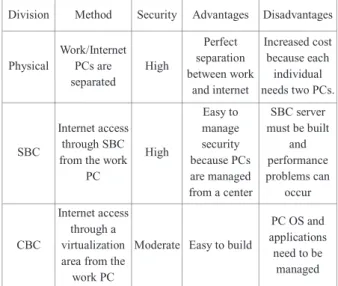
Table 1 Comparison of network separation technique Division Method Security Advantages Disadvantages
Physical
Work/Internet PCs are separated
High
Perfect separation between work
and internet
Increased cost because each individual needs two PCs.
SBC
Internet access through SBC from the work
PC
High
Easy to manage security because PCs are managed from a center
SBC server must be built
and performance problems can
occur
CBC
Internet access through a virtualization area from the work PC
Moderate Easy to build
PC OS and applications need to be
managed
Major vulnerabilities include virus infection due to the exchange of data infected by malware via USB memory sticks (even if USBs are permitted), virus infection of the work PCs due to infected files downloaded from the internet being sent to the intranet, and intentional data leakage by insiders [3].
3.3 Inter-network data transfer technology
Network separation can prevent the leakage of important internal information and block external hacking threats by separating the intranet from the internet. However, this type of network separation decreases the work efficiency of users because of the complexity of procedures. Many studies have been conducted on the efficient performance of inter-network data transfer in a network separation environment. Security management methods include storage method, socket method, automatic switch using a serial interface, relay system, shared storage, dedicated cable, secure USB, and one-way systems.
These methods allow data transfer while maintaining internal security. Secure USB, the most widely used method, is useful because it is cheap and can store a large amount of data;
however, it has a serious limitation regarding security. Many recent information leakage incidents have occurred through USB. Secure USBs are used to overcome this shortcoming;
however, they also present the possibility of information leakage. Consequently, there is a trend of switching to
bidirectional inter-network data transfer systems.
3.4 Considerations when introducing inter-network data transfer system
Network separation still has vulnerabilities; therefore, continued management and process maintenance are critical even after network separation. To that end, it is necessary to develop an approval system for inter-network data transfer and build a log management system or abnormal sign detection/processing system to collect and analyze data transferred between networks. Another method is to have an integrated management system that can check virus/malware infection during inter-network data transfer. This management system consists of an interface between the inter-network data transfer and malware analysis systems [3].
4. Data Packet Design for Inter-network Data Transfer
4.1 Building an inter-network data transfer system The Act on the Protection of Information and Communications Infrastructure was enacted in 2001. It aims to ensure national safety and the stability of people’s lives through the stable operations of critical information infrastructures (CII). This is ensured by establishing and implementing measures to protect CII against electronic infringements. The CII consist of nationally and socially important information and communication facilities that need to be protected from different modes of infiltration such as electronic virus, hacking, and denial of service attacks. When the government and public organizations are subject to external attacks, social confusion can result. Facilities designated as CII must establish and carry out measures to periodically analyze, evaluate, and protect vulnerabilities.
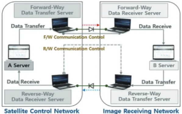
Fig. 2 Transmitting data between networks Currently, Korea Aerospace Research Institute is operating four Arirang satellites, each of which passes above the Korean Peninsula three to four times a day, providing various earth
observation data. To stably operate the multiple satellites, the multiple satellite network of the Korea Aerospace Research Institute’s National Satellite Utilization Support Center has been designated as a major information and communication infrastructure facility since 2017. To prevent external hacking and virus inflow, the network for multiple satellite operation was physically separated into a control network (designated as a major information and communication infrastructure facility) and an information network. This separation caused inconvenience to users and concerns about how inter-network data transfer could be performed efficiently. The use of secure USB, which is the most widely used method, was considered;
however, considering that a recent information leakage incident mostly occurred through secure USB, a different method had to be developed. The most reasonable solution for the inter-network data transfer was to build a bidirectional data transfer system using two sets of one-way systems. The bidirectional data transfer method that only supports the physical layer and the data link layer (Fig. 2 B) was selected instead of the product that supports all the seven layers of the OSI as shown in Fig. 2 A.
Fig. 3 Configuration of data interface
Since a one-way system cannot receive a response (ACK) after sending data, it cannot respond to a transfer data error or loss/error of the receiver. However, as shown in Fig. 3, the bidirectional filter transfer system can support the error correcting code (ECC) for file transfers.
Fig. 4 Sequential data transfer method
It uses a physical line and detects any troubles of the
receiver through the line monitoring function, resending data after buffering. The inter-network data transfer system has advantages in security and integrated management aspects because it sets and manages security policies for the forward (control network → information network) and backward (information network → control network) directions through the physical line in the control area. Furthermore, it can block harmful external traffic because it is designed in such a way that it can send all data in the forward direction, but can only send text files in the backward direction.
4.2 Inter-network data transfer using physical port The data transfer method is limited to the physical layer and the data link layer has a disadvantage—only one data unit can be sent at any one time, as shown in Fig. 4. Since the amount of data to be transferred is likely to increase, considering the operation of multiple satellites and the fact that more satellites will be launched in the future, the occupation of the transmission lines by a large quantity of data will affect data transmission in the event of an emergency such as national disasters. For example, when large data such as satellite images are being transmitted, if there is other data that needs to be sent urgently, the process must be put on hold until the current data is fully transmitted. Satellite image data sent by one Arirang satellite in one pass is 12 Gbytes. Thus, assuming that the transmission bandwidth of the inter-network data transfer system is 40 Mbytes, the inter-network data transfer takes approximately 309 s; even if an emergency occurs during this time, its transmission must be put on hold until the previous data transfer is complete.
Fig. 5 Physical separation based on bandwidth
To solve the problem of the transmission line being occupied by large data, a method of separating the bandwidth using a port based on the physical layer was considered. As shown in Fig 5, it is designed to have sub-channels of 20 Mbytes by dividing the total transmission bandwidth of 40 Mbytes into two ports. It uses the inter-network data transfer system that sends data to the directory after the virus and any possible hacking are checked. Using the two ports, 20 Mbytes each of large data, such as satellite images, is allocated to one sub-channel and the remaining data is allocated to the other sub-channel. This is an effective method when transmitting
urgent data; however, it has a limitation of reduced data transfer rate—it takes approximately 600 s to send 12 Gbytes satellite images. A reasonable solution to this problem is to set the transmission bandwidth in the physical layer differently to 1/10/20 Mbytes. However, although the bandwidth can be divided, the system did not support setting the bandwidth differently due to the nature of the hardware equipment.
4.3 Fixed packet design for inter-network data transfer
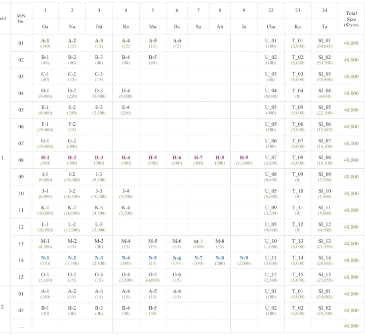
The System that need inter-network data transfer between the control network and information network, as well as the interface items, are outlined in Table 2. Columns signify the minor frame and rows signify the data that must be transferred.
The packets for minor frames were designed to be expandable using frame No. 16 and 17, and the data interface items corresponding to the rows were designed to be fit for each data size. Every data format includes a 10% margin based on the data analysis results. The packet size was determined by adding header and tailor information to the data to be transmitted.
Furthermore, although it was not defined in the current packet in each system, an undefined packet corresponding to 25% of the total size was defined for each minor frame considering the future expandability. In addition, the telemetry and satellite images, which are relatively large, were allocated to fixed packets. The image data packets were designed to be expandable when the transmission bandwidth increases.
Table 2 Fixed packet design for data interface (Kbytes)
M/J M/N No.
1 2 3 4 5 6 7 8 9 22 23 24 Total Size (Kbytes)
Ga Na Da Ra Ma Ba Sa Ah Ja Cha Ka Ta
1
01 A-1
(140) A-2
(15) A-3
(15) A-4
(15) A-5
(15) A-6
(15) U_01
(100) T_01
(5,000) SI_01
(34,685) 40,000 02 B-1
(40) B-2
(40) B-3
(40) B-4
(40) B-5
(40) U_02
(100) T_02
(5,000) SI_02
(34,700) 40,000 03 C-1
(40) C-2
(15) C-3
(15) U_03
(40) T_03
(5,000) SI_03
(34,890) 40,000 04 D-1
(9,000) D-2
(250) D-3
(9,000) D-4
(9,000) U_04
(8,000) T_04
(0) SI_04
(4,650) 40,000 05 E-1
(9,000) E-2
(250) E-3
(2,500) E-4
(250) U_05
(900) T_05
(5,000) SI_05
(22,100) 40,000 06 F-1
(19,000) F-2
(15) U_05
(500) T_06
(5,000) SI_06
(15,485) 40,000 07 G-1
(19,000) G-2
(300) U_06
(500) T_07
(5,000) SI_07
(18,100) 40,000
08 H-1
(300) H-2
(300) H-3
(300) H-4
(300) H-5
(300) H-6
(300) H-7
(300) H-8
(300) H-9
(11,000) U_07
(3,500) T_08
(5,000) SI_08
(18,100) 40,000 09 I-1
(9,000) I-2
(10,000) I-3
(9,500) U_08
(8,000) T_09
(0) SI_09
(3,500) 40,000 10 J-1
(6,000) J-2
(10,500) J-3
(10,200) J-4
(3,500) U_05
(8,000) T_10
(0) SI_10
(1,800) 40,000 11 K-1
(10,000) K-2
(10,000) K-3
(4,500) K-4
(3,500) U_09
(3,200) T_11
(0) SI_11
(8,800) 40,000 12 L-1
(10,500) L-2
(11,000) L-3
(5,000) U_05
(9,000) T_12
(0) SI_12
(4,500) 40,000 13 M-1
(8,500) M-2
(15) M-3
(30) M-4
(15) M-5
(15) M-6
(15) M-7
(4,000)
M-8
(15) U_10
(1,000) T_13
(5,000) SI_13
(21,395) 40,000 14 N-1
(170) N-2
(1,700) N-3
(2,800) N-4
(300) N-5
(15) N-6
(3,500)
N-7
(350) N-8
(200) N-9
(2,000) U_11
(3,000) T_14
(5,000) SI_14
(20,965) 40,000 15 O-1
(1,100) O-2
(15) O-3
(15) O-4
(3,500) O-5
(4,000) O-6
(15) U_12
(2,500) T_15
(5,000) SI_15
(23,855) 40,000
2
01 A-1
(140) A-2
(15) A-3
(15) A-4
(15) A-5
(15) A-6
(15) U_01
(100) T_01
(5,000) SI_01
(34,685) 40,000 02 B-1
(40) B-2
(40) B-3
(40) B-4
(40) B-5
(40) U_02
(100) T_02
(5,000) SI_02
(34,700) 40,000 ... 40,000
※ U: Undefined Packet ※ T: Telemetry ※ SI: Satellite Image
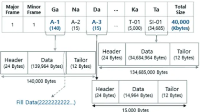
Fig. 6 Data transfer method with fixed packets
The telemetry data were fixed to 5 Mbytes. For the image data, the data to be transmitted from each frame, based on the total data transfer bandwidth of 40 Mbytes and the remainder excluding the undefined and telemetry, were allocated. Each packet includes Header (24 Bytes) + Data + Tailor (12 Bytes) as shown in Fig. 6. If the data length is smaller than the fixed format, the empty packet is filled using Fill Data.
Table 3 shows the header and tailor information required for data transfer. These are generated based on the input system and file names. For example, the data of the content ‘Ga’ of Minor Frame 1 are IP file sent from the Image Collection Planning System (ICPS) to the Mission Planning System (MPS) and means “A-1”. “A-1” contains all ICP files required to operate multiple satellites such as Arirang 3 (K3) and Arirang 5 (K5). Since they are generated at separate times, only one file is sent for one satellite. For example, when the file “K3_yyyymmddhhmmss_01.osl” is transmitted, it can be expressed as “010102 xxxxxxxxxxxxxx 01000001020000 ~ 0000FFFF555555555555XX”. This can be interpreted as
follows: Minor Frame ’01,’ K3 satellite of Content ‘Ga,’ year, month, day, hour, minute and second, the station and antenna undefined yet (‘00’), the data is first sent from the ICPS to the MPS (for variable, Fill Data ‘222222~’), and the file is composed of one file without continued files.
Furthermore, data can be sent to a minor frame by determining at which minor frame the data is located using the file name of the data and adding the destination information.
When one major frame is composed of minor frames based on the fixed packet, telemetry is composed of 50 Mbytes and satellite image data is composed of 251,610 Kbytes. Thus, one minor frame can be defined as 16,774 Kbytes. To transmit satellite image data of 12 Gbytes, approximately 680 s is required, and all the data can be sent in 48 major frames.
If data are input from a specific system during the transfer of satellite images, the data are transmitted using the fixed packets of the corresponding minor frame. In the case of Image Collection Plan (ICP), 10 files/day are generated for each satellite, and in the case of GPF Generation Software (GGS), 20 files/day are generated. Since the same fixed packets are used, the system must wait 15 s to transmit the next file after sending one file. As a result, it takes 150 s in total to send 10 ICP files and 300 s in total to send 20 GGS files.
4.4 Design of flexible packets for inter-network data transfer
Using fixed packets to transmit data has an advantage—all data, including large data, can be transmitted within a fixed time.
Table 3 Packet header & tailor design
M/F Content SAT Date No. G/S ANT F/Sys. T/ Sys. Start Cont. Data Cont. End F/P CRC
01 Ga (01) 01
(K2) yyyy 01 01
(KGS) 01
(13m) 01
(ICPS) 01
(ICPS) 0000 00FF ~ 0000 FF00 0000
FFFF 555555
555555 CRC
Na (02) 02
(K3) mm 02 02
(SGS) 02 (7.3m) 02
(MPS) 02
(MPS)
Da (03) 03
(K3A) dd 03 03 (JGS) 03
(1.5m) 03 (DIS) 03
(DIS)
Ra (04) 04
(K5) hh 04 04 (NSG)
04 (3.8m)
04 (FDS)
04
(FDS)
Ma (05) 05
(C1) mm 05 05 (WNS) 05
(2.4m) 05 (PMS) 05
(PMS) F/D
… … ss … … … 2222222222...
1 1 1 14 1 1 1 1 1 2 4 6 2
Header: 24 bytes Tailor : 12 Bytes
M/F : Minor Frame SAT : Satellite G/S : Ground Station
ANT: Antenna F/Sys. : From System T/Sys. : To System
Cont. : Continue F/D : Fill Data F/P : Fill Pattern
Table 4 Flexible packet design for data interface
Ⓐ
Start Packet #1 Packet #2 Packet #3 … Packet #N End
4 bytes
(123456789) Ⓑ
4 bytes
(-123456789)
Ⓑ-① Start packet
(Flexible)
Header 6 bytes Data CRC
ID Flag Sequence File Data
Length File Name
Length File Name File Data CRC
10
Bits 2 Bits
(00b) 2 Bits
(0 ~ 3) 26 Bits 8 Bits Max 255 Bytes Max 67,108,863 Bytes 2 bytes
Ⓑ-② Continue
packet (Flexible)
Header 6 bytes Data CRC
ID Flag Sequence File Data Length File Data CRC
10 Bits
2 Bits (01b)
2 Bits
(0 ~ 3) 26 Bits Max 67,109,119 Bytes 2 bytes
Ⓑ-③ End packet
(Flexible)
Header 6 bytes Data CRC
ID Flag Sequence File Data Length File Data CRC
10
Bits 2 Bits
(10b) 2 Bits
(0 ~ 3) 26 Bits Max 67,109,119 Bytes 2 bytes
Ⓑ-④ Stand Alone
packet (Flexible)
Header 6 bytes Data CRC
ID Flag Sequence File Data
Length File Name
Length File Name File Data CRC
10
Bits 2 Bits
(11b) 2 Bits
(0 ~ 3) 26 Bits 8 Bits Max 255 Bytes Max 67,108,863 Bytes 2 bytes
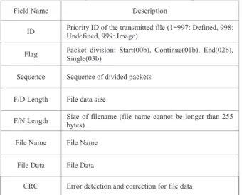
Table 5 Flag information of flexible packet
Field Name Description
ID Priority ID of the transmitted file (1~997: Defined, 998:
Undefined, 999: Image)
Flag Packet division: Start(00b), Continue(01b), End(02b), Single(03b)
Sequence Sequence of divided packets
F/D Length File data size
F/N Length Size of filename (file name cannot be longer than 255 bytes)
File Name File Name
File Data File Data
CRC Error detection and correction for file data
However, to transmit multiple files using the same packets, waiting time is generated in order to wait for the transmission frames for the number of files. It, therefore, takes a long time to send all the data. To solve this problem, all packets are designed as flexible packets based on the fixed frame as shown in Table 4. This method can transmit data faster than the fixed packet method.
Flexible packets were designed based on the preamble field, type (length) field, data field, and cyclic redundancy check field, excluding the destination and origin in the Ethernet protocol (IEEE 802.3).
Table 6 Flexible packet length (Kbytes)
ID File Packet
Length Data Size Packet
Count Remark
1 A-1 100 120 2 0~999
2 F-1 250 1,700 7 1,000~2,999
3 K-1 500 3,000 6 3,000~4,999
4 D-1 1,000 8,000 8 5,000~
5 S-1 Flex. 34,500 Flex. Flex.
The flexible packet (Ⓐ) is composed of multiple packets based on 4 bytes of start and 4 bytes of end. Each packet was divided into Start (ⒷⒷ-①①), Continue (ⒷⒷ-②②), End (ⒷⒷ-③③), and Stand Alone (ⒷⒷ-④④). If the data size is large, the data are sent using the Start, Continue, and End packets.
Table 7 Flexible packet design for data interface (Kbytes)
Minor Frame
Fixed M/F No.
1 2 3 4 5 6 7 8 9 22 23 24 Total Size (Kbytes) Ga Na Da Ra Ma Ba Sa Ah Ja Cha Ka Ta
1 01 A-1
(120) B-1
(30) C-1
(30) D-1
(8,000) E-1 (8,000) F-1
(1,700) G-1
(1,700) H-1
(250) I-1
(7,900) U-1
(100) T-1
(5,000) SI-1
(7,170) 40,000 2 02 A-2
(10) B-2
(30) C-2
(10) D-2
(300) E-2
(200) F-2
(10) G-2
(230) H-2
(250) I-2
(9,000) U-2
(100) T-2
(5,000) SI-2
(24,860) 40,000 3 03 A-3
(10) B-3
(30) C-3
(10) D-3
(8,000) E-3
(2,000) H-3
(250) I-3
(8,500) J-1 (5,000) K-1
(9,000) U-3
(40) T-3
(5,000) SI-3
(2,160) 40,000 4 04 A-4
(10) B-4
(30) D-4
(8,000) E-4
(200) H-4
(250) J-2
(9,500) K-2 (9,000)
L-1(1) (1,100) M-1(1)
(1,500) U-4 (8,000) T-4
(0) SI-4
(2,410) 40,000 5 05 A-5
(10) B-5
(30) H-5
(250) J-3
(9,200) K-3 (4,000)
L-1(2) (8,000) M-1(2)
(6,000) N-1
(150) O-1
(950) U-5
(900) T-5
(5,000) SI-5
(5,510) 40,000 6 06 A-6
(10) H-6
(250) J-4
(3,000) K-4 (3,000) L-2
(9,700) M-2
(10) N-2
(1,500) O-2
(10) U-6
(500) T-6
(5,000) SI-6
(22,210) 40,000
7 07 H-7
(250) L-3
(4,500) M-3
(20) N-3
(2,500) O-3
(10) U-7
(500) T-7
(5,000) SI-7
(32,220) 40,000
8 08 H-8
(250) M-4
(10) N-4
(250) O-4
(3,000) U-8 (3,500) T-8
(5,000) SI-8
(27,990) 40,000
9 09 H-9 (9,600) M-5
(10) N-5
(10) O-5
(3,500) U-9 (8,000) T-9
(0) SI-9
(18,880) 40,000
10 10 M-6
(10) N-6
(3,000) O-6 (10) U-10
(8,000) T-10
(0) SI-10
(28,980) 40,000
11 11 M-7
(3,500) N-7
(300) U_13
(3,200) T-11
(0) SI-11
(33,000) 40,000
12 12 M-8
(10) N-8
(150) U-12
(9,500) T-12
(0) SI-12
(30,840) 40,000
13 13 N-9
(1,800) U-13 (1,000) T-13
(5,000) SI-13
(32,200) 40,000
14 14 U-14
(3,000) U-14
(5,000) SI-14
(32,200) 40,000
15 15 U-15
(2,500) U-15
(5,000) SI-15
(32,500) 40,000
16 01 SI-1
(40,000) 40,000
17 02 SI-2
(40,000) 40,000
18 03 ... 40,000
Table 5 shows the flag definition for running flexible packets.
The priority was given based on the fixed packet design presented in Table 2. For example, the flexible packets were designed to give priority sequentially from “A-1” of minor frame 1. When data are loaded in each minor frame, one file was divided in accordance with the packet size, and the total number of packets can be checked by Packet Sequence. Thus, data can be sent by single or multiple packets.
The packet lengths were defined as 100, 250, 500, 1,000, and Flexible as shown in Table 6. When data to be transmitted are input from a client PC, Packet Length and Packet Counter are generated by analyzing the data size. For example, if the
“A-1” file is input, the file size can be determined to be 120 Kbytes through file size analysis. Since this corresponds to Packet ID #1, when the Packet Length of 100 Kbytes is applied, it is divided into two packets. Thus, two packets are
generated and transmitted by assigning a unique Packet Count to each packet.
Table 7 shows the data transfer method by applying flexible packets based on Table 2. It can be seen that the packet size to be transmitted is smaller compared to Table 2. This is because only the Header and CRC are included after removing the data margin. Furthermore, the packet can be divided into Start (00b), Continue (01b), End (10b), and Single (11b) based on the flag in Table 4. The Packet Count is determined by the Flexible Packet Length presented in Table 6. The ICP related files (green) of the ICPS system in the minor frame 1 in Table 2 are allocated to packet 1 in Table 7 according to the priority.
Then, each time the minor frame is increased, the H-7 (violet), M-6, and N-9 (blue) files are transmitted to the positions of the files that have been transmitted. As a result, only the satellite image data is transmitted from the minor frame no. 16.
4.5 Data transfer by applying designed flexible packets
Fig. 7 describes the data transfer method using flexible packets presented in Table 7. In each system, data are sent to the client PC for data transfer. It is delivered to a specific directory in the server through the inter-network data transfer system. Then, the server transmits data to the system that requests the data through FTP. It was predicted that data transmission efficiency would be improved because flexible packets are used, which allows data transmission according to priority.
As shown in Fig. 8, the test-bed was configured with a server (①) and a client (②) for flexible packet data transmission and a network switch (③) that can provide 40 Mbytes of transmission bandwidth. In this test, the data were sent from the client to the server using flexible packets containing data of up to 12.4 Gbytes (④). This includes 12 Gbytes of satellite image data and telemetry, which is obtained by real-time communication with one Arirang satellite.
Fig. 7 Data transfer method with flexible packets
Fig. 8 Test-bed for data interface
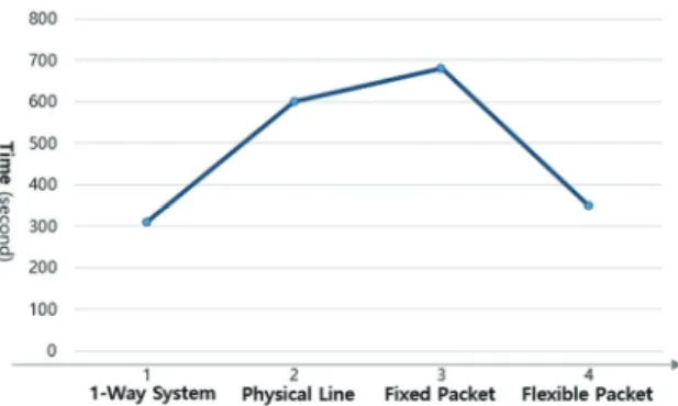
Fig. 9 shows the result of the data transmission test. It can be seen that it took approximately 309 s when a one-way system was used. When only the large image data were sent through another sub-channel, it took approximately 600 s, and when the data were sent using flexible packets, it took approximately 680 s. Finally, when the data were sent using flexible packets, it took approximately 350 s. However, it could be confirmed that approximately 30 s was required to read and analyze the data and approximately 320 s was required to send the data. Depending on the size of the input data, the transmission time ranged from 345 to 335 s.
Consequently, although fixed packets were designed to improve the efficiency of inter-network data transfer after network separation for strengthening the security environment, the total data transmission time increased more than twice and the system had to wait for the fixed packets in the case of ICP/GGS, which generate multiple files. To solve these problems, flexible packets were used, and it was found that compared to the fixed packets, the transmission speed increased by approximately 1.9 times. The achieved transmission speeds were similar to that of the physical inter- network system configuration method.
Fig. 9 Test result of data transmission
6. Conclusions
The Act on the Protection of Information and Communications Infrastructure was enacted in 2001 to protect major information and communication infrastructure facilities from electronic infringements. The designated major information and communication infrastructure facilities must periodically analyze and assess vulnerabilities in order to protect these facilities from vulnerabilities. Furthermore, although network separation is performed for safer network configuration, there are many problems that are left unaddressed even when secure USB memories are used, e.g., the exchange of data infected by malware and intentional data leakage by insiders. To solve these problems, we performed inter-network data transfer using a bidirectional inter-network
data transfer system that only operates in the physical layer and network layer. However, only one file can be transmitted at any one time during inter-network data transfer. To overcome this limitation, we used physical separation of the transmission bandwidth and data transfer using fixed packets.
Data transfer using flexible packets was found to be the most efficient method. Therefore, we designed Start, Continue, End, Single Packets based on the priorities used for the fixed packet design. Data to be received was defined using the Packet Sequence Counter.
This study demonstrated that using the bidirectional inter- network data transfer system and flexible packets, high priority data could be transmitted efficiently even when transmitting large files such as satellite images. The transmission time could also be reduced to a great extent.
Based on the results of this study, we will build an actual system for inter-network data transfer and continue to improve its operational efficiency.
Acknowledgment
This work was supported by the “National Satellite Integration System Development” project of the Korea Aerospace Research Institute.
References
[1] J. H. Han et al., “Secure File Transfer Method and Forensic Readiness by converting file format in Network Segmentation Environment,” Journal of The Korea Institute of Information Security & Cryptology, vol. 29, no.
4, Aug, 2019.
[2] Product Descriptions of Industrial Control System Security at NNSP (Next Network Security Provider), homepage, https://nnsp.co.kr, accessed on Mar, 2020.
[3] Books, The 7th Information Security of a series of Key Information and Communication Technology at Samsung SDS Technical Society, Hanulmplus, 2019.
[4] Information Security Engineer Cafe homepage, https://cafe.daum.net/Security-n01, accessed on Apr 2020.
[5] J. S. Lee, “A Study on Designating the Solution for Deployment of an Efficient Partitioned Network,“ Graduate a Master’s Degree of Dankook University, Jun, 2013
[6] S. H. Lee, “A Study on Separate Plan of Efficient Information System Network in Partitioned Network Environment,“ Graduate a Master’s Degree of Soongsil University, Jun, 2011.
[7] H. J. Jin, “Attack and Defense Modeling and Security analysis of a Network-separated System using Security USB,“ Graduate a Master’s Degree of Korea Aerospace University, Dec, 2014.
[8] K. H. Kim et al., “Reply-Type based Agent Generation of
Legacy Service on One-way data transfer system,”
Journal of the Korea Institute of Information Security &
Cryptology, vol. 23, no. 2. pp. 299-305, 2013.
![Fig. 1 Cybersecurity incidents [2]](https://thumb-ap.123doks.com/thumbv2/123dokinfo/5101130.326569/2.892.467.805.293.502/fig-cybersecurity-incidents.webp)