ISSN:1226-7244 (Print)
ISSN:2288-243X (Online) j.inst.Korean.electr.electron.eng.Vol.22,No.2,506∼509,June 2018 논문번호 18-02-41 http://dx.doi.org/10.7471/ikeee.2018.22.2.506 280
(506)
전장 시스템의 전자파 적합성 대응 기술
Compliance Technologies of Electromagnetic Compatibility in Automotive Electronic Systems
신 영 산
*
, 이 성 수* ★
Youngsan Shin*
, Seongsoo Lee* ★
Abstract
Recently, number of components and operation frequency rapidly increase in automotive systems. This often leads to EMI (electromagnetic interference) where automotive systems suffer from malfunctions induced by electromagnetic wave. This paper surveys various EMC (electromagnetic compatibility) compliance technologies such as EMI filter, EMI shielding materials, and spread spectrum clock generator. Their pros and cons are also explained.
요 약
최근 전장 시스템에서 부품의 개수와 주파수가 급증함에 따라 전자파에 의해 오동작이 발생하는 전자파 간섭 (EMI: electromagnetic interference)이 자주 발생하고 있다. 본 논문에서는 EMI 필터, EMI 차폐 물질, 분산 스펙트 럼 클록 등 다양한 전자파 적합성(EMC: electromagnetic compatibility) 대응 기술을 살펴보고 각 기술의 장단점에 대해 설명한다.
Key words : Automotive, EMC, EMI Filter, EMI Shielding Material, Spread Spectrum Clock
* School of Electronic Engineering and Research Institute of Future Automobile, Soongsil University
★
Corresponding author (e-mail: [email protected], tel: 02-820-0692)
※ Acknowledgment
This research was supported by the MOTIE(Ministry of Trade, Industry & Energy) (10080649) and KSRC(Korea Semiconductor Research Consortium) support program for the development of the future semiconductor device.
Manuscript received Mar. 2, 2018; revised Mar. 21, 2018; Accepted Mar. 22, 2018
This is an Open-Access article distributed under the terms of the Creative Commons Attribution Non-Commercial License (http://creativecommons.org/licenses/by-nc/3.0) which permits unrestricted non-commercial use, distribution, and reproduction in any medium, provided the original work is properly cited.
Ⅰ. 서론
세계 각국에서 자동차의 배기가스나 연비에 대 한 규제를 점점 강화하고 있다. 이를 개선하기 위 해 기존의 기계식 제어 시스템에서 가볍고 효율 이 좋은 전자 제어 시스템으로 바뀌고 있다[1],[2].
또한 반도체 기술이 발전하면서 전자 주행 안정 장치(ESP: electronic stability control)나 지능형 운전자 보조 시스템(ADAS: advanced driver
assistance system)과 같은 안전 시스템의 탑재도 늘고 있다. 이로 인해 자동차에서 반도체 부품의 비율이 증가하였으며, 동작 신뢰성과 안전성의 증 명이라는 새로운 문제를 만들어내었다. 자동차에 서 오동작이 발생하게 되면 심각한 인명 피해가 발생하기 때문이다. 이러한 주요 원인으로 전자파 간섭(EMI: electromagnetic interference)이 있다.
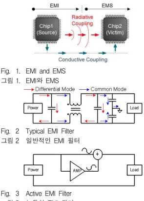
그림 1과 같이 반도체 칩의 동작은 전압이나
전류의 변화를 가져온다. 이 변화는 전자기파
Compliance Technologies of Electromagnetic Compatibility 281 in Automotive Electronic Systems
(507) Fig. 1. EMI and EMS
그림 1. EMI와 EMS
Fig. 2 Typical EMI Filter 그림 2 일반적인 EMI 필터
Fig. 3 Active EMI Filter 그림 3 능동형 EMI 필터
형태로 공간 또는 전송선로를 통해 방사되며, 인 접한 전송선로에 커플링(coupling)되어 다른 칩에 전자기적 에너지로 전달된다. 전달된 에너지는 전 압 또는 전류 노이즈(noise)로 작용하게 되고 다 른 신호에 왜곡을 주어 오동작을 유발한다[3]-[7].
전장 시스템 및 부품은 EMI 수준을 낮추어 다 른 시스템에 영향을 주지 않아야 하며, 동시에 다 른 시스템으로부터의 EMI에도 오동작하지 않는 전자파 내성(EMS: electromagnetic susceptibility) 이 요구된다. EMI와 EMS를 합쳐 전자파 적합성 (EMC: electromagnetic compliance)이라고 한다.
국제 무선 장애 특별위원회(CISPR: International Special Committee on Radio Interference)에서는 CISPR 25[8]와 같은 국제 표준을 제정하여 주파 수 범위에 따른 EMI 수준 제한을 규정하고 있다.
전장 시스템을 개발하는 업체는 EMC를 필수적으 로 고려해야 하므로 많은 회사들이 보드 수준이 나 칩 수준에서의 EMC 대응 기술에 대한 많은 연구를 진행하고 있다.
Ⅱ. 보드 수준에서의 EMC 대응 기술
보드 수준에서의 EMC 대응 기술은 EMI 필터 [9],[10]가 대표적이다. EMI 필터는 등가적으로 L과
C와 같은 수동소자로 구성된 필터이며, EMI 성분 을 노이즈에 강한 전원단으로 우회(bypass)시키거 나 수동 소자의 열손실로 소비시킨다[9]. 수동 소자의 연결에 따라 그림 2와 같이 공통모드 노이 즈나 차동모드 노이즈를 저감시킨다.
EMI 필터를 이용하여 저주파수의 EMI를 저감 하기 위해서는 큰 값을 갖는 L과 C가 필요하다.
수동소자의 값이 부품의 크기에 비례하기 때문에 L과 C가 커지면 부품이 커지는 단점이 있으며 [10] 추가 부품으로 인해 비용도 증가한다.
이러한 단점 때문에 최근에는 그림 3과 같은 능동형 EMI 필터[10]가 연구되고 있다. 능동형 소 자인 OP-AMP에서 입력 노이즈에 대해 반대 위 상의 신호를 생성하여 상쇄시킨다. L과 C 값이 같을 때 OP-AMP의 대역폭 내 주파수에서는 수동형 EMI 필터에 비해 노이즈 저감이 뛰어나다.
그러나 EMI 필터는 근본적인 EMI의 발생 원인 을 줄이는 것이 아니고 보드 상에서의 전도성 EMI만을 저감시키기 때문에 칩 또는 전송선로에 서 공간에 방사된 EMI가 다시 커플링 되거나 EMI 필터 이전에 커플링 되어 나타나는 EMI에 대해서는 저감시키지 못한다.
이를 해결하기 위해 EMI 차폐 물질을 칩이나 모듈에 씌워서 EMI를 저감시키는 방법[11]-[13]
이 있다. EMI 차폐 물질은 공간상에 방사되는 EMI를 흡수하여 열로 방출하거나 접지로 그 전류 를 이동시켜 차단하는 방법이다[14]. 다만 EMI 필터보다 많은 비용이 필요하다는 단점이 있다.
Ⅲ. 칩 수준에서의 EMC 대응 기술
칩의 동작 주파수와 소비 전력이 높아짐에 따라 칩 수준의 EMI도 큰 문제가 되고 있다[14]. 칩 수준에서 대표적인 EMI 저감 기법으로 그림 4와 같이 분산 스펙트럼 클록(SSC: spread spectrum clock)[15]-[18]을 사용하는 방법이 있다. EMI는 전류 소모의 주기에 해당되는 주파수와 그 고조파 에서 발생하기 때문에 클록의 주파수를 시간에 따라 조금씩 분산시키면 EMI 스펙트럼도 여러 주파수에 분산되어 발생한다. 이러한 분산 효과는 그림 5와 같이 고주파로 갈수록 그 효과가 크기 때문에 더 많은 EMI 저감 효과를 얻을 수 있다.
SSC 구현은 그림 6처럼 위상 고정 루프(PLL:
phase locked loop)의 기준 입력 클록을 변조하거나,
282 j.inst.Korean.electr.electron.eng.Vol.22,No.2,506∼509,June 2018
(508) Fig. 4 EMI reduction of SSC [15]
그림 4 SSC의 EMI 저감 효과[15]
Fig. 6 Examples of SSC implementations [15]: (a) modulation of input clock, (b) modulation of VCO input voltage, and (c) modulation of dividing ratio
Fig. 5 EMI reduction of SSC at harmonic frequency [16]
그림 5 고조파에서 SSC의 EMI 저감 효과[16]
그림 6 SSC의 구현 예[15]: (a) 입력 클록 변조, (b) VCO 입력 전압 변조, (c) 분주비 변조
전압 제어 발진기(VCO: voltage controlled oscillator) 의 입력 전압을 변조하거나, 분주기(divider)의 분주비 를 변조하는 방법이 있다.
SSC를 이용한 EMI 저감 기법은 칩 내부 회로 에서 EMI를 저감하기 때문에 EMI 필터나 EMI 차폐 물질에 비해 무게나 부피 면에서 큰 장점이 있다. 추가 회로로 인한 비용도 더 작다.
SSC를 사용하는 경우에 시스템의 동작 관점에 서 다음의 문제점이 있다. 첫 번째로 아날로그-디 지털 변환기(ADC: analog-to-digital converter)에 서 SSC로 인한 샘플링 주파수의 변조는 ADC에 서 클록 지터(clock jitter)로 작용하는 문제가 있다[19]. 클록 지터는 샘플링된 신호에 노이즈로 작용하며, 더 많은 EMI를 저감시키기 위해 SSC의 변조폭을 늘릴 경우 지터 크기가 증가한다. ADC 의 샘플링 전압에 인가된 노이즈는 ADC의 주요 성능 지표인 신호 대 잡음+왜곡 비(SNDR:
sinal-to-noise+distortion ratio)를 저하시킨다.
두 번째로 샘플링된 신로를 디지털 필터로 처리 하는 경우 전달 특성을 변화시키는 문제가 있다.
디지털 필터를 설계할 때, ADC의 샘플링 주기를 기준으로 각 계수 값들이 결정된다. 따라서 SSC 로 인해 샘플링 주기가 바뀐다면 디지털 필터의
전달 특성이 변화하는 문제점이 생긴다[20].
마지막으로 디지털 인터페이스에서 타이밍 에 러에 대한 문제가 있다[7]. 디지털 인터페이스는 일반적으로 클록 기준으로 데이터를 읽어오기 때 문에 SSC로 인한 클록 주파수의 변화는 전송된 데이터의 에러를 유발한다.
따라서 SSC로 인한 오동작을 막기 위해 SSC 의 변조 폭에 대한 제한치를 두거나 일부 회로에 만 적용해야 한다. 이로 인해 저감할 수 있는 EMI 크기에도 한계가 존재한다.
Ⅳ. 결론
전장 시스템에서 반도체 부품의 증가는 EMC
국제 규정의 만족하는 EMC 대응 기술을 절실히
필요로 하고 있으며, 본 논문에서는 칩 수준 또는
보드 수준에서의 다양한 EMC 대응 기술을 살펴
보았다. 하지만 아직까지 복잡한 시스템에서 EMI
발생량이나 커플링 경로가 명확하게 파악되지
못하여, EMC 대응 기술은 축적된 노하우를 통한
해결 방식이 주를 이룬다. 따라서 향후 EMC 예측
기술에 대한 연구가 필요할 것으로 예상된다.
Compliance Technologies of Electromagnetic Compatibility 283 in Automotive Electronic Systems
(509)
References
![그림 4 SSC의 EMI 저감 효과[15]](https://thumb-ap.123doks.com/thumbv2/123dokinfo/4670521.500269/3.892.85.815.149.634/그림-ssc의-emi-저감-효과.webp)
