N-pole 종류의 FSS가 결합된 복합재료 구조의 잔류응력과 전파투과특성
박 경 미1․황 인 한1․전 흥 재1†․홍 익 표2․박 용 배3․김 윤 재4
1연세대학교 기계공학과, 2공주대학교 정보통신공학부, 3아주대학교 전자공학과, 4국방과학연구소
Study on Thermal Residual Stresses and Transmission Characteristics in N-pole Type Frequency Selective Surface
Embedded Composite Structures
Kyoung Mi Park1, In Han Hwang1, Heoung Jae Chun1†, Ic Pyo Hong2, Yong Bae Park2 and Yoon Jae Kim4
1School of Mechanical Engineering, Yonsei University, Seoul, 120-749, Korea
2School of Information Communication Engineering, Kongju National University, Cheonan, 330-717, Korea
3School of Electrical and Computer Engineering, Ajoo University, Suwon, 443-749, Korea
4Agency for defense development, Daejeon, 305-152, Korea
Abstract
In this paper, the delamination and failures in frequency selected surface(FSS) caused by residual stresses in the FSS embedded hybrid composites due to the difference between the coefficients of thermal expansion of components and the transmission characteristic changes due to deformation of FSS patterns by residual stresses were studied. FSS may have different electromagnetic characteristics depending on the type of element, design variables, and arrangement. Design variables of dipole FSS were determined using PSO(Particle Swarm Optimization) to obtain the transmission characteristic for the target resonant frequency. Subsequently, the design variables of other types of N-pole(tripole, cross dipole, and Jerusalem cross) were determined based on the dimensions of the dipole for the comparisons of residual stresses of FSS embedded composite structures and transmission characteristics. In addition, effects of FSS pattern, and stacking sequence of composite laminates were considered.
Keywords : frequency selective surface, residual stress, transmission characteristics
†Corresponding author:
Tel: +82-2-2123-4827; E-mail: [email protected] Received December 11 2012; Revised March 5 2013;
Accepted March 5 2013
Ⓒ 2013 by Computational Structural Engineering Institute of Korea
This is an Open-Access article distributed under the terms of the Creative Commons Attribution Non-Commercial License(http://creativecommons.
org/licenses/by-nc/3.0) which permits unrestricted non-commercial use, distribution, and reproduction in any medium, provided the original work is properly cited.
1. 서 론
섬유강화 복합재료는 비강도 및 비강성이 기존에 많이 이용 되는 철이나 알루미늄 등의 단일재료에 비해 크게 높고 우수한 피로특성 및 치수안정성 등의 재료 특성을 지녀, 고성능을 요 구하는 우주항공, 자동차 등의 산업에서 널리 사용되고 있으 며, 그 중 유리섬유는 기계적, 전자기적 특성이 뛰어나 레이더 의 외부 열, 기계적인 충격 등으로부터 보호하는 레이돔 (Radome)의 재료로 쓰인다. 레이더는 송신부에서 보낸 전자 기파가 표적에서 반사되어 수신안테나에 감지되어 표적의 거
리와 위치를 알아내는 장치이다. 전자기파에 탐지되는 정도를 나타내는 Radar Cross Section(RCS) 감소기술은 스텔스 기술의 한 분야로 국방분야에서 항공기, 미사일, 전함과 같은 무기체계의 생존성을 좌우하는 핵심기술 분야로 인식되고 있 다(Jenn, 1991). 따라서 입사되는 특정대역의 전자기파를 투 과시킬 수 있는 주파수 선택 기능을 레이돔에 적용하여, 기존 의 레이돔에 전자기파를 선택적으로 투과 또는 반사시킬 수 있 는 주파수 선택적 투과구조(Frequency Selective Surface:
FSS)의 기능을 적용한 하이브리드 레이돔의 개발이 필요하다.
하이브리드 레이돔은 FSS와 복합재료로 구성되어 적의 탐지
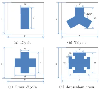
(a) Dipole (b) Tripole
(c) Cross dipole (d) Jerusalem cross Fig. 2 N-pole FSS of unit cells
Fig. 1 Dipole FSS and design parameters
Parameters x y w d
Initial value(mm) 9 10 2 7.2
Table 1 Values of design parameters for dipole FSS
Fig. 3 3D model of dipole FSS embedded hybrid composites
레이더로부터 입사하는 전자기파를 흡수하며 구조적으로 안전 하다는 장점을 가지고 있어 각국에서 활발히 연구되었다 (Chen et al., 2008; Wahid et al., 1991; Munk, 2000).
국내는 Dipole slot의 배열주기와 길이, 폭 변화가 FSS의 전 자기파 투과 특성에 미치는 영향과 하이브리드 레이돔의 구성 재료간의 접합능력을 향상시키는 방법이 연구되었다(Kim et al., 2006; 2009). 하이브리드 레이돔의 동시경화과정에서 경화 후 성형온도인 고온에서 상온으로 온도가 내려가면서 재료 간의 열팽창계수 차이로 열 잔류응력이 발생한다. 이러한 열 잔 류응력은 구조적으로 국부 항복을 일으키거나 층간분리 현상을 야기할 수 있다(Lee, 2000). 또한 잔류응력에 따른 구조적 변 화는 전자기파 특성에 영향을 줄 수 있어, Square Loop의 경화 공정에 따른 잔류응력과 복합재료의 층간분리(Delamination) 발생 연구가 수행되었다(Seo et al., 2010; Kim et al., 2011). 하지만, 복합재료 구조의 제작과정에서 발생한 잔류응 력에 의하여 변형된 FSS를 고려한 전파특성 연구는 미비한 실 정이다. 따라서 본 논문은 N-pole 종류의 FSS의 설계치수를 동 일화하고, 이러한 FSS와 E-glass/ epoxy 복합재료로 구성된 하이브리드 레이돔의 동시경화 과정에서 발생하는 잔류응력과 그로 인한 Copper FSS의 파손, 복합재료의 층간분리, 전파특 성을 FSS 단위요소와 복합재료 적층을 변화시켜 비교하였다.
2. 연구대상 및 방법
2.1 FSS 단위요소
FSS의 단위요소는 Jerusalem cross, Square loop, Hexagon element, Ring 등이 있다. 이 중에서 가장 많이 사용되는 Dipole을 기본 요소로 설정하였다(Munk, 2000).
Fig. 1은 Dipole FSS이다.
Dipole FSS는 PSO 알고리즘을 이용하여 FSS가 X-band (8~12GHz)에서 투과특성을 가지도록 설계하였으며, 그 결 과는 Table 1과 같다(Park et al., 2012).
N-pole 종류의 FSS들이 설계치수가 동일할 때 정시 단위 요소 형상이 잔류응력과 전파특성에 미치는 영향을 비교하기 위하여 앞서 설계한 Dipole 설계치수를 Dipole을 제외한 N-pole 종류 단위요소들(Tripole, Cross dipole, Jerusalem cross)에 적용하였다.
Fig. 2는 연구에서 사용된 FSS 단위요소들의 Unit cell 을 나타낸다. Fig. 2(a)는 Dipole, Fig. 2(b)는 Tripole, Fig. 2(c)는 Cross dipole, Fig. 2(d)는 Jerusalem cross 이다.
2.2 하이브리드 복합재료 모델
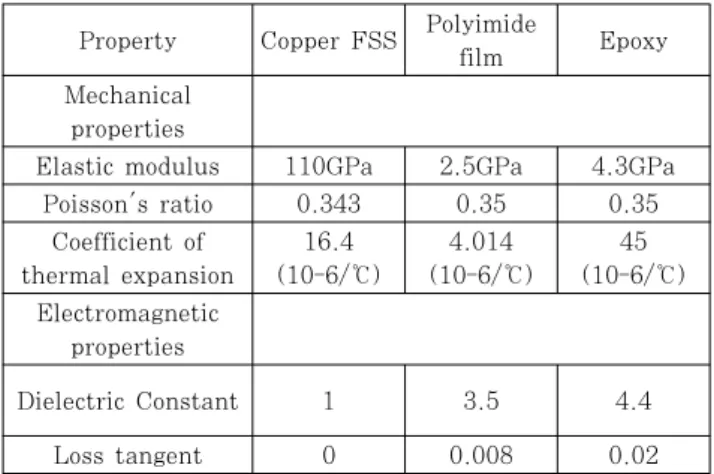
하이브리드 복합재료 모델은 FSS(Copper와 Polyimide film)와 복합재료 유전체 E-glass/epoxy로 구성된다. FSS 에서 Copper의 빈 부분은 Epoxy resin이 채워져 있는 것 으로 가정하였고, FSS의 윗부분과 아래에 복합재료 유전체 를 접합시켰다. 복합재료의 두께는 위와 아래 값이 동일하게 8 ply로 적층하여 1.20mm, Copper foil의 두께는 18μm, Polyimide film의 두께는 40μm이며, UG NX7.0(Siemens PLM Software)으로 3D 모델링하였다. Fig. 3은 Dipole 을 기본요소 가지는 하이브리드 복합재료 모델의 3D Model 이다. 각 구성 재료들의 물성은 Table 2와 Table 3에 정리
Property Copper FSS Polyimide
film Epoxy
Mechanical properties
Elastic modulus 110GPa 2.5GPa 4.3GPa
Poisson's ratio 0.343 0.35 0.35
Coefficient of thermal expansion
16.4 (10-6/℃)
4.014 (10-6/℃)
45 (10-6/℃) Electromagnetic
properties
Dielectric Constant 1 3.5 4.4
Loss tangent 0 0.008 0.02
Table 2 Mechanical and electromagnetic properties of copper FSS, polyimide film and epoxy
Property E-glass/epoxy
Mechanical properties
Longitudinal modulus 38.6GPa
Transverse modulus 8.27GPa
In-plane shear modulus 2.3GPa
Poisson's ratio 0.26
Longitudinal coefficient of thermal expansion 6.3(10-6/℃) Transverse coefficient of thermal expansion 20(10-6/℃)
Transverse tensile strength 65MPa
Out-of-plane shear strength 40MPa
Electromagnetic properties
Dielectric Constant 4.35
Loss tangent 0.0032
Table 3 Mechanical and electromagnetic properties of E-glass/epoxy composite
Fig. 4 Cure cycle used to co-cure E-glass/epoxy composite and FSS embedded hybrid composites
하였다.
2.3 연구방법
2.3.1 구조해석
구조해석 시뮬레이션 ABAQUS 6.10(Dassult Systems SIMULIA, Inc.)을 사용하여 FSS가 삽입된 하이브리드 복
합재료의 잔류응력 및 그에 의한 FSS 변형을 예측하였다.
각 구성 요소는 솔리드 요소로 가정하였으며, 적층에 따른 영향을 확인하기 위하여 5가지 적층([0]8, [90]8, [0/90]4, [±45]4, [0/±45/90]2)을 가진 복합재료 유전체를 생성하였 다. 경계조건은 이를 고려하여 축 방향에 대하여 대칭 조건 을 사용하였고, 자유로운 팽창 및 수축이 가능하도록 복합재 료 유전체 하단의 축만을 고정시켰다. 하중조건은 경화가 된 이후, 상온으로 냉각되는 과정을 가정하기 위하여 Fig. 4 의 E-glass/epoxy 복합재의 경화 사이클에서와 같이 경화온 도인 120℃에서 상온(25℃)이 되도록 설정하였다.
2.3.2 전자기장해석
HFSS 13(Ansys Corporation)을 이용하여 E-glass/
epoxy 복합재 사이에 FSS가 결합된 하이브리드 복합재료 모델의 전파 투과특성을 예측하였다. 또한 하이브리드 모델 이 잔류응력으로 인하여 FSS 단위요소가 변형되었을때 전파 투과특성을 비교하기 위해 각 FSS 단위요소에 대하여 복합 재의 적층에 따른 FSS가 변형된 경우를 고려하였다.
전자기장해석에 사용된 모델을 Fig. 5에 나타내었다. 하이 브리드 복합재료를 거쳐 자유 공간으로 복사되는 전파의 패 턴을 확인하기 위해 경계면의 매질을 공기로 선택하였다.
Fig. 5 Electromagnetic simulation model
2.4 복합재료 층간분리 파손기준
E-glass/epoxy 복합재료의 층간분리 파손을 위하여 식 (1)과 같이 Delamination. Failure. Index.(D.F.I.)를 사 용하였다(Chun et al., 2011). D.F.I. 값이 1을 넘으면 층 간분리가 발생한다고 가정하였다.
33 33 13
33
3 3 13
13 13 33
13 13 3
, ( 0) . . .
,
T T
T
F when F F
D F I
F when F F
σ σ σ σ
σ σ σ
⎧ > >
= ⎨⎪⎪
⎪ >
⎪⎩
(1)
식 (1)에서 과 은 층간 응력을, 와 은 각각 면외 인장강도와 전단강도를 나타낸다.
Stacking sequence
Maximum Von Mises stress
(MPa) D.F.I.
Copper Polyimide Epoxy Composite
[0]8 28.2 6.274 6.341 0.015
[90]8 29.5 6.265 6.308 0.015
[0/90]4 14.8 5.555 6.163 0.048
[±45]4 14.4 6.174 8.494 0.054
[0/±45/90]2 14.7 5.973 6.586 0.055 Table 4 Residual stresses of epoxy, polyimide, copper of dipole(MPa) and D.F.I. of e-glass/epoxy composite
Fig. 6 Maximum Von Mises stress distribution of unit cell of dipole copper([90]8)
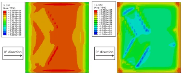
Fig. 7 Maximum out-of-plane residual stress distributions(and ) of composite layer at the
interface between FSSs in dipole FSS embedded hybrid composites([0/±45/90]2)
Stacking sequence
Maximum Von Mises stress
(MPa) D.F.I.
Copper Polyimide Epoxy Composite
[0]8 35.7 7.151 6.360 0.015
[90]8 32.8 6.640 6.340 0.015
[0/90]4 16.7 5.427 6.039 0.048
[±45]4 17.3 5.671 7.241 0.054
[0/±45/90]2 18.7 6.733 6.355 0.055 Table 5 Residual stresses of epoxy, polyimide, copper of tripole(MPa) and D.F.I. of e-glass/epoxy composite
Fig. 8 Maximum Von Mises stress distribution of unit cell of tripole copper([0]8)
Fig. 9 Maximum out-of-plane residual stress distributions( and ) of composite layer at the
interface between FSSs in tripole FSS embedded hybrid composites([0/±45/90]2)
3. 결 과
3.1 구조해석 결과
하이브리드 복합재료 구조에서 발생하는 잔류응력과 그로 인한 Copper FSS의 파손, 복합재료의 층간분리현상을 확인 하기 위하여 N-pole 종류의 FSS 단위요소에 대하여 구조해 석을 수행하였다.
Table 4는 Dipole의 FSS가 결합된 복합재료 구조에서 Copper FSS, Polyimide, Epoxy의 등가 응력 결과와 E-glass/
epoxy 복합재료와 FSS의 경계면에서 E-glass/epoxy 복합재 료의 D.F.I. 값이다. Table에서 보이듯이 Copper FSS의 등가 응력은 해석에서 고려된 [0]8, [90]8, [0/90]4, [±45]4, [0/±45/90]2 적층에서 Copper의 강도(350MPa)보다 낮은 값을 보여 Copper FSS의 파손가능성이 낮음을 확인하였다. 가 장 높은 값을 보인 [90]8 적층인 경우의 응력분포는 Fig. 6과
같다. 또한 E-glass/epoxy 복합재료의 D.F.I. 값은 [0/±
45/90]2 적층에서 최댓값 0.055를 나타냈으며, D.F.I. 값이 가장 높은 [0/±45/90]2 적층의 층간응력(, )분포는 Fig.
7과 같다. Dipole FSS의 형태의 해석에 고려된 복합재료의 적 층에 대하여 E-glass/epoxy 복합재료의 D.F.I. 값이 1에 도달 하지 않으므로 복합재료 간의 층간분리현상이 발생할 가능성은 낮다.
Table 5는 Tripole 모델에서 Copper FSS, Polyimide 필름, Epoxy 수지의 등가응력 결과와 복합재료의 D.F.I. 값 이다. Copper의 잔류응력은 [0]8, [90]8, [0/90]4, [±45]4, [0/±45/90]2 적층에서 강도보다 낮은 값을 보여 파손 발생의 가능성이 낮음을 보여주며, E-glass/epoxy 복합재료의 D.F.I.
값은 1을 넘지 않아 층간분리가 발생하지 않았음을 확인하였 다. 또한 E-glass/epoxy은 [0/±45/90]2 모델에서 최대
Stacking sequence
Maximum Von Mises stress
(MPa) D.F.I.
Copper Polyimide Epoxy Composite
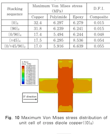
[0]8 32.4 6.297 6.279 0.015
[90]8 31.8 6.239 6.241 0.015
[0/90]4 17.4 5.494 6.244 0.048
[±45]4 17.5 6.295 8.536 0.054
[0/±45/90]2 17.0 5.916 6.639 0.055 Table 6 Residual stresses of epoxy, polyimide, copper
of cross dipole(MPa) and D.F.I. of e-glass/epoxy composite
Fig. 10 Maximum Von Mises stress distribution of unit cell of cross dipole copper([0]8)
Fig. 11 Maximum out-of-plane residual stress distributions( and ) of composite layer at the
interface between FSSs in cross dipole FSS embedded hybrid composites([0/±45/90]2)
Stacking sequence
Maximum Von Mises stress
(MPa) D.F.I.
Copper Polyimide Epoxy Composite
[0]8 33.3 6.892 6.994 0.016
[90]8 31.9 6.760 6.878 0.016
[0/90]4 13.7 6.021 6.503 0.046
[±45]4 14.1 6.552 8.792 0.052
[0/±45/90]2 13.7 6.712 6.898 0.052 Table 7 Residual stresses of epoxy, polyimide, copper of Jerusalem cross(MPa) and D.F.I. of e-glass/epoxy
composite
Fig. 12 Maximum Von Mises stress distribution of unit cell of Jerusalem cross copper([0]8)
Fig. 13 Maximum out-of-plane residual stress distributions( and ) of composite layer at the
interface between FSSs in Jerusalem cross FSS embedded hybrid composites([0/±45/90]2) D.F.I. 값 0.055를 보였는데, 이 값은 작은 값으로 층간분리
의 가능성이 낮고, 따라서 잔류응력이 복합재료의 강도에 영향 이 작음을 확인할 수 있었다. Copper FSS에서 가장 높은 잔 류 응력을 보인 [0]8 적층 모델의 응력분포는 Fig. 8과 같으 며, D.F.I. 값이 가장 높은 [0/±45/90]2 모델의 층간응력 (, )분포는 Fig. 9와 같다.
Table 6은 Cross dipole을 적용한 하이브리드 레이돔 모 델의 FSS 구성재료의 등가응력 결과와 E-glass/epoxy 복 합재료의 D.F.I. 값이다. Copper FSS의 잔류응력은 5가지 적층 모델에서 Copper 강도보다 낮은 값을 보였고, [0]8 적 층 모델에서 최대값을 가졌다. 모든 적층의 최대 등가응력이 발생하는 곳에서 파손이 일어나지 않음을 확인하였다. 또한 E-glass/epoxy 복합재료의 D.F.I. 값은 [0/±45/90]2 모델
에서 최대 D.F.I. 값 0.055를 보였다. Copper FSS에서 가장 높은 잔류응력을 보인 [0]8 적층 모델의 잔류응력분포 는 Fig. 10과 같으며, 최대 D.F.I값을 보인 [0/±45/90]2
적층모델의 층간응력(, )분포는 Fig. 11과 같다.
Table 7은 Cross dipole을 변형시킨 Jerusalem cross 모델의 Copper FSS, Polyimide, Epoxy의 등가응력과 E-glass/epoxy와 FSS의 경계면의 D.F.I. 값이다. Jerusalem cross는 Copper FSS와 D.F.I. 값에 대하여 Cross dipole 모델과 유사한 결과를 보였다. [0]8 적층에서 최대 등가응력 값을 가지며, Copper 강도(350MPa)보다 낮아 파손이 발생 하지 않음을 보여주었다. E-glass/epoxy 복합재료의 층간분 리 유무를 판단하는 D.F.I. 값은 모든 모델에서 층간분리가 발생하지 않았으며, [0/±45/90]2모델에서 최대 D.F.I.값
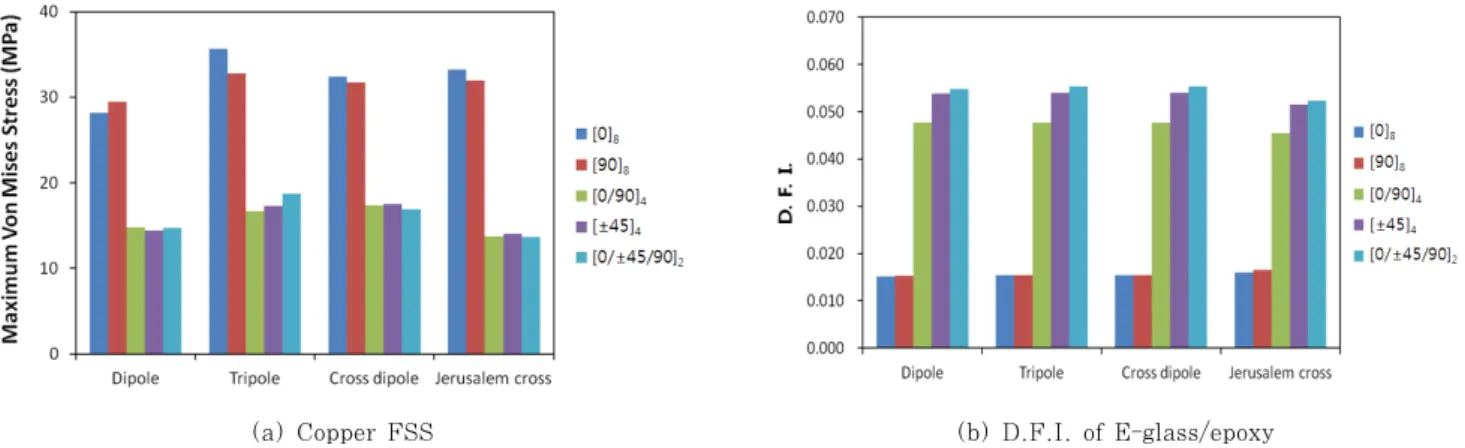
(a) Copper FSS (b) D.F.I. of E-glass/epoxy
Fig. 14 Comparisons of residual stresses and D.F.I. in FSS hybrid composites with different stacking sequences
0.055를 보였다. Jerusalem cross 모델에서 최대 잔류응력 을 보인 [0]8 적층 모델의 잔류응력 분포는 Fig. 12, 최대 D.F.I.를 보인 [0/±45/90]2 적층의 층간응력(, )분포 는 Fig. 13과 같다.
Copper FSS의 등가응력과 E-glass/epoxy의 D.F.I.를 N-pole 종류에 따라서 정리하면 Fig. 14와 같다.
Copper FSS의 등가응력은 모든 N-pole 종류에서 Copper 의 강도보다 낮은 값을 보여 국부적 파손이 발생하지 않음을 확인하였다. 최대 등가응력 값은 Tripole, Cross dipole, Jerusalem cross, Dipole의 순으로 높은 값을 갖는 경향을 나타냈으며, 각각의 종류에 따라 일 방향 적층인 [0]8과 [90]8
적층모델에서 그 외의 적층들보다 높은 값을 보였다. 이에 따 라 등가등력은 단위요소의 종류보다 복합재료 적층에 영향이 높은 것으로 확인되었다. 또한 E-glass/ epoxy 복합재료의 D.F.I.도 FSS의 단위요소 종류보다 복합재료의 적층에 따라 D.F.I. 값이 변하였다. [0/±45/90]2 적층 모델에서 가장 높 은 D.F.I. 값을 보이며, 다른 적층에 비하여 층간분리현상이 발생할 가능성이 높은 것으로 확인되었다.
3.2 전자기장해석 결과 FSS 단위요소
E-glass/epoxy 복합재료 유전체가 포함된 하이브리드 복 합재료 구조는 제작과정에서 발생하는 잔류응력으로 FSS의 패턴의 변형이 일어난다. 따라서 복합재료의 잔류응력에 대 한 복합재료의 적층의 영향성을 확인하기 위하여 구조해석 결과를 반영한 5가지 적층 모델([0]8, [90]8, [0/90]4, [±45]4, [0/±45/90]2)과 잔류응력을 고려하지 않은 설계치 수대로의 초기모델을 Initial 모델이라 정의하고 각 모델에 대하여 공진주파수 결과를 Table 8에 나타내었다.
해석결과의 타당성을 위하여 FSS가 포함된 하이브리드 복 합재료에 대한 선행연구 방법에 따라 해석을 수행하였으며, 선
행연구는 실험에 의하여 결과가 입증되었다(Hwang, 2013).
Fig. 15은 N-pole 종류에 따라서 각각의 하이브리드 복 합재료 구조물의 전파투과특성이 나타나는 공진주파수를 나 타낸 것으로, 4가지 종류의 FSS에서 공진이 발생하는 8~
13GHz 대역에 대하여 표시하였다.
FSS 패턴의 종류에 따라 전타투과특성을 지니는 공진주파 수의 최대 변화량과 변화가 일어나는 적층은 다음과 같다.
Dipole은 초기모델에 비하여 모든적층에서 약0.35GHz 증가 하였으며, Tripole 모델에서는 초기 모델보다 약 0.16GHz 증 가하였다. Cross dipole 모델의 경우, [0/90]4, [0/±45/90]2
적층모델에서 공진주파수의 변화량이 가장 크며, 약 0.37 GHz 증가하였다. Jerusalem cross 모델은 [0/±45/90]2 적 층 모델에서 공진주파수의 변화량이 가장 크며, 변화량은 약 0.35Hz이다.
N-pole 종류의 FSS가 결합된 하이브리드 복합재료 구조 는 Dipole, Cross dipole, Jerusalem cross에서 초기 모 델보다 0.3GHz 이상의 공진주파수 변화가 있지만, Tripole FSS가 결합된 모델에서는 최대 0.15GHz의 변화를 보였다.
또한 각각의 종류에 따른 적층각별 주파수 변화는 크지 않아 서 공진주파수의 변화는 복합재료의 적층보다 FSS 패턴의 형상에 대한 영향성이 큰 것으로 확인되었다.
Stacking sequence
Resonant frequency(GHz) Dipole Tripole Cross
dipole
Jerusalem cross
Initial 10.30 10.49 11.36 9.19
[0]8 10.64 10.64 11.71 9.48
[90]8 10.65 10.65 11.73 9.53
[0/90]4 10.64 10.64 11.74 9.53
[±45]4 10.64 10.65 11.72 9.53
[0/±45/90]2 10.64 10.64 11.74 9.54 Table 8 Resonant frequency of FSS embedded composite
structure effected residual stresses
(a) Dipole (b) Tripole
(c) Cross dipole (d) Jerusalem cross
Fig. 15 Transmission Characteristics of N-pole type FSSs effected residual stresses
4. 결 론
본 논문에서는 설계치수가 동일한 N-pole 종류의 FSS와 복합재료를 접합한 하이브리드 복합재료의 제작 과정에서 발 생할 수 있는 잔류응력을 확인하고, 그에 따른 영향으로 발 생할 수 있는 FSS의 파손여부 및 복합재료의 층간 분리와 FSS의 변형으로 인한 전파 투과특성의 영향을 확인하였고 다음과 같은 결론을 얻었다.
Copper FSS의 등가응력은 N-pole 종류보다 복합재료의 적층에 등가응력 값의 영향을 받았으며, Tripole에서 가장 큰 등가응력이 확인되었고, 해석에 고려된 모든 모델에서 FSS의 국부적 파손은 발생하지 않았다.
복합재료의 D.F.I.는 패턴보다 적층의 영향을 더 크게 받 았으며, 모든 패턴의 [0/±45/90]2 적층 모델에서 가장 높은 값을 보임을 확인하였다. D.F.I.값은 1을 넘지 않아 층간분 리현상은 발생하지 않았다.
FSS에 복합재료 유전체가 결합된 하이브리드 복합재료는 Cross dipole, Tripole, Dipole, Jerusalem cross의 순서 대로 높은 주파수대역에서 공진이 발생하였다. 또한, 잔류응력 에 의한 공진 주파수의 변화는 N-pole 종류에 따라서 Dipole,
Cross dipole, Jerusalem cross 모델에서 0.3GHz 이상의 변화가 일어났으나, Tripole에서 최대 0.15GHz의 변화를 보 여 Tripole이 결합된 하이브리드 복합재료가 공진주파수 변화 에 대하여 가장 안정적이다.
감사의 글
본 연구는 방위사업청과 국방과학연구소가 지원하는 국방 피탐지 감소기술 특화연구센터 사업의 일환으로 수행되었습 니다.
참 고 문 헌
Lee, S.S. (2000) Analysis of Residual Stresses Induced during Adhesion Process of Chip and Leadframe, Journal of the Computational Structural Enginee- ring, 13(1), pp.97~103.
Seo, I.S., Kim, J.K., Choi, I., Lee, D.G. (2010) Effects of Adhesive Properties in FSS embeeded Hybrid Structures, Proceeding of the Korea Institute of Military Science and Technology conference 2010,
요 지
본 논문에서는 주파수 선택적 투과막(FSS)이 결합된 복합재료 구조에서 구성 재료 간의 열팽창계수 차이로 잔류응력이 발생하므로 이로 인한 층간분리나 FSS의 손상 등 구조적인 파손 가능성과 잔류응력으로 인하여 변형된 FSS가 전파투과특 성에 미치는 영향에 대하여 연구하였다. FSS는 단위요소의 종류, 설계변수, 배열에 따라 전파특성이 다르게 나타나므로, PSO 알고리즘을 이용하여 다이폴이 목표주파수에서 투과특성을 갖도록 설계하고 그 설계치수를 다른 N-pole 종류 단위요 소(Tripole, Cross dipole, Jerusalem cross)에 적용하여, 복합재료 구조에 발생하는 잔류응력과 그로인한 구조적 손상과 전파 특성을 영향성을 관찰하고 FSS패턴과 복합재료의 적층 변화에 따라 비교하였다.
핵심용어 : 주파수 선택적 투과막, 잔류응력, 투과특성 pp.36~38.
Kim, K.Y., Kang, K.T., Chun, H.J., Lee, K.Y., Hong, I.P., Lee, M.K. (2011) Thermal Residual Stresses in theFrequency Selective Surface Embedded Composite Structures and Design of Frequency Selective Surface, Journal of the Korean Society for Composite Materials, 24(1), pp.37~44.
Park, K.M., Hwang, I.H., Chun, H.J., Hong, I.P., Park, Y.B., Lee, M.K. (2012) Thermal Residual Stresses in the Frequency Selective Surface Embed- ded Composite Structures and Design of Frequency Selective Surface, Proceeding of the Korea Institute of Military Science and Technology Conference 2012, p.338.
Hwang, I.H. (2013) Study of Mechanical - Electro- magnetic Transmission Characteristics in Frequency Selective Surface Embedded Composite Structures, Master Degree, Yonsei University, pp.1~99.
Chen, H., Hou, X., Deng, L. (2008) Design of Frequency-Selective Surfaces Radome for a Planar Slotted Waveguide Antenna, IEEE Trans, Antennas
and Wireless Propagation Letters, 8(3), pp.1231~
1233.
Jenn, D.C. (1995) Radar and Laser Cross Section Engineering, American Institute Aeronautics and Astronautics Inc., Washington, DC, pp.1~13.
Kim, P.C., Chin, W.S., Lee, D.G., Seo, I.S. (2006) EM Characteristics of the RAS Composed of E-Glass/Epoxy Composite and Single Dipole FSS Element, Journal of Composite Materials, 75, pp.601
~609.
Kim, P.C., Lee, D.G. (2009) Improvement of Bonding Characteristics Between the Frequency Selective Surface and E-glass/epoxy Composite, Journal of Adhesion Science and Technology, 23, pp.215~
227.
Munk, B.A. (2000), Frequency Selective Surfaces : Theory and Design, John Wiley & Sons, Inc., New York.
Wahid, M., Morris, S.B. (1991) Band pass radomes for reduced RCS, IEE Colloquium on Antenna Radar Cross-Section, May 7, pp.4/1~4/4.