• 검색 결과가 없습니다.

Vibration analysis of a DWT 1,000-ton ocean-research vessel with electric propulsion

N/A
N/A
Protected

Academic year: 2021

Share "Vibration analysis of a DWT 1,000-ton ocean-research vessel with electric propulsion"

Copied!
8
0
0

로드 중.... (전체 텍스트 보기)

전체 글

(1)

INTRODUCTION

Current trends indicate that both the size and sailing ve- locity of ships are increasing, which has led to a greater focus on the importance of vibration and noise. Periodic unbal- anced forces in the propulsion system inevitably give rise to vibration, and when the excitation frequency is close to a res- onance frequency of a vibrational mode of the ship, signifi- cant motion of the structure may occur (Nippon Kaiji Kyokai, 1984). Close to resonance, the displacement and ac- celeration of the hull plate may be large, which may lead to serious structural effects for the vessel, as well as comfort issues for the crew and passengers. To avoid this, the struc- ture and propulsion system should be designed to avoid ex- citing the vibrational modes of the vessel (Okumoto et al., 2009).

With the development of power electronics, electric

propulsion systems have become increasingly important, es- pecially for niche applications and military vessels. Electric propulsion systems have significant benefits in terms of mo- bility, reliability, and efficiency, as well as in terms of envi- ronmental sustainability. For these reasons, electric propulsion has the potential to become the dominant method of propulsion for ships in the future (ABS, 2006).

To avoid damage to the vessel and discomfort to the crew and passengers, it is important for engineers to analyze the response to vibration prior to production. The finite element method (FEM) is an effective method for such an analysis, and is a convenient and efficient means of modeling the re- sponse to vibration (Bathe et al., 1996).

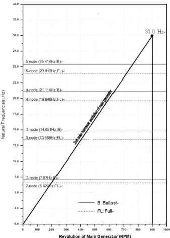
The objective of this paper was to study the vibrations of the hull of a special-purpose vessel with electric propul- sion. We used a three-dimensional (3D) FE model to ana-

Vibration analysis of a DWT 1,000-ton ocean-research vessel with electric propulsion

Dong-Myung BAE*, Bo CAO and Tuo-Han CHEN

1

Dept. of Naval Architecture and Marine Systems Engineering, Pukyong National University, Busan 608-737, Korea

1

Samin information system Co., 1474 CentumSHvalley, U-dong, Haeundae-gu, Busan 612-020, Korea.

In vibration analysis of ships, the principle aim is to determine the natural frequencies and excitation frequencies, and use this information to avoid resonances and vibration damage. The simplest method is to prevent resonance conditions, which is effective as long as the natural frequencies and excitation frequencies can be regarded as independent from environmental conditions.

For ships that use electric propulsion systems, the sources of vibration are reduced compared with those caused by a diesel engine or other combustion-based propulsion systems. However, the frequency spectrum of these vibrations may be different; therefore, to understand the characteristics of the electric propulsion, we also should investigate how the ship responds to these vibrations.

We focused on a 1,000-ton deadweight (DWT) ocean-research vessel using an electric propulsion system and analyzed the re- sponse to vibration.

Keywords : Hull vibration characteristics, Vibration assessment, Electric propulsion, FEM J. Kor. Soc. Fish. Tech., 50 (1), 075-082, 2014

http://dx.doi.org/10.3796/KSFT.2014.50.1.075

*Corresponding author: [email protected], Tel: 82-51-629-6613, Fax: 82-51-629-6608

< Original Article >

(2)

lyze the response to vibration of a 1,000-ton deadweight (DWT) ocean-research vessel. We examined the response to vibration generated by a diesel generator and by the pro- peller.

CHARACTERISTICS OF THE OCEAN-RE- SEARCH VESSEL

Description

Figure 1 shows an overview of the structure of the vessel.

The principal dimensions of the vessel are listed in Table 1, and the major characteristics of the generator are listed in Table 2.

Loading conditions

Two loading conditions were investigated with ballast and full load. The details of these loading conditions are shown in Figs. 2 and 3, and data describing these loadings are listed in Table 3.

CALCULATION AND ANALYSIS FE model

Due to the asymmetry of the cargo hold, 3D structural FE models of the entire ship were constructed, as shown in Figs.

4 and 5. The plates of the ship's deck, side-shell, bulkhead, and web were modeled as plate/shell elements, and the stiff- ener and girder were modeled as beam elements. QUAD4 and TRIA3 elements found in MSC/NASTRAN were used for the plate/shell elements, and BAR elements were used for the beam elements. The total number of nodes and ele- ments in the model were as follows:

- Number of node :18,575

- Number of plate/shell element :25,125 - Number of beam element :22,977 Table 2. Main generator data

Output 805 KW at 900 rpm

Main exciting frequency 30 Hz

Establishing position A/B, Fr.19~Fr.28 Table 1. Dimensions of the vessel

Item Dimension

LOA 70.70 (m)

LBP 59.30 (m)

Depth (Mld) 7.40 (m)

Draft (Lwl) 4.70 (m)

Breadth (Mld) 13.50 (m)

Service speed 12.5 (knot)

Fig. 1. Overview of the vessel.

Table 3. Loading conditions

Ballast Cond.

(Arrival)

Full Load Cond.

(Departure) Light ship weight (tons) 1500.00 1500.00

Dead weight (tons) 354.755 761.176

Displacement (tons) 1854.755 2261.176

Draft forward (m) 3.543 4.641

Draft MID (m) 3.946 4.604

Draft aft (m) 4.348 4.567

Fig. 3. Full load condition.

Fig. 2. Ballast condition.

(3)

The masses of the structural members were applied by con- sidering the density of the hull, and the masses of the major items of machinery were replaced with point masses located at nodes corresponding to their centers of gravity. The distri- bution of other masses was considered in a similar manner.

The fluid boundary element method was used to estimate the virtual added mass in the MSC/NASTRAN simulation.

The fluid- structure interaction was analyzed via a combina- tion of the fluid boundary element method and the structural FEM equations considering virtual masses.

Hull structure natural vibrations

To determine the frequencies of the natural vibrations of the ship, we carried out a modal analysis of the structural vibrations at frequencies below 30 Hz. The vibrational modes of the ship for fully loaded and ballast conditions

are listed in Table 4. These vibrational modes are illustrated under full load conditions in Figs. 6–13. The modes in- volved three degrees of freedom: vertical, torsional, and horizontal.

Fig. 5. FEM model showing the internal structure.

Fig. 4. Overview of the FE model of the vessel.

Fig. 7. 3-node vertical vibration mode of hull girder.

Fig. 6. 2-node vertical vibration mode of hull girder.

Table 4 Natural modes of vibration

No. of Mode Full (Hz) Ballast (Hz) Vibration Mode

1 6.620 7.873 2-node Vertical

2 9.851 10.437 1-node Torsional

3 11.344 12.089 2-node Horizontal

4 13.466 14.651 3-node Vertical

5 16.675 17.575 2-node Torsional

6 19.640 21.114 4-node Vertical

7 19.948 21.564 3-node Horizontal

8 23.912 25.414 5-node Vertical

(4)

Response to excitation

The excitation force is typically induced by the main en- gine, propeller, and main generator and air compressor.

However, in this vessel, the main power is provided by a gen- erator, which serves as a power source for the electric motor

and propulsion system. The excitation forces induced by the propeller and the generator are transmitted into the vessel via the shaft line, inner surface of the bottom of the hull, and the stern surface, and form pressure waves acting on the shell of the vessel.

Fig. 8. 4-node vertical vibration mode of hull girder.

Fig. 9. 5-node vertical vibration mode of hull girder.

Fig. 10. 2-node horizontal vibration mode of hull.

Fig. 11. 3-node horizontal vibration mode of hull girder.

Fig. 12. 1st torsional vibration mode of hull girder.

Fig. 13. 2nd torsional vibration mode of hull girder.

(5)

The external unbalanced moment and the guide force gen- erated by main generator were considered by applying an equivalent force with a phase difference of 180º at the fore and aft of the lower part of the generator. To model the shaft bearing forces induced by the propeller, the forces were ap- plied to a node at the location of the thrust block of the gen- erator in the fore of the ship.

The other forces and moments in the five axial directions were applied to the node at the location of the bearing of pro- peller shaft. The hull surface forces induced by the propeller were already described at the nodes of the hull surface in the stern. The above forces and moments, and also the response nodes to vibration, which were located at the front of the nav- igation deck, the stern, the top of the funnel, and the top of generator, are shown in Fig. 14.

The vibration response at each frequency for unit forces due to operation of the main generator and due to the hull

surface force induced by the propeller are shown in Figs. 15 and 16.

Local vibrations

We analyzed the vibration of panels in the engine room, stern, and deckhouse, and determined whether resonant peaks occurred at the frequencies of the main generator lo- cated in the tweendeck. For safety and comfort, the main vi- Fig. 14. Location of the excitation force and calculation of the vi-

bration response.

Fig. 16 Frequency response of the 4 nodes due to unit force excita- tion by the propeller.

Fig. 15 Frequency response of the 4 nodes due to unit force excita-

tion by the main generator.

(6)

brational modes of the local structure were analyzed at fre- quencies up to 22 Hz, as shown in Figs. 14 –20. We found that there was little possibility of resonance being generated in the accommodation deck due to excitation from the main generator.

CONCLUSIONS

The relationship between the vibration modes of the hull girder and the excitation frequencies of main generator is shown in Fig. 24. From the results of this analysis, there ap- pears to be some possibility of resonances of the hull girder

Fig. 17. 1st vibration mode of accommodation deck.

Fig. 18. 2nd vibration mode of accommodation deck.

Fig. 19. 3rd vibration mode of accommodation deck.

Fig. 20. 4th vibration mode of accommodation deck.

Fig. 21. 5th vibration mode of accommodation deck.

Fig. 22. 6th vibration mode of accommodation deck.

(7)

at excitation frequencies of the main generator operating at the maximum continuous rating (MCR).

The accommodation area should be limited to within the

range of the“stippled zone”, as defined by the ISO 6954- 2000(E) guidelines for the evaluation of vertical and hori- zontal vibration for a normal continuous rating of the main engine. Therefore, the ISO 6954 code was applied in the evaluation of the vibration levels of the accommodation deck. The maximum response on the accommodation deck was compared with ISO 6954, as shown in Fig. 25. The re- quirement of ISO 6954 is that the motion at 5 Hz should not exceed 4 mm/s; this was not exceeded by the second-order component of main generator.

We have modeled the response of a 1000-ton DWT ocean- research vessel to vibrations generated by a diesel generator and by the propeller. Based on this analysis, the basic re- quirements of the target vessedl in terms of vibration were met. However, there is scope for improvements in the accu- racy of the analysis. In particular, for electric propulsion without a diesel engine, the propeller vibration becomes more significant. Further analysis with different methods and experimental data are expected to be useful for future work.

Fig. 23. 7th vibration mode of accommodation deck.

Fig. 24. Excitation frequencies of main generator vs. natural fre- quencies of hull girder.

Fig. 25. Maximum vibration responses.

(8)

ACKNOWLEDGEMENT

‘This work was supported by a Research Grant of Puky- ong National University. (2013 Year) ’

REFERENCES

American Bureau of Shipping. 2006. Guidance Notes on Ship Vi- bration, ABS, Houston.

Iwer A, Wolfgang M and Hloger M. 2001. Ship Vibration, German- ischer Lloyd, Hamburg.

Klaus-Jurgen Bathe, Finite Element Procedures, 1996. Prentice- Hall International, Inc., USA.

Maurice P. 1990. Introduction to finite element vibration analysis, Cambridge University Press, UK.

Nippon Kaiji Kyokai. 1984. Guide to Ship Vibration, NK, Tokyo.

Russell R, Singiresu S. 2005. Mechanical Vibrations, 4th Edition, Prentice-Hall International, Inc., Korea.

Senjanovic I, Tomasevic S and Vladimir N. 2009. An Advanced Theory of Thin-walled Girders with Application to Ship Vi- brations, Journal of Marine Structures, Vol. 22, 387-437.

Tian RL, Jie P, Peter JO and Mechefske CK. 2009. A Study of Vi- bration and Vibration Control of Ship Structures, Journal of Marine Structures, Vol. 22, 730-743.

Xian DJ and Li JX. 2011. Ship Vibration, Shanghai JiaoTong Univ., Shanghai.

Yasuhisa O, Yu T, Masaki M and Tetsuo O. 2009. Design of Ship Hull Structures, Springer, Tokyo.

2013. 12. 31 Received

2014. 2. 6 Revised

2014. 2. 7 Accepted

수치

Figure 1 shows an overview of the structure of the vessel.
Fig. 4. Overview of the FE model of the vessel.
Fig. 8. 4-node vertical vibration mode of hull girder.
Fig. 16 Frequency response of the 4 nodes due to unit force excita- excita-tion by the propeller.
+3

참조

관련 문서