Characteristic Study of Micro-Nozzle Performance and Thermal Transpiration Based Self Pumping in Vacuum Conditions
Sungchul Jung*, and Hwanil Huh**
*Researcher, Doosan heavy industry and Construction Corporation [email protected]
**Professor, Department of Aerospace Engineering, Chungnam National University, Daejeon, Korea [email protected]
Keywords: Micro-propulsion, Thermal transpiration, Knudsen number, Vacuum condition Abstract
In this study, we designed cold gas propulsion system with minimum 0.25 mm nozzle and micro- thrust measurement system to analyze flow characteristic of micro propulsion system in ambient and vacuum condition. Argon and Nitrogen are used for propellant and the result of experiments is compared with CFD analysis and theory. But there is a point where reduced scale versions of conventional propulsion systems will no longer be practical.
Therefore, a fundamentally different approach to propulsion systems was taken. That is thermal transpiration based micro propulsion system. It has no moving parts such as lubricants, pressurizing system and can pump the gaseous propellant by temperature gradient only (cold to hot). We are advancing basic research of propulsion system based on thermal transpiration in vacuum conditions and had tried experiment process and theoretical access in advance.
To characterize membrane of Knudsen pump, we select Polyimide material that has low thermal conductivity (0.29 W/mK) and can stand high temperature (300
oC) for long time. And we fabricated hole diameter 1, 0.5, 0.2, 0.1 mm using precision manufacturing. Experimental results show that pressure gradient efficiency of Knudsen pump is increased to maximum 82% according to Knudsen number and thick membranes are more effective than thin membranes in transition flow regime
1. INTRODUCTION
Minimization of conventional propulsion device has been studied for altitude control of micro satellite.
In this study, we made cold gas propulsion system with minimum nozzle throat diameter of 0.25 mm to analyze flow characteristic of micro nozzles. We developed thrust measurement system with plate- spring and strain gauge for micro thrust measurement, analyzed flow characteristic of micro nozzle in ambient and vacuum condition. Argon and Nitrogen are used for propellant and the result of experiments is compared with CFD analysis and theory. Then we conclude that viscosity and back pressure induce heavy losses in micro nozzle with smaller nozzle throat diameter [1].
To overcome this loss, we begin to study new
conceptual micro propulsion system that is thermal transpiration based micro propulsion system. It has no moving parts such as lubricants, pressurizing system and can pump the gaseous propellant by temperature gradient only (cold to hot). Most of previous research on thermal transpiration is in its early stage and mainly studied for application to small vacuum facility or gas chromatography in ambient condition using nanoporous material like aerogel [2]. In this study, we focus on basic research of propulsion system based on thermal transpiration in vacuum conditions.
2. FLOW CHARACTERISTIC OF MICRO NOZZLE
Major headings should be centered in the column and subheadings be placed flush left of the column on a separate line. Sub-subheadings should be indented.
All the headings should be bold-faced. For spacecraft applications, thruster nozzle shapes have been designed using inviscid flow theory. However, viscous effects must be considered in micro nozzle design. Because Reynolds number decreases by small characteristic length and Reynolds number gives a measure of nozzle efficiency in terms of viscous flow losses.
x o
t o t
t t t
e
T
d P d R = u ∝
μ ρ
(1)
where ρ
t, ut, dt , and μt are density, velocity, diameter, and viscosity at the throat condition. When nozzle throat diameter is decreased, Reynolds number is decreased and accordingly viscous losses of micro thruster is increased. In micro nozzle, boundary layer thickness affects effective sectional area. For large rockets, flow of nozzle is assumed inviscid flow, viscous loss is less than 1%. However, for micro nozzle viscous loss of propellant should not be neglected [3].
, and μt are density, velocity, diameter, and viscosity at the throat condition. When nozzle throat diameter is decreased, Reynolds number is decreased and accordingly viscous losses of micro thruster is increased. In micro nozzle, boundary layer thickness affects effective sectional area. For large rockets, flow of nozzle is assumed inviscid flow, viscous loss is less than 1%. However, for micro nozzle viscous loss of propellant should not be neglected [3].
We analyzed flow characteristic of nozzle geometry
(circular vs. square nozzle) with CFD analysis prior to
experiment. Results show that velocity distribution of
whole nozzle sections is uniform in circular nozzle but
it is parabolic shape in square nozzle. We conclude
performance of circular cross-sectional nozzle is
uperior to that of non-circular cross-sectional nozzle [1].
Fig. 1 Mach number distribution at Nozzle
Fabrication of micro nozzle for milli-Newton thrust level is challenging. Micro nozzle performance is sensitive to micro-scratch and micro-defects on nozzle surface, especially on diverging part of a nozzle.
Surface roughness of diverging part of a micro nozzle may induce shock wave and decrease the nozzle performance. Available manufacturing techniques of conical shape circular cross-section micro nozzle are micro milling, laser machining and EDM (Electro- Discharge Machining). In this study, we chose the EDM method to fabricate the micro nozzles. Throat diameters of designed micro nozzles are 1.0, 0.5, 0.25 mm, and expansion ratios are 2, 4 respectively in order to study flow characteristics of micro nozzles.
Difference of dimension between designed micro nozzle and fabricated micro nozzles is shown in Table 1. Fig. 2 shows the diverging parts of micro nozzles.
Table 1 Difference of dimension between designed nozzle and manufactured nozzle
Throat Diameter (dt) [mm]
Exit Diameter (de) [mm]
designed fabricated designed fabricated
1.0 1.07 1.414 1.376
0.5 0.414 0.707 0.664 0.25 0.298 0.354 0.416
a) Micro nozzle and chamber b) Nozzle throat dia. 1.0mm
c) Nozzle throat dia. 0.5mm d) Nozzle throat dia. 0.25mm
Fig. 2 Diverging parts of micro nozzles
Figure 3 shows the micro cold gas thruster designed with 3-D modeling tool.
Fig. 3 Design of cold gas thruster
Figure 4 shows micro thrust measurement system to measure the thrust range of 7.6 mN ~ 1000 mN for the performance evaluation of micro cold gas propulsion system. Thrust measurement system is composed of plate-spring and strain gauge. Plate-spring’s material is SUS306 and full bridge strain gauge is attached on 1/4 location from base of plate-spring. Prior to thrust measurement, the natural frequency of the system is measured by using accelerometer. The natural frequency is 115Hz. This frequency is eliminated by using low pass filter during the experiment.
Fig. 4 Micro thrust measurement system
N2
Regulator Filter Solenoid
Pressure Tranducer
Source
Switch
Thtust stand Thruster
T I-3
Thermocouple Mass flow
meter
Fig. 5 Schematic of experimental set up
Nitrogen and Argon are used for propellant and controlled by solenoid valve. Mass flow rate of propellant is measured with thermal conductivity mass flow meter. Thrust, chamber pressure are measured by NI-6014 DAQ board and computer. Chamber pressure is controlled by regulator (2~20 bar).
Settling chamber diameter : 15 mm
Chamber diameter : 5 mm Length : 15 mm
Gasket (Teflon) Pressure hole
Micro nozzle
2 4 6 8 10 0
20 40 60 80
Ambient condition Vacuum conditon
Thrust [mN]
Chamber pressure [bar]
Ambient Pressure N
2
Vacuum Pressure N
2
Ambient Pressure Ar Vacuum Pressure Ar
Vacuum conditon
Nozzle throat dia. : 0.25 mm Expansion ratio : 4
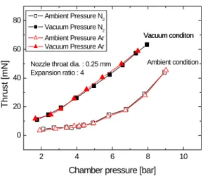
Fig. 6 Comparison of thrusts (Ambient vs. Vacuum)
2 4 6 8 10
0 20 40 60 80
Thrust [mN]
Chamber pressure [bar]
Calulated (Ambient pressure) Measured (Ambient pressure) Calulated (Vacuum) Measured (Vacuum)
Theoretical value Nozzle throat dia. : 0.25 mm Expansion ratio : 4 Propellant : Nitrogen
Fig. 7 Comparison of thrusts (Exp, CFD, Theory)
2 4 6 8 10
-30 0 30 60 90 120
Isp [s]
Chamber pressure [bar]
Calculated (Ambient pressure) Measured (Ambient pressure) Calculated (Vacuum) Measured (Vacuum)
Theoretical value
Nozzle throat dia. : 0.25 mm Expansion ration : 4 Propellant : Nitrogen
Fig. 8 Comparison of specific impulse (Exp, CFD, Theory)
Experiments are conducted in ambient and low- vacuum (100 Pa) conditions. Experimental results are compared with CFD analysis and theoretical value.
Figs. 6, 7, 8 show the performance results of circular micro nozzle in ambient and vacuum condition. In ambient condition, thrusts do not increase linearly in
low-Reynolds region. In vacuum condition thrusts increase linearly but specific thrust is a curved line. It is well known that exit pressure affects flow of subsonic boundary layer. In micro nozzle flow if ambient pressure is high enough to cause flow separation, micro nozzle results in poor thrust performance. Also viscosity affects efficiency of micro propulsion system. Consequently efficiency of micro nozzle will be decreased by pressure gradient and viscosity.
3. THERMAL TRANSPIRATION BASED ON PROPULSION SYSTEM
From the micro thrust experiments, we experience losses from minimization of propulsion system, especially thrust loss in low pressures under ambient condition. To overcome this loss, we need to study new conceptual propulsion system (Fig. 9).
Fig. 9 Requirement of new conceptual micro propulsion system
Using self-pumping by thermal transpiration in the free molecular regime may overcome the defect.
Temperature gradient in free molecular regime can pump propellant without moving part, lubricating oil, fluid. So it doesn’t have losses due to viscosity and will not need high-pressure tank of propellant theoretically. It need only device for temperature gradient. If thermal transpiration is applied to micro propulsion devices, we could decrease losses of conventional propulsion system.
Flow of gas is classified to continuous flow, transition flow, free molecular flow according to Knudsen number.
Kn = λ l
(2)
Reynolds (1879) is a first researcher who studied thermal transpiration using porous stucco plate [4].
Knudsen proved it experimentally. His study was
stopped because of poor fabrication technology at that
time. Recently Prof. Muntz in USC and Jet Propulsion
Lab. in NASA are studying thermal transpiration
actively [2].
The Principle of thermal transpiration (Knudsen pump) requires two chambers filled with gas and connected with membrane whose characteristic length is smaller than mean free path of the gas molecules (Kn>1). When one side chamber is heated, the resulting gas temperature gradient induces the difference of impingement rate of gas which has temperature variation. Then fluid moves from low temperature side to high temperature side.
3.1 Research issues
Knudsen pump’s efficiency is exponentially increased in free molecular regime. To meet this condition, we need nanoporous material (such as aerosel membrane) with low thermal conductivity because the larger temperature gradient induces larger pressure gradient and maximum flow (cold to hot).
But instead of using nanoporous aerogel membrane, we choose to use meso-scale level membrane in vacuum facility.
10-2 100 102 104 106
10-4 10-2 100 102 104
Knudsen number
Pressure [Pa]
Pressure vs. Kn Hole Dia. : 0.1 mm Tc : 288.15 K
Kn=1 at Pressure=70 Pa
Fig. 11 Pressure vs. Knudsen number
Figure 11 shows variation of Knudsen number according to the pressure in membrane with hole diameter of 0.1mm. Knudsen number is a main factor affecting flow characteristic that is most important in performance for application to propulsion system. We adopt back pressure of 70 Pa for simulation of free molecular regime where Knudsen number is more than 1. Because the larger Knudsen number becomes, the better flow characteristic becomes.
Temperature gradient is energy source of flow in thermal transpiration. Large temperature gradient
causes high pressure gradient. When pressure gradient is minimum and temperature is maximum, mass flow becomes maximum.
⎪⎭
⎪⎬
⎫
⎪⎩
⎪⎨
⎧
⎟⎟
⎠
⎞
⎜⎜
⎝
−⎛
⎟⎟
⎠
⎞
⎜⎜
⎝
⎟ ⎛
⎠
⎜ ⎞
⎝
= ⎛
c c h h
T P T P k m L
M
r2 / 3 1 .
3 8 π
(3)
300 375 450 525 600
1E-3 0.01 0.1 1 10 100
Hole Dia. : 0.1 mm Hole Dia. : 0.2 mm
Mass flow rate [g/min] x 100
Hot-section Temperature [oC]
- condition : Pressure : 70 Pa, Tc : 288.15oC
Hole Dia. : 1 mm
Hole Dia. : 0.5 mm
Fig. 12 Temperature vs. Mass flow rate according to hole diameter (air)
Figure 12 shows variation of mass flow rate induced by temperature gradient according to hole diameter. This is theoretical result and it is based on low vacuum condition of 70 Pa. Mass flow rate is increased according to hole diameter and temperature gradient. Fig. 13 shows estimated maximum mass flow rates for each hole diameter of membrane with hundred holes, 100 % efficiency and 300
oC temperature gradient.
0.0 0.2 0.4 0.6 0.8 1.0
0 10 20 30
Mass flow rate (g/min) x 100
Hole Diameter (mm) Hole Diameter vs.Mass flow meter - Condition -
Th : 573.15 K Tc : 288.15 K Ph = Pc
Fig. 13 Estimated maximum mass flow rate
As scale of membrane becomes larger, Knudsen number decreases and total efficiency of Knudsen pump decreases and total efficiency of Knudsen pump decreases.
Fig. 14 shows schematic of Knudsen pump composed of front section, membrane, connector section.
T1 < T2
P1 T1 P2 T2
Condition for max. efficiency
2 1 2 1
T T PP =
Fig. 10 Principle of Knudsen pump
Fig. 14 Schematic of Knudsen pump
Fig. 15 shows manufactured membrane. To characterize Knudsen pump, we select Polyimide that has low thermal conductivity (0.29 W/mK) and can stand high temperature (300
oC) for long time. And we fabricated membrane with hole diameter of 1, 0.5, 0.2, 0.1 mm using precision manufacturing.
Fig. 15 Manufactured membrane (Material : Polyimide)
Fig. 16 Variation of pressure gradient
Fig. 17 Variation of pressure efficiency
Figure 16 shows variation of pressure gradient according to hot-section temperature for 0.5 mm hole diameter, 2 mm thickness membrane. We compared
with characteristics of pressure variation according to Knudsen number. Although characteristic length is fixed to 0.5 mm, mean free path is changed by back pressure.
Figure 17 shows that pressure efficiency increases as Knudsen number increases.
Fig. 18 Research goal and research issues
Figure 18 shows our research issue and goal. We will study possibility of application to micro thrust system based on thermal transpiration.
4. Conclusion
In this study, we demonstrated that viscosity and back pressure cause flow losses in micro nozzle and decrease efficiency of micro propulsion system under ambient and vacuum conditions using experiment and CFD analysis. To overcome these losses, we suggest thermal transpiration based propulsion system.
Experimental results show that pressure gradient efficiency of Knudsen pump is increased to maximum 82% according to Knudsen number and thick membranes are more effective than thin membranes in transition flow regime.
ACKNOWLEDGMENTS
This work was supported by the Korea Research Foundation Grant funded by Korean Government (MOEHRD, Basic Research Promotion Fund) (KRF- 2006-311-D00043) and partially supported by grant No. KOSEF R01-2005-000-11735-0 from the basic research program of the Korea Science & Engineering Foundation.
References
1) Myongshin Han, Jihan Seo, Rhoshin Myong, Hwanil Huh, “Analysis of Flow Fields in a Small Scale Nozzle Using a Navier-Stokes CFD Modle," Proceedings of the 2004 KSAS Fall Conference, 2004, pp. 699-702.
2) G. Pham-Van-Diep, P. Keeley, P. Muntz, E. and P. Weaver, D. “A micromechanical Knudsen compressor," In Rarefied Gas Dynamics. eds. J.
Harvey, G. Lord, Oxford Univ. Press, 1999.
3) Ahsan R. Choudhuri, Benjamin Baird, S. R.
Gollahalli and Steven J. Schneider, “Effects of Geometry and Ambient pressure on Micro-nozzle Flow," AIAA Paper 2001-3331, 2001.
4) M. Knudsen, “Eine Revision der Gleichgewi chtsbedingung der Gase. Thermische Molecula rstr'omung," Ann Phys. Leipzig, Vol. 31, 1910, pp. 205-229.
Membrane
Connector section Heating & Thermocouple
Valve Front section
Differential Pressure