• 검색 결과가 없습니다.

Fuzzy Logic Based Energy Management For Wind Turbine, Photo Voltaic And Diesel Hybrid System

N/A
N/A
Protected

Academic year: 2021

Share "Fuzzy Logic Based Energy Management For Wind Turbine, Photo Voltaic And Diesel Hybrid System"

Copied!
10
0
0

로드 중.... (전체 텍스트 보기)

전체 글

(1)

1. Introduction

Electricity is the most basic need of routine life in this modern era. However, it is quite difficult to connect remote areas with the grid system such as hilly areas and villages located far away from urban territories. Electrification by grid extension requires a huge investment, which is not feasible in most cases. These facts make the electrification more catastrophic in rural areas [1, 2]. These remote areas are widely covered by standalone diesel generators. However, these fossil fuel energy sources have high operating and maintenance cost which ends up at very expensive electricity production and beyond reach of common people. Fortunately, most of the remote areas reside among the high wind region or have abundant solar potential which are enough to develop wind or solar energy power generation systems [3, 4].

On the other hand, even though urban areas are getting power directly from main grid, mostly the back end energy production sources are fossil fuels such as diesel, gas or residual oil. As it is well understood that these fossil fuels are not going to last forever, high demand and increase in daily consumption will soon boost its cost and we may run out of these resources in near future [5].

Therefore, we need to divert our attention towards renewable or green energy sources. These energy sources include wind turbines, photo voltaic systems, biomass, terrestrial heat, hydro turbines etc.

are environment friendly with everlasting production resources. Various engineers and researchers find out great ideas on how these renewable energy sources can be utilized to provide maximum outcome. Connecting them in different ways with energy storage and other backup systems for continuous energy supply has provided many options. Hybrid systems are getting popular because of its reliable and uncut energy supply even in worst environmental conditions. Hybridization of

Fuzzy Logic Based Energy Management For Wind Turbine, Photo Voltaic And Diesel Hybrid System

Muhammad Talha*, Furqan Asghar*, and Sung Ho Kim**

*School of Electronics and Information Engineering, Kunsan National University

**School of IT, Information and Control Engineering, Kunsan National University

Abstract

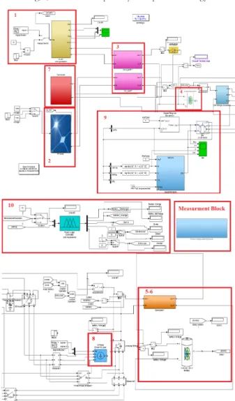
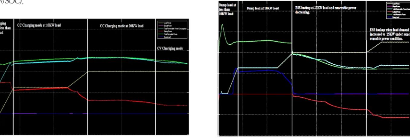
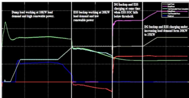
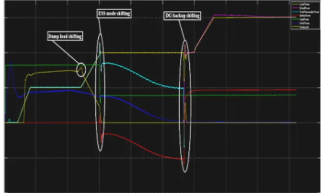
Rapid population growth with high living standards and high electronics use for personal comfort has raised the electricity demand exponentially. To fulfill this elevated demand, conventional energy sources are shifting towards low production cost and long term usable alternative energy sources. Hybrid renewable energy systems (HRES) are becoming popular as stand-alone power systems for providing electricity in remote areas due to advancement in renewable energy technologies and subsequent rise in prices of petroleum products. Wind and solar power are considered feasible replacement to fossil fuels as the prediction of the fuel shortage in the near future, forced all operators involved in energy production to explore this new and clean source of power. Presented paper proposes fuzzy logic based Energy Management System (EMS) for Wind Turbine (WT), Photo Voltaic (PV) and Diesel Generator (DG) hybrid micro-grid configuration. Battery backup system is introduced for worst environmental conditions or high load demands. Dump load along with dump load controller is implemented for over voltage and over speed protection. Fuzzy logic based supervisory control system performs the power flow control between different scenarios such as battery charging, battery backup, dump load activation and DG backup in most intellectual way.

Key Words : Fuzzy Logic, Energy Management System (EMS), Energy Storage System (ESS), Wind Turbine and Photo Voltaic Hybrid System, Diesel Generator Backup and ESS Charging, Dump Load

This is an Open-Access article distributed under the terms of the Creative Commons Attribution Non-Commercial License (http://

creativecommons.org/licenses/by-nc/3.0) which permits unrestricted non-commercial use, distribution, and reproduction in any medium, provided the original work is properly cited.

This work was supported by Business for Academic-Industrial Cooperative establishments funded Korea Small and Medium Business Administration in 2015 (No.

C0268141)

JKIIS

http://dx.doi.org/10.5391/JKIIS.2016.26.5.351

Received: Sep. 26, 2016 Revised : Oct. 18, 2016 Accepted: Oct. 20, 2016

Corresponding authors

[email protected]

(2)

green energy sources with some standalone backup system such as diesel generator, outcomes a sustainable and durable hybrid system.

Now a days, most of the installed hybrid systems rely primarily on non-renewable resources, with renewable energy sources providing supply in case of low demand and charging the batteries simultaneously [6].

Wind diesel hybrid, PV diesel hybrid and wind PV diesel hybrid systems are some well-known topologies. A centralized control system is required to maintain the balance between supply and load demand. This paper is about centralized control of wind turbine, photovoltaic and diesel hybrid system. Wind turbine and photovoltaic systems are most effective renewable energy sources.

It is evident that combining both of them in a single system will boost up their effectiveness, diesel generator is added as a backup in emergency situations.

In this proposed hybrid topology, renewable energy sources are considered as primary source and diesel generator is acting as secondary backup source for emergency situations. A fuzzy logic based centralized control is designed for the balancing and control of production and load side. Energy storage backup system, dump load, load management, diesel backup and charging system are the key features of this proposed methodology. Fig.1 briefly explains the whole scheme of designed system. This control system continuously monitor extra power and state of energy storage system.

Furthermore, maximum power point tracking (MPPT) algorithms for wind turbine and photo voltaic system has been implemented to ensure its high adaptability. Super capacitors are implemented as DC- Link to consume high current fluctuation during MPPT process. DC- Link is connected to Inverter, ESS charging and discharging control system and dump load at the same time. FUZZY logic controller

monitors extra power, state of charge (SOC) level and take decisions accordingly. In normal condition when renewable energy sources are able to provide enough power to hold the load demand, then ESS batteries will be charged with surplus power. If the batteries are Fig. 1. Proposed System Block Diagram

Fig. 2. Flow Chart of Proposed System Operational Strategy

Fig. 3. Matlab/Simulink based Complete Proposed System Operational Strategy

(3)

fully charged, then dump load will consume that excessive power.

Second case is when load demand is higher than renewable source power, energy storage system will provide the remaining power and fuzzy logic will control the power to be provided to load according to extra power (deficit power) calculation. ESS will keep on giving back up until its SOC drops below minimum threshold level. At this point, if renewable energy is still below the load demand, then load will be disconnected from renewable energy sources and diesel generator (DG) will turn on. In this case, DG is responsible of providing backup power and also charging ESS. Load and ESS charging process will be shifted to renewable energy sources when they can provide sufficient power to hold the load demand.

2. Wind/PV/DG Hybrid Energy Storage and Energy Management System

This hybrid Wind/PV/DG hybrid system deals with energy storage, backup and energy management system. A systematic approach is carried out to make the system economical and better than conventional hybrid systems. Fuzzy logic based intelligent centralized control system makes this proposed system highly effective for various scenarios. Matlab/Simulink programming environment is used for implementation of this proposed system.

Complete system is shown in Fig.3. It consists of the following parts explained in detail and indicated in Fig.3 respectively.

2.1. Wind turbine

Wind energy conversion systems known as wind turbines are designed to convert wind kinetic energy into mechanical power. This mechanical power can be used to drive different kind of machines such as pumping water, mill grains or drive machinery. Electric generators are usually used to transform this mechanical power into electrical energy. Generated electricity can be either stored in batteries, or used directly. Main parts of a physical wind turbine are blades, rotor, generator, direction system, protection system and tower [7]. In Matlab/Simulink programming environment, wind turbine is implemented using it physical equations and dynamic features to get accurate response like a practical system.

2.2. Photo Voltaic (PV) system

PV systems are used to convert sunlight into electricity with non

inverting heat engine. PV devices are solid state; therefore, they are rugged and simple in design. PV systems are reliable, emission-less and minimum maintenance requirements to operate [8].

PV array system is implemented in Matlab/ Simulink environment in most accurate way to ensure its maximum efficiency. 15KW PV model is designed and implemented in Matlab/Simulink for this experiment.

2.3. Maximum power point tracking (MPPT)

MPPT is an electronic system which operates wind turbine or PV module in a manner that allows them to produce the maximum power they are capable of over certain environment condition. It is not a mechanical tracking system that physically moves the module, but a fully electronic and automatic process which varies the electrical operating points. There are several MPPT techniques with various benefits and drawbacks such as incremental conductance (IC), perturb and observe (PO), current control or torque control etc.

Torque control or current control technique is used because of its effectiveness and accuracy over other methods. This technique uses reference current value with respect to output voltages of the system[9-10]. Output voltage of wind turbine or PV module directly depends on wind speed and solar irradiance respectively. Equation for the reference current can be obtained from the characteristics curves of wind turbine generator and PV module shown in Fig.4.

It is quite easy to derive mathematical equations of this curve using curve fitting tool (CFtool) in Matlab. Resulting equations are used to calculate the reference current against each voltage point and further used in PID controller as reference value which finally controls the current autonomously after perfect gain tuning.

Fig. 4. Wind Turbine and PV module reference current curves

(4)

2.4. Super capacitors (SC) as DC link

Super capacitor, also known as ultra-capacitor or double-layer capacitor differs from a regular capacitor because it has very high capacitance. A capacitor stores energy by means of a static charge as opposed to an electrochemical reaction. Creating voltage differential on the positive and negative plates charges the capacitor.

There are three types of capacitors and the most basic is the electrostatic capacitor with a dry separator. This classic capacitor has very low capacitance and is mainly used to tune radio frequencies and filtering. The size ranges from a few pico-farads (pf) to low microfarad (μF).

The electrolytic capacitor provides higher capacitance than the electrostatic capacitor and is rated in microfarads (μF), which is a million times larger than a pico-farad. These capacitors deploy a moist separator and are used for filtering, buffering and signal coupling. Similar to a battery, the electrostatic capacity has a positive and negative that must be observed.

The third type is the supercapacitor, rated in farads, which is thousands of times higher than the electrolytic capacitor.

Supercapacitor is used for energy storage undergoing frequent charge and discharge cycles at high current and short duration.

These capacitors when used as dc link provides a perfect source to consume big current spikes and sustainable source for smooth energy flow. In case of renewable energy sources, MPPT is compulsory to be executed to get maximum possible power from system. MPPT generates high current fluctuations under varying environmental conditions. Super capacitor is implemented as dc link for three phase inverter in this project to get best possible performance from designed system [11].

2.5. Bidirectional BUCK-BOOST converter

Bidirectional dc-dc converter along with energy storage has become a promising option for many power related systems including hybrid vehicle, fuel cell vehicle, renewable energy system, etc. this use of converter not only reduce the cost and improve efficiency, but also boost the system performance. In renewable energy applications, multi input bidirectional dc-dc converter can be used to combine different types of energy sources. This multi-input bidirectional dc-dc converter is the core that interconnects power sources with storage elements and maintain smooth power flow in system. Recently, clean energy resources such as photovoltaic arrays and wind turbines have been exploited for developing renewable

electric power generation systems. Bidirectional dc-dc converter is often used to transfer the solar energy to capacitive energy source during the sunny time, whereas it delivers energy to the load when dc bus voltage is low. This converter is regulated by the solar array photovoltaic level to maintain stable load bus voltage for efficient usage of solar array and storage battery. Based on the placement of the auxiliary energy storage, this bidirectional dc-dc converter can be categorized into buck and boost type. The buck type is to store energy placed on the high voltage side and boost type is to have it placed on the low voltage side.

To realize the double sided power flow in bidirectional dc-dc converters, the switch cell should carry the current on both directions.

Fig. 5. Bidirectional BUCK-BOOST converter block diagram

It is usually implemented with a unidirectional semiconductor power switch such as power MOSFET (Metal-Oxide-Semiconductor- Field-Effect-Transistor) or IGBT (Insulated Gate Bipolar Transistor) in parallel with a diode because the double sided current flow power switch is not available. For the buck and boost dc-dc type converters, bidirectional power flow is realized by replacing the switch and diode with double sided current switch cell shown in Fig.5. This bidirectional Buck-Boost converter is implemented for charging and discharging of ESS.

2.6. Battery charging and backup controller

Battery charging and backup controller consists of separate

bidirectional buck-boost dc-dc converters controlled by PID

controllers. Buck converter is used to charge battery bank in constant

current-constant voltage (CC-CV) mode. Charging voltages are used

as input to buck converter from dc link. Buck converter controls

the charging current in CC mode and maintains constant charging

voltage in CV mode . S-function builder is used to implement

charging process in C code. Boost converter is responsible for battery

backup process. Whenever battery backup process is initiated, boost

converter will be automatically activated by fuzzy logic based central

(5)

control system. It will set the required discharging power level using PID controllers. PID controllers are used for controlling the charging and discharging power of ESS.

2.7. Dump load controller

Dump load along with its controller is responsible to consume extra power when ESS is fully charged and renewable energy sources are producing higher amount of power than the load demand.

Dump load consumes extra power to maintain the sustained output at inverter side. Dump load controller is a buck converter with PID controller. Power consumption command will be set by fuzzy logic controller. Dump load can be a water heating system, room heater or some other positive way.

2.8. Three-phase inverter and dynamic load

Sinusoidal pulse width modulation (SPWM) three phase inverter is used for DC-AC conversion in this system. Dynamic load is responsible for varying the load demand with respect to time, which enables the system to ensure its reliability in varying load conditions.

2.9. Diesel generator

Generators are useful appliances that supply electrical power during power outage and prevent discontinuity of daily activities or disruption of business operations. Generators are available in different electrical and physical configurations for different applications. In the following sections, we will have a look on generator functions, the main components of a generator and how a generator operates as a secondary source of electrical power in residential and industrial applications.

An electric generator is a system that converts mechanical energy obtained from an external source into electrical energy as the output.

It is important to understand that a generator does not actually ‘create’

electrical energy. Instead, it uses supplied mechanical energy to force the movement of electric charges present in the wire of its windings through an external electric circuit. This flow of electric charge constitutes the output electric current supplied by the generator. This mechanism can be understood by considering the generator to be analogous to a water pump, which causes the flow of water but does not actually ‘create’ the water flowing through it.

Modern day generator works on the principle of electromagnetic induction discovered by Michael Faraday in 1831-32. Faraday discovered that the flow of electric charges can be induced by moving

an electric conductor such as a wire that contains electric charge in a magnetic field. This movement creates a voltage difference between the two ends of wire or electric conductor, which in turn causes the electric charges to flow to generate electric current. Matlab/Simulink environment provides suitable electrical and mechanical models. A diesel generator with mechanical model of diesel engine is designed and coupled with a synchronous machine. Diesel engine model is shown in Fig.6

Fig. 6. Diesel Engine model

2.10. Fuzzy logic based energy management system

Fuzzy logic systems (FLS) produce acceptable but definite output in response to incomplete, ambiguous, distorted, or inaccurate (fuzzy) input. Fuzzy logic (FL) is a method of reasoning that resembles human reasoning. The approach of FL imitates the way of decision making in humans that involves all intermediate possibilities between digital values 0 and 1.

It can be implemented in systems with various sizes and capabilities ranging from small micro-controllers to large networks, workstation based control systems, in hardware, software or a combination of both. Fuzzy logic is useful for commercial and practical purposes.

2.10.1. Fuzzy logic architecture

Fuzzification module transforms system inputs such as crisp numbers into fuzzy sets. Knowledge base stores IF-THEN rules provided by experts. Inference Engine simulates the human reasoning process by making fuzzy inference on the inputs and

Fig. 7. Fuzzy logic block diagram

(6)

IF-THEN rules. Defuzzification Module transforms the fuzzy set obtained by the inference engine into a crisp value.

2.10.2. Membership Function

Membership functions allow us to quantify a linguistic term and represent fuzzy sets graphically. A membership function for a fuzzy set A on the universe of discourse X is defined as μA:X → [0,1].

Here, each element of X is mapped to a value between 0 and 1.

It is called membership value or degree of membership. It quantifies the degree of membership of the element in X to the fuzzy set A.

There can be multiple membership functions applicable to fuzzify a numerical value. Simple membership functions are used only, as complex functions does not add more precision in the output.

Fuzzy logic provides a smooth way of getting several output cases according to input conditions. Proposed fuzzy logic control system is designed to provide better and polished outputs as compared to previous hard switching techniques. Hard limiter switching techniques just ensure the turning on and off, rest of calculation must be done separately. Hard limiting cause disturbance in the system while shifting states. This proposed fuzzy system has two inputs, five outputs and twenty one rules to provide all possible input and output combinations according to designed system. Membership functions are designed to provide the stabilized output for system efficient performance.

Fig. 8. Input membership function

To design fuzzy logic input or output, a proper membership function type must be selected. The percentage overlap between each membership function should be carefully chosen to ensure response. Input and output membership functions are shown in figures. Input membership functions are extra power and battery

state of charge (SOC). Extra power input consist of negative and positive power in Kilowatts (KW) in which negative extra power identifies the power deficit and positive extra power indicates the surplus power. SOC indicates the ESS state such as empty, medium or full. Output membership functions are weighted according to the deficit and surplus power levels and SOC. Designed rule base controls energy flow in system. Input membership functions are show in Fig.8.

Output membership functions consists of battery discharging power, battery charging power, dump load power, diesel switch and load switch. Battery discharging power indicates the power level decided by deficit power and SOC. Battery charging and dump load power level are calculated by surplus power and SOC. If SOC is empty or medium, then battery will be charged using surplus power. Otherwise surplus power will be consumed by dump load.

Diesel and Load outputs are just switching outputs. Load output will stay on and diesel will stay off in normal conditions when SOC is enough for backup or surplus energy is available. Load is off and diesel is on when SOC drops below minimum level and extra power is in deficit. In diesel generator backup case, diesel generator is responsible to provide required power to load and charge the ESS

Fig. 9. Output membership function

(7)

simultaneously. Fig.9 shows all output membership functions.

3. Simulation Experiment and Results

Matlab/Simulink programming environment is used to simulate and test the proposed algorithm. Matlab/Simulink is a graphic based programming environment which allow us to make any type of electrical, mechanical, graphical or electromechanical system and its control. Matlab/Simulink is a great tool to design, test and verify any control system. Carefully designed fuzzy rule base is used to ensure highest possible efficiency of proposed system. Designed fuzzy rules are show in Table.1.

3.1. ESS CC-CV charging mode

Battery charging mode is also the normal mode of operation for our designed system. Here, wind turbine and PV modules generates power more than the load demand. Extra power is used to charge the ESS. Constant current and constant voltage (CC-CV) charging system is included for safe charging process and to prevent the ESS from over voltage and overheating. Basically CC-CV is a common charging process used for high voltage battery systems where serially connected cells are higher in number. Initially ESS has low SOC, charging is started in constant current mode by supplying possible maximum current to the batteries. This phenomenon boosts the charging process at the start. When battery voltage reaches the gassing voltage level, system is shifted from constant current mode to constant voltage mode. Constant voltage same as gassing voltage value is applied to carry out remaining charging process. Charging current decreases in this mode as SOC increases and at the end it drops to approximately zero when SOC reaches it maximum value (100% SOC).

Table 1. FUZZY rules base

Fig.10 explains the ESS charging process under varying load conditions. Surplus power decreases when load demand increases.

That’s why, ESS charging power in CC mode will decrease accordingly. Fig.11 shows the ESS charging power in (red line) and load demand (yellow line). System response in ESS charging mode is shown in different scenarios such as less than 10KW load demand, 10KW load demand and 20KW load demand to check the performance under varying load cases. Also we can see that ESS charging shifts to CV mode to complete charging process. Dump load will automatically turn on to consume extra power if battery is fully charged or in case of any surplus power during charging process.

Fig. 10. System Output Characteristics in ESS Charging Mode Fig. 11. System Output Characteristics in Dump Load and ESS backup Mode

(8)

3.2. Dump load mode

Dump load mode is activated when ESS is fully charged and renewable energy sources keep generating extra power which needs to be consumed to keep the dc link voltage at constant level.

Dump load controller is simple dc load controlled via PID controller.

PID controller reference power is given by fuzzy logic control system calculated from extra generated power and load. Dump load can be used as water heating system, room heating system or some other sources as mentioned earlier. Fig.11 shows dump load operation under varying load cases. Dump load will turn on if there is surplus power available and ESS is fully charged. It can be seen in figure that dump load power consumption (blue line) increases when there is surplus power. As load demand increases in later part, dump load power decreases due to decrement in surplus power. Moreover, dump load power consumption reaches to zero when there is no surplus power or there is a deficit power.

3.3. ESS backup mode

ESS backup deals with deficit power issues in power system.

If generated renewable power in not enough to hold the load demand, ESS is responsible to fulfill the power deficiency. During bad environment or in high load demand cases, renewable power sources are not able to sustain the load fully. ESS provides the remaining power required to meet load demand. Fig.11 shows the ESS backup system under low renewable power state and also for increasing load demand case. Initially, load demand is 20KW whereas renewable power generation drops below 20KW. As this happens, ESS backup mode is activated by fuzzy rule base and deficit power is calculated. Power command is send to ESS charging and discharging controller, which controls the bidirectional buck- boost converter to provide that specific amount of power. As it can be seen in later part of power graph, ESS backup power increases with rise in load demand. Load demand increases from 20KW to 25KW. Likewise ESS backup power boosts up to reach the demand to maintain system stability.

3.4. DG backup and ESS charging mode

DG backup and ESS charging mode is last mode of operation.

DG backup system is used in worst scenarios, where renewable power sources are not able to provide enough power and ESS is also running short of power storage. When SOC drops below the threshold value, fuzzy logic control system sense this critical situation

and immediately turns on the DG backup system and connect it to load. Load will be cutoff from renewable sources at same time. DG backup system is responsible for two things, first one is to provide the power to load for uncut and smooth electrification and second one is to charge ESS. DG’s should be operated at its peak power rating to get maximum efficiency with respect to fuel consumption.

For this, ESS charging is also conducted in DG backup case.

Fig. 12. System Output Characteristics in DG Backup and ESS Charging

Fig.12 shows various working conditions of system and smooth shifting response from one case to another. First condition in this figure is dump load mode which is turned on because of surplus power. Second condition is shifting from dump load case to ESS backup. Then ESS starts giving backup as renewable power generation drops below the load demand.

Third condition is DG backup and ESS charging. In this scenario, ESS power runs down and system is unable to meet load demand.

Fuzzy logic system analyze this situation and takes decision in response to sustain the load. For this, DG is turned on and connected to load as well as with ESS charging system. Load will stay cutoff from renewable sources until ESS charged to 100%. In this case, DG will be turned off and ESS mode will be activated again.

4. Comparison between FUZZY logic control system and Hard limiting controllers

In previous energy management system, hard limiting logic

was implemented for load shifting or ESS charging and discharging

processes. In this section, comparison between previous hard

limiting logics and proposed fuzzy logic system is presented. Same

system consisting of hard limiting logic control using state machine

is designed to study its performance. Hard limiting logic provides

simple switching mechanism for shifting between various scenarios

(9)

which creates high disturbance and voltage spikes. Fig.13 shows the power spikes in hard limiting logic while shifting the system between various modes. These spikes may cause high current flow through switches or damage to electrical instruments. Even though, various methods can be used to smooth this response such as some well known controllers and filters, but this might increase the computation time, make system bulky and increase response time.

Slower response indirectly refers to low efficiency of system

5. Conclusion

This proposed work consists of hybrid energy management system using wind turbine, PV module, Diesel generator along with energy storage and backup system (ESS). Reference current based MPPT technique is implemented to provide absolute maximum power point value at varying environmental conditions which increases effectiveness of used renewable energy sources (wind turbine, PV). Super capacitor is used as dc link to consume high current fluctuations and giving smooth response at output during MPPT implementation.

Moreover, CC-CV based ESS charging process improves the battery life and provides overvoltage and over heating protection.

Fuzzy logic control system results has proved its supremacy over hard limiting systems such as conditions switching logics and state machine. Dump load is introduced for stable power flow and to avoid over voltage on dc link in low load demand case. Fuzzy logic based centralized control system controls the power flow in smooth and efficient way. Results proved that proposed controller prevents the system from energy loss, provides protections from electricity failure in all possible kind of scenarios such as environmental issues

or load demand issues and offers very smooth transitions between all states.

References

[1] Gabin Koucoi, Daniel Yamegueu, Quac-Tuan Tran, Yezouma Couliblay, Herve Buttin, “Energy Management Strategies for Hybrid PV/Diesel Energy Systems: Simulation and Experimental Validation ” International Journal of energy and Power Engineering, vol. 5, no, 1, pp. 6-14, 01 May 2016.

[2] U. Suresh Kumar and P. S. Manoharan, “Economic analysis of hybrid power systems (PV/diesel) in different climatic zones of Tamil Nadu, ” Energy Convers. Manag., vol. 80, pp. 469-476, 2014.

[3] D. Tsuanyo, Y. Azoumah, D. Aussel, and P. Neveu, “Modeling and optimization of batteryless hybrid PV (photovoltaic)/

Diesel systems for off-grid applications, ” Energy, pp. 1-12, 2015.

[4] D. Yamegueu, Y. Azoumah, X. Py, and N. Zongo,

“Experimental study of electricity generation by Solar PV/diesel hybrid systems without battery storage for off-grid areas, ” Renew. Energy, vol. 36, pp. 1780-1787, 2011.

[5] S.Rehman and I.El-Amin “Study of a solar pv/wind/diesel hybrid power system for a remotely located population near Arar, Saudi Arabia ” Energy Exploration and Exploitation vol.

33, no. 4, pp, 519-620, 2015.

[6] B.Wichert and WB. Lawrance “Application of Intelligent Control Methods to the Management of Modular Hybrid Energy Systems ” Proceedings of solar ’97 Australian and New Zealand Solar Energy Society.

[7] AIMU Technical service committee, “Wind Turbine Paper”

January 2012.

[8] GeorgetaVidican, Wei Lee Woon, Stuart Madnick, “Measuring Innovation Using Bibliometric Techniques-The Case of Solar Photovoltaic Industry ” ,(2009).

[9] Muhammd Talha, Sung Ho Kim, “Comparative study on the performance of various wind turbine MPPT algorithms ” journal of robotics and systems in jeju, jeonbuk branch conference. pp 96-99 12, 2014.

[10] Furqan Asghar, Sung Ho Kim, “Comparative study on the performance of various MPPT algorithms for solar photovoltaic

Fig. 13. Output Characteristics of Hard Limiting Logic based Energy Management

System

(10)

system ” journal of robotics and systems in jeju, jeonbuk branch conference. pp 91-95 12,2014.

[11] Tihomir Cihak, Zeljko Jakopovic “Supercapacitors in power converter DC link ” 2015

[12] M. C. Knauff, C. J. Dafis, D. Niebur.. “Simulink Model for Hybrid Power System Test-bed ”, Electric Ship Technologies Symposium, pp., 421 - 427, 2007.

[13] Saleh Elkelani Babaa, Matthew Armstrong, Volker Pickert,

“Overview of Maximum Power Point Tracking Control Methods for PV Systems, ” Journal of Power and Energy Engineering, vol 2, pp. 59-72, August, 2014.

[14] Wei Chen, Hui Shen, Bifen Shu, Hong Qin, Tao Deng,

“Evaluation of performance of MPPT devices in PV systems with storage batteries, ” Renewable Energy vol 32, pp. 1611- 1622, 2007.

[15] S. Arnaltes, “Comparison of Variable Speed Wind Turbine Control Strategies, ” Proceedings of the International Conference on Renewable Energies and Power Quality, pp.

1-6, 2003.

[16] Saravana, S. D, “Modeling and Simulation of Incremental Conductance MPPT Algorithm for Photovoltaic Applications, ” International Journal of Scientific Engineering and Technology, ISSN: 2277-1581, vol. 2, issue no. 7, pp. 681-685, 2013.

[17] Parash Acharya, Small Scale Maximum Power Point Tracking Power Converter for Developing Country Application, University of Canterbury. Electrical and Computer Engineering, 2013.

저 자 소 개

Muhammad Talha

2012 : received the B.S. degree in Electrical Engineering from The University of Faisalabad

2015 : Control System Engineering from Kunsan National University

2015 ~ Now : Current Ph.D. student in Kunsan National University

Research : Energy System, Power converters, Embedded Systems, Sensor Networks

Phone : +82-10-3671-9667 E-mail : [email protected]

Furqan Asghar

2012 : received the B.S. degree in Electrical Engineering from The University of Faisalabad

2015 : Control System Engineering from Kunsan National University

2015 ~ Now : Current Ph.D. student in Kunsan National University

Research : Renewable Energy System, Artificial Neural Network, Fuzzy Logic

Phone : +82-10-2827-3513 E-mail : [email protected]

Sung Ho Kim

1984 : Electrical Engineering from Korea University

1986 : M.S from Korea University 1991 : Ph.D. from Korea University

1996 : JAPAN HIROSHIMA University POST- DOC

1991 ~ Now : professor at Kunsan National University

Research : Fuzzy Logic, Sensor Networks, Neural Network, Intelligent Control System

Phone : +82-10-2610-1224

E-mail : [email protected]

수치

Fig. 3. Matlab/Simulink based Complete Proposed System Operational Strategy
Fig. 4. Wind Turbine and PV module reference current curves
Fig. 5. Bidirectional BUCK-BOOST converter block diagram
Fig. 7. Fuzzy logic block diagram
+5

참조

관련 문서