Online ISSN: 2288-7253 DOI: https://doi.org/10.14579/MEMBRANE_JOURNAL.2020.30.4.213
1. Introduction
1)An alternative system to produce renewable energy is in large demand due to depleted levels of unrenewable
natural energy and increased usage of energy worldwide.
Polymer electrolyte membrane fuel cells (PEMFCs) is a key field within fuel cells which use a proton ex- change membrane to transport ions (H
+and OH
-). The key PEMFCs that will be focused on in this review
†Corresponding author(e-mail: [email protected], https://orcid.org/0000-0002-3820-141X)
미생물 연료 전지 적용을 위한 양성자 교환막에 대한 검토
김 지 민*
⋅라즈쿠마 파텔
**,†*연세대학교 융합과학공학부 바이오융합과, **연세대학교 융합과학공학부 에너지환경융합과
(2020년 7월 5일 접수, 2020년 7월 16일 수정, 2020년 7월 17일 채택)
Review on Proton Exchange Membranes for Microbial Fuel Cell Application
Ji Min Kim* and Rajkumar Patel**,†
*Bio-Convergence, Integrated Science and Engineering Division (ISED), Underwood International College, Yonsei University, 85 Songdogwahak-ro, Yeonsu-gu, Incheon 21983, South Korea
**Energy and Environmental Science and Engineering (EESE), Integrated Science and Engineering Division (ISED), Underwood International College, Yonsei University, 85 Songdogwahak-ro, Yeonsu-gu, Incheon 21983, South Korea
(Received July 5, 2020, Revised July 16, 2020, Accepted July 17, 2020)
요 약: 재생 불가능한 에너지 자원이 수년에 걸쳐 고갈됨에 따라, 재생 에너지 생산을 위한 보다 효과적인 방법에 대한 연구가 증가되었다. 연로전지 개발의 한 분야인 미생물 연료전지(MFC)는 이중 성능의 잠재력 덕분에 발전하였다. MFC는 박 테리아와 같은 전극 감소 생물에서 전력을 모아서 전기 에너지를 생산한다. MFC는 폐수를 연료로 사용하여 에너지를 생산하 고 폐수를 정화한다. 양성자 교환막(PEM)은 양극과 음극 챔버의 분리막으로, 양성자만 효과적으로 통과할 수 있게 하는 중요 한 역할을 한다. Nafion은 MFC에 상업적으로 사용되는 PEM이지만 비용, 생산 시간, 양성자 전도성 차원에서 보완할 점들이 많다. 본 리뷰 논문에는 Nafion을 대체할 수 있는 새로 개발된 PEM 몇 가지를 논의하였다. 또한, PEM, 혼합 PEM 및 복합 PEM에 기반한 MFC를 요약하고자 한다.
Abstract: As unrenewable energy resources have depleted over the years, the demand for renewable energy has increased promoting research for more effective methods to produce renewable energy. The field of fuel cell development, specifically microbial fuel cells (MFCs), has developed because of the dual performance potential of the technology. MFCs convert power by facilitating electrode-reducing organisms such as bacteria (microbes) as a catalyst to produce electrical energy.
MFCs use domestic and industrial wastewater as fuel to initiate the process, purifying the wastewater as a result. Proton exchange membranes (PEM) play a crucial role in MFCs as a separator between the anodes and cathodes chambers allowing only protons to effectively pass through. Nafion is the commercially used PEM for MFCs, but there are many setbacks:
such as cost, production time, and less effective proton conductivity properties. In this review there will be largely two parts. Firstly, several newly developed PEM are discussed as possible replacements of Nafion. Secondly, MFC based on PEM, blended PEM and composite PEM are summarized.
Keywords:
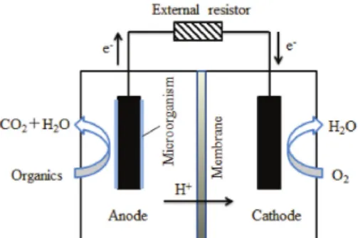
microbial fuel cell, graphene oxide, proton exchange membrane, membraneFig. 1. Schematic diagram of microbial fuel cell.
paper are microbial fuel cells (MFCs) which use in- dustrial/domestic wastewater to harvest energy and con- vert into electricity[1-14]. It can convert energy stored within the microbes (microorganisms) of the waste- water to electrical energy. Not only does MFCs gen- erate electricity, but also purifies the domestic/in- dustrial wastewater that produce fresh water for further use. Advanced research of optimizing MFC perform- ance will result into many benefits such as energy gen- eration, environmental safety, and freshwater production.
Schematic representation of MFC is presented in Fig.
1. The most crucial factor of the MFC that effects the overall performance is the proton exchange membrane placed in the middle of the two chambers (anode and cathode). It allows the H
+to effectively pass through from the anode chamber to the cathode chamber.
Additionally, it avoids short circuiting between the elec- trons and protons and maintain anaerobic conditions in the anode chamber.
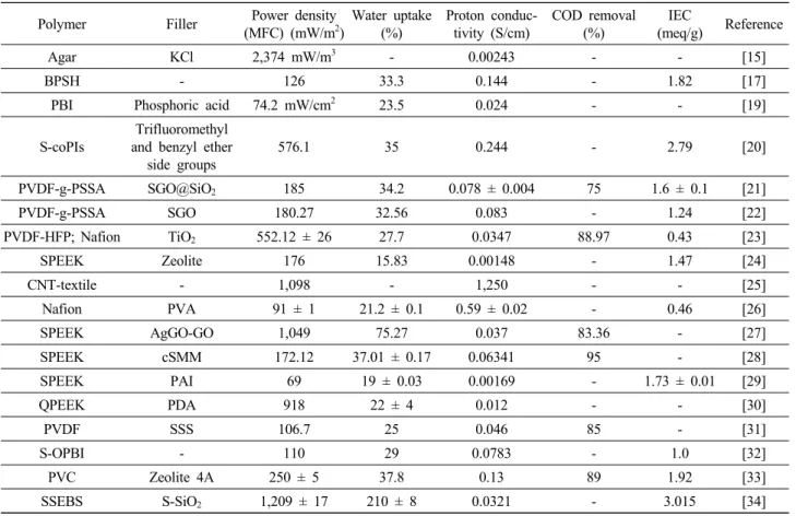
The most used proton exchange membrane (PEM) is the Nafion-117. Although Nafion is used the most, there are several setbacks to it including high cost of manufacture, unsatisfactory proton conductivity levels, and a long and complex manufacturing process. To im- prove MFC performance, extensive research is con- ducted to produce a superior alternative to the Nafion-117 with improved proton conductivity and an- ti-fouling properties. Performance of the different mem- branes in MFC is presented in Table 1. To characterize the synthesized membranes, the main imaging methods used were scanning electron microscopy (SEM), water uptake, proton conductivity, and transmission electron
microscopy (TEM). Many of the membranes synthe- sized goes through multiple steps that need to be re- checked to make sure that the reactions occurred effec- tively on the membranes. All the membranes introduced further are also tested by performance in either a two-chambered or single-chambered MFC over a des- ignated time period. The data is compared to the per- formance of Nafion-117 and if it performed better, it was thought to be a potential replacement for it. In this review microbial fuel cell primarily based on com- posite and blended proton exchange membrane are discussed.
2. Microbial Fuel Cell
Hernandez-Florez et al. reported synthesis of agar membranes by mixing different weights of agar from red algae as a polymer and distilled water as a sol- vent[15]. Once mixed, it was poured in Petri dishes and dehydrated into dry membranes. Agar-KCl mem- branes were synthesized in a similar fashion but mixed with corresponding amounts of KCl salt and agar poly- mer into distilled water. Three sets of membranes were synthesized which are: different percentages of only agar polymer (2, 4, 6, 8%), different percentages of agar polymer (2, 4, 6, 8%) and same percentage of KCl salt (10%), same percentage of agar (2%) with different percentages of KCl salt (2, 4, 6, 8, 10%).
The surface morphology of the synthesized membranes was analyzed using scanning electron microscopy.
Mechanical properties such as tensile strength and
maximum strain were tested as well as resistance and
proton conductivity. SEM images revealed a superficial
morphology of the composite membranes without po-
rosity and the KCl salts as “dots” on the surface. The
more KCl salt incorporated into the membranes, the
weaker and more brittle it was while an increase of
agar concentration with same concentration of KCl salt
showed an increase in strength. Proton conductivity of
membranes containing only agar polymer did not in-
crease much as the concentration increased. But the
conductivity of agar-KCl membranes increased drasti-
cally as agar component increased and KCl component stayed the same at 10%. MFC incorporated with the synthesized membranes were tested in single-chambers with Nafion-117 as the control. The dry membranes were coated with a catalyst before use and the electro- chemical characteristics were analyzed. SR-I was used as the biocatalyst over a short time interval. A trend showed which was that the increase of agar concen- tration resulted in better SC-MFC performance. When analyzed for a longer period of time of around 15 days, the same trend was found. Overall, the synthe- sized membranes seem to be a promising potential re- placement of Nafion-117 which is not only expensive and time-consuming to produce. Pictorial presentation
of MFC and time voltage plot is represented in Figs. 2 and 3[16].
2.1. Proton exchange membrane
Poly (arylene ether sulfone) membranes were syn- thesized by reacting 4,4’-Dichlorodiphenlysolfone (DCDPS), 4,4’-biphenyl (BP), 3,3’-Disulfonated-4,4’-di- chlorodiphenylsulfone (SDCDPS), and potassium into a viscous solution[17]. The precipitate of the solution was then dried and dissolved in DMAc and finally cast onto a glass plate. Different samples were synthesized according to the different degrees of sulfonation (20, 30, 40, 60). The synthesized membranes were tested for ion exchange capacity using titration and proton con-
Polymer Filler Power density
(MFC) (mW/m2)
Water uptake (%)
Proton conduc- tivity (S/cm)
COD removal (%)
IEC
(meq/g) Reference
Agar KCl 2,374 mW/m3 - 0.00243 - - [15]
BPSH - 126 33.3 0.144 - 1.82 [17]
PBI Phosphoric acid 74.2 mW/cm2 23.5 0.024 - - [19]
S-coPIs
Trifluoromethyl and benzyl ether
side groups
576.1 35 0.244 - 2.79 [20]
PVDF-g-PSSA SGO@SiO2 185 34.2 0.078 ± 0.004 75 1.6 ± 0.1 [21]
PVDF-g-PSSA SGO 180.27 32.56 0.083 - 1.24 [22]
PVDF-HFP; Nafion TiO2 552.12 ± 26 27.7 0.0347 88.97 0.43 [23]
SPEEK Zeolite 176 15.83 0.00148 - 1.47 [24]
CNT-textile - 1,098 - 1,250 - - [25]
Nafion PVA 91 ± 1 21.2 ± 0.1 0.59 ± 0.02 - 0.46 [26]
SPEEK AgGO-GO 1,049 75.27 0.037 83.36 - [27]
SPEEK cSMM 172.12 37.01 ± 0.17 0.06341 95 - [28]
SPEEK PAI 69 19 ± 0.03 0.00169 - 1.73 ± 0.01 [29]
QPEEK PDA 918 22 ± 4 0.012 - - [30]
PVDF SSS 106.7 25 0.046 85 - [31]
S-OPBI - 110 29 0.0783 - 1.0 [32]
PVC Zeolite 4A 250 ± 5 37.8 0.13 89 1.92 [33]
SSEBS S-SiO2 1,209 ± 17 210 ± 8 0.0321 - 3.015 [34]
KCl: potassium chloride; BPSH: disulfonated poly (arylene ether sulfone); PBI: polybenzimidazole; S-coPI: sulfonated co-poly (ether imide);
PVDF-g-PSSA: poly (-vinylidene fluoride) grafted poly (styrene sulfonic acid); SGO@SiO2: sulfonated graphene oxide @ silicon dioxide; SGO:
sulfonated graphene oxide; PVDF-HFP: poly (vinylidenefluoride-co-hexafluoropropylene); TiO2: titanium dioxide; SPEEK: sulfonated polyether ether ketone; CNT: carbon nanotube; PVA: polyvinyl alcohol nanofiber; AgGO-GO: silver graphene oxide and graphene oxide; cSMM: charged surface modifying macromolecule; PAI: poly (amide imide); QPEEK: quarternized poly (ether ether ketone); PDA: polydopamine; PVDF: poly (vinylidene fluoride); SSS: sodium styrene sulfonate; S-OPBI: sulfonated polybenzimidazole; PVC: polyvinylchloride; SSEBS: Sulfonated polystyrene ethylene butylene polystyrene; S-SiO2: sulfonated SiO2: SGO@SiO2.
Table 1. Summary of Membranes used in MFC
Fig. 2. (A) Two-bottle (B-MFC) and (B) and two-cube
(C-MFC) MFCs used for experiments (Reproduced with permission from Kim et al., 16, Copyright 2007, American Chemical Society).
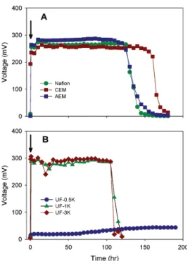
Fig. 3. Time-voltage curves of B-MFCs using (A) proton,
cation, and anion exchange membranes and (B) UF membranes. Arrow indicates acetate injection (1 mM at fi- nal) (Reproduced with permission from Kim et al., 16, Copyright 2007, American Chemical Society).
ductivity using the four-point probe technique in water.
Water uptake was measured by comparing dry and wet membranes and the surface morphology of microbial growth was tested using scanning electron microscopy.
Compared to the other research articles, Nafion-212 was used as the reference of commercial products rath- er than Nafion-117 which is more widely used. IEC of the synthesized membranes increased as the degree of sulfonation increased and was all higher than Nafion-212 (0.93 meq/g). The highest was 2.21 meg/q for BPSH 60. Proton conductivity also increased as the degree of sulfonation increased but BPSH 20 (0.039 S/cm) and BPSH 30 (0.066 S/cm) had lower con- ductivity than Nafion-212 (0.118 S/cm). The highest was 0.186 S/cm for BPSH 60. Water uptake of BPSH 60 was significantly higher (160%) than the rest of the samples and even Nafion-212 at 11.6% proving that the highest sulfonation was better for membrane characterization. Bacteria clustering on the membrane may cause biofouling leading to decreased performance of the MFC. Surprisingly, the least bacterial cluster oc- curred in BPSH 60 leading to the analysis that hydro- philicity has an impact in biofouling.
The performance of MFC incorporated with the syn- thesized membranes were analyzed in both two-cham- ber and single-chamber MFCs. Two-chamber MFC performance was analyzed in a continuous feeding sys- tem and voltage rapidly increased and peaked for all the samples but a rapid decrease followed right after showing that proton conductivity is highly susceptible to the cations related to microbial metabolism. For the single-chamber MFCs, performance was highly depend- ent on the PEM and BPSH 40 generated the highest voltage of 20 mV which was higher than Nafion-212 of 15 mV. This revealed that the membranes result in different activities in two- and single-chamber MFCs.
Because these membranes performed better in the sin-
gle-chamber MFCs, they seem to be a better alter-
native, specifically BPSH 40, for single-chamber MFCs
than two-chamber MFCs. Fig. 4 represents the pictorial
diagram of MFC membrane with Nafion membrane
[18]. SEM image of bacteria grown on the MFC mem-
Fig. 4. Two-chamber MFC used in this experiment: (1)
anode, (2) cathode, and (3) Nafion. The arrows indicate where the components are (Reproduced with permission from Chae et al., 18, Copyright 2008, American Chemical Society).
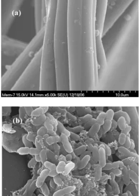
brane is shown in Fig. 5[18]. Picture of bacterial growth on the membrane after use of 50 days and SEM image is presented in Fig. 6[18].
To synthesize acid-doped polybenzimidazole (PBI) membranes, PBI, N, N-dimethyl acetamide (DMAc), and lithium chloride (LiCl) were reacted, filtered, and concentrated into a viscous solution[19]. The solution was then cast on glass plates and dried. Finally, the membranes were doped using phosphoric acid yielding about 500 mol% of doping. Because the synthesized membrane is incorporated in air-breathing MFCs, oxy- gen permeability was analyzed as well as the proton conductivity using a four-point probe measurement.
The lower the oxygen permeability, the better the per- formance of the MFCs. Pristine PBI membranes had a higher oxygen permeability than the commercial Nafion-117 membranes which negatively affects the performance of MFCs but PBI membranes doped with 500 mol% phosphoric acid showed a sharp decrease in oxygen permeability. Also, water uptake was lower than Nafion-117 for pristine PBI membranes but once it was acid-doped, it increased significantly. This was due to strong interactions of phosphoric acid and water
Fig. 5. SEM images: (a) new carbon felt and (b) bacteria