Manuscript received September 5, 2019, Revised September 27, Accepted October 21, 2019
1 KEPCO Research Institute, Korea Electric Power Corporation, 105 Munji-ro Yuseong-gu, Daejeon 34056, Republic of Korea
Development of Wind Turbine Simulation System Based on IEC 61400-25 Standard
Jae-Kyung Lee1†, Dong-Wook Kim1, Seok-Tae Kim1, Chang-Hun Chae1, Joon-Young Park1
Abstract
This paper introduces a wind turbine simulation system based on the IEC 61400-25 standard to simulate different kinds of wind turbines. A unified communication protocol was required for monitoring and control of wind turbines, because manufacturers had used their own protocols for their turbines. As a result of such an effort, the international standard IEC 61400-25 was established. To implement the schema of IEC 61400-25, the IEC61850 SCL was modified and applied to the simulation system, which enabled the system to be compatible with heterogeneous wind turbine information models. The developed simulation system can be used for interoperability tests with a new type of wind turbine information model.
Keywords: SCADA System, Wind Farm Operation System, IEC 61400-25
NOMENCLATURE SCL System configuration language.
IED Intelligent electronic device.
XML Extensible markup language.
DER Distributed energy resource.
LD Logical device.
LN Logical node.
ICD IED capability description.
SSD System specification description.
SCD System Configuration Description.
CID Configured IED description.
SMV Sampled measured value.
WTEC Remote wind turbine simulator controller.
WTE Wind turbine simulator.
RCB Report control block
I. INTRODUCTION
Wind power is not only a non-polluting natural energy without the risk of CO2 emissions or radiation leakage, but
also the most economic renewable energy, and accordingly, related markets are growing rapidly. With the recent growth of the wind power industry, there are active studies relating to the enlargement of wind turbines and development of offshore wind power farms.
Onshore wind power encounters difficulty in developing large onshore wind power farms because of the difficulty in securing a site for installation, the generation of noise, and civil complaints regarding damage to the natural landscape;
whereas offshore wind power has abundant wind resources and it is easy to secure a site for large offshore wind power farm development. With such benefits, offshore wind power is currently coming to the fore in Europe, and large offshore wind power farm development and related research are in progress. Compared to the onshore environment, the offshore environment is very suitable for wind power because of its high average wind velocity and its low wind change and turbulence depending on height or direction. In addition, wind turbines can operate at a higher speed because noise is not as much of a problem in the offshore environment as it is in the onshore environment and the tip speed of wind turbines, limited to about 60 m/s in the onshore environment, can exceed 100 m/s.
In particular, interest in offshore wind power has been higher since the start of Project Round 3 with a total of 45 GW in the UK in 2010, and the offshore wind power market is expected to be enlarged to 7 GW in 2020, amounting to about seven times the 1 GW in 2010. Keeping pace with the recent growth in the wind power farm market, many wind turbine manufacturers have been developing MW-size large wind turbines, and major shipbuilding companies have also been participating in the wind power farm project through the introduction of overseas wind turbine models or overseas wind power corporate takeover.
However, such active development of various wind power turbines causes issues not only with massive data processing but also heterogeneity and communications compatibility among wind power turbines due to the increase in the number and the size of wind power farms to be managed. With regard to the importance of heterogeneity of information models, it is desirable for large wind power farm operators to manage information from different types of wind power turbines that are installed in various wind power farms with the same format and the same platform in terms of farm operation efficiency. To satisfy such necessity of unified communications standards, the International Electrotechnical Commission has established the international standard, IEC 61400-25.
Next, another actual issue in developing wind power farms is smooth communication compatibility between wind
turbines that are installed in a farm and the SCADA system. It requires much time and expense for testing after the installation of wind turbines offshore, and accordingly, as the number of participant manufacturers and the size of wind power farms increase, the complexity of related works increases and there is a very high risk of the occurrence of stability-related problems because the complexity of related work increases. To sufficiently inspect system communications performance before inputting the SCADA system of a large wind power farm into the site, accordingly, the importance of a simulated environment similar to the actual wind power farm is increasing.
In this study, we have developed an IEC61400-25-based simulation system that can simulate a large wind power farm consisting of dissimilar wind power turbines in order to solve such operational problems in the wind power industry field.
The developed system has modified IEC61850 in order to apply IEC61400-25 to the wind power farm and can accept the data models of dissimilar wind power turbines by analyzing and investigating data acquired from various wind power farm SCADA systems. The developed system has been designed to also test interoperability between a wind power turbine and the SCADA system.
II. CONSIDERATION FOR WIND POWER SIMULATION 1) Scalability: Wind power turbine simulation involves the calculation of external environmental changes such as wind direction and wind velocity per wind power farm, operating conditions of wind power generator, calculation of wind power turbine outputs and calculation of influences of surrounding environment based on the operating conditions.
Such simulation work is carried out by using ordinary computers or specific devices. The required computer performance is determined according to user requested simulation precision and the quantity of target wind power turbines. Accordingly, the simulation work for large wind power farms needs a plan for building a high performance simulation system at a low cost because high performance computer resources (CPU, Memory, HDD, Network) are required.
2) Heterogeneity: In general, the cost for construction of offshore wind power farms is 1.5 times higher than onshore wind power farms because of installation construction expenses and generated power transmission to the shore, and the development of large offshore wind power farms has many difficulties in terms of time and cost. Accordingly, the construction of large wind power farms is conducted under a long-term construction plan by reflecting cost-related or strategic consideration.
This point increases the possibility of inclusion of heterogenic factors in terms of functional or physical characteristics among wind power generators to be introduced in constructing a large offshore wind power farm.
Due to the massive number of wind power generators needed,
Fig. 1. Offshore wind power farm [1].
Fig. 2. Round 3 consortia for developing UK offshore wind power farm [2].
to construct a large offshore wind power farm with the same product model, and new wind power generators can include any heterogenic factor by being compared with the previously introduced wind power generators, even though those are manufactured by the same manufacturer, because of a long construction period and manufacturers’ continuous development. Accordingly, solving the heterogeneity among wind power generators in the same wind power farm is one of the important issues.
Accordingly, wind power farm simulation should support the function of simulating diverse wind power turbine characteristics, and there is also the need for an environment where the configuration information of simulated wind power turbines can be managed.
3) Real-time Processing: The wind power farms being scattered around the wide offshore area need a transportation system, such as special ships, in order to handle any mechanical failure or malfunction of the wind power turbines during operation. There are cases in which approaching wind power turbines by special ship is impossible depending on the weather situation. In case of the addition of a new wind power turbine or a change of the control system, additional work is frequently generated in order to satisfy the communications environment of existing systems. Considering the difficulty in approaching the offshore wind power farm, accordingly, the importance of a testbed is increasing in order to examine new functions and improvement work of the wind power farm operating system.
The testbed needs a real-time processing function that can process operating data and control the request for the target wind power farm operating system according to external environmental changes and wind power turbine operation conditions defined by the tester.
III. MODEL BASED ENGINEERING WITH SCL IEC 61400-25 structuralizes wind power turbine data and describes related communications services, but it does not define the environment for data transmission in a wind power farm, consisting of many wind power generators and the SCADA system, and the environment for operating each wind power generator. XML-based definition methods for wind power farm environment configuration are currently being suggested to solve the problem, but such methods are as yet unverified in the actual operable environment and there is no related SW solution. In this study, accordingly, IEC 61850 SCL was applied for the modeling of wind power turbines and wind power farms. IEC 61850 defines SCL notation in order to conduct digital substation environment configuration based on international standards for digital substations [3]. In addition, IEC 61850 defines SCL notation for environmental configuration among many Logical Devices and describes the connection among IEDs having different functions. For these reasons, the IEC 61850 SCL can be applied to this system after being extended. There is no case
of SCL being applied to wind power farms so far, but the possibility of using SCL was examined by modeling the virtual wind power farm emulator with SCL because the wind power farm environment is similar to the aggregation of diverse IEDs being used in digital substations.
A. SCL Engineering
SCL Engineering is commonly defined as processes to be modified to represent real-world information models and to operate the structuralized information models in IEDs.
Accordingly, IEC 61850 uses XML-based substation configuration language, and SCL is defined in IEC 61850-6.
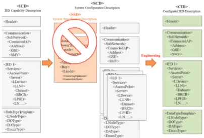
XMLs are classified into document-centered XMLs and data- centered XMLs. The data-centered XMLs efficiently describe data and configuration information by using a tree structure and provide high quality structural information. SCL was recently renamed “System Configuration description Language" (formerly Substation Configuration Description Language) so that it can be applied to DER (Distributed Energy Resource), Wind Turbine, Hydropower, etc. Fig. 3.
shows an example of digital substation configuration using SCL.
SCL files describe every configuration for communication among IEDs or wind power turbines. In particular, the SCL file structuralizes and represents IED data, and it describes substation configuration and connection among IEDs. In addition, it describes IP address, Subnet mask, etc., necessary for communication, and it also contains data operation and initialization such as Configuration Data and Dataset for report generation of IEDs. Accordingly, SCL files should be created and how to operate service and data should be described in order to apply the SCL files to description of virtual wind power farms.
SCL files are classified into four different types according to usage. IED data are defined as Data Object such as LD and LN and data are structuralized. There are ICD files describing data operation method functions by using Dataset and Control Block. SSD files structural information among IEDs or Networks, and can be described as Ladder Logic where each LD is shown. SCD files contain the entire system/substation configuration information, and which can set
Fig. 3. Data based XML [4].
communications among IEDs. CID files show specific data, parameters, etc., of IED, and which are used to transplant SCD file information into each IED.
B. SCL Engineering Modification
Fig. 4 shows the process of SCL engineering. The System Configurator configures the function of each IED by using SSD files and ICD files and creates an SCD file specifying data flow.
The IED Configurator extracts the CID file of an individual IED from the SCD file and the extracted CID file is uploaded through communication among IEDs.
The ICD file contains header information to show IED functions, simple communication information and the contents of Data Type Templates. The SSD file contains substation items that are substation configuration information. The SCD file, a consolidation of ICD and SSD files, contains detailed communication information and
information on Dataset and Control Block. Finally, the CID file contains specific data and parameters of each IED.
However, there is a slight difference in the SCL engineering process between the wind power system and the substation system. The SSD files can be omitted because there is no need of substation information showing substation configuration information, and actually there is no big difference in the contents of ICD files and SCD files. In other words, the SSD files can be omitted because the general system configuration is not expressed with a single line diagram where each logical node is shown. Fig. 6 shows an engineering process describing the SCL files in wind power.
SCL engineering is largely divided into Edit work and Engineering work. As shown in the figure below, the Edit work is mainly used to create ICD files and is provided by the IED manufacturer. Communications, such as Mac Address, IP and Subnet Mask, are set, and Logical Device and Logical Node are set. In addition, Report Control Block, GOOSE
Fig. 4. Sequence of IED engineering.
Fig. 5. SCL file on IEC 61850 [5][6].
Fig. 6. SCL File structure on IEC 61400-25[7].
Table 1 SCL Files
File Description Type of Work Remark
ICD - Functions of IED
defined dataset such as logic device and logic nodes, control block
- Mandatory submission by the manufacturer
IED
Specification IED Capability Description
SSD - Information on substation structure - System specifications
Overall system configuration is shown with a single line diagram where each logistic node is described.
System Specification
System Specification
Description
SCD - Substation configuration This shows the flow of substation
automation configuration data.
- System configuration description file Setting communication among substation
IEDs using the ICD file
System
Engineering System Configuration
Description
CID - Specific data, parameters, etc., of IED This is a file to format SCD information
for each IED.
IED
Configuration Configured IED Description
Control Block and SMV Control Block can be set[6]. Unlike substation, however, there is no communication among turbines and Merging Unit in wind power, so GOOSE Control Block and SMV Control Block are not used and only Report Control Block is used. Accordingly, the wind power engineering work can be classified into IED Edit, in which IED functions are defined by the manufacturer, and System Engineering, in which communication among IEDs is set.
System Engineering can be divided into three works in detail:
setting basic information and communication information of IED, setting Dataset and setting Control Block. IEDs communicate with the upper system through TCP/IP-based MMS communication. Accordingly, settings for TCP/IP and MMS communication are necessary. Next, the Dataset for communication is controlled. In the Report communication, data transmission is conducted by using the Dataset defined herein. Finally, the Control Block should be created and set so that IEDs can transmit data through communication. An SCD file with the Engineering work completed is converted into a CID file and is applied to an individual IED.
IV. DATA MODELING & STRUCTURATION BASED ON IEC 61400-25
A wind turbine contains a momentum converter, which absorbs and converts energy from wind, a power transfer unit and a controller. Each component cannot function individually and can only perform its functions as an overall system after being interconnected. A substation also has complicated devices, and to express them in the virtual world, the actual devices inside the substation are virtualized in IEC 61850. A single bay is shown as LD and each function existing in the bay is shown as LN. Fig. 7 shows the basic concept of IEC 61850 substation modeling.
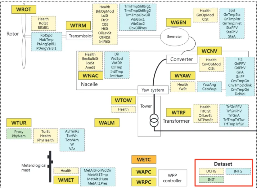
IEC 61400-25, like IEC 61850, shows wind turbine devices as shown in Fig. 8. Wind turbines are virtualized and are expressed as a single LD in the virtual world, and diverse turbine components and functions are expressed as LN. Such logical configuration of wind power generators is called the Information Model, and about 20 LNs are defined in IEC 61400-25.
IEC 61400-25 consists of WTUR, which indicates general information of wind power; WALM, which indicates Alarm information; WMET, which indicates meteorological information; WAPC and WRPC, which indicate active and reactive power control information; WROT, which indicates Rotor information; WTRM, which indicates generator information; WYAW, which indicates Yawing system information; WCNV, which indicates power converter information; WNAC, which indicates Nacelle information; and WSLG, WALG and WREP, which indicate status, analog log and report information. It also contains MMXU, XCBR, etc., which are covered in IEC 61850 7-4. Fig. 9 shows the Information Model modeled in the wind turbine.
In the wind turbine emulator, the kinds of data generated from the wind turbine were designed to be divided into data with transition of state value, analog data, data with no ordinary monitoring required and control data for reception.
In addition, data objects that should be received for each LN were designed to be reported by using a dataset. Each dataset configures Measured Dataset, which aims at receiving data per hour, configures State Dataset whenever the state of the wind turbine is changed, and configures Report Control Block
Fig. 7. Logical node defined at IEC 61850 [8].
Fig. 8. Logical node defined at IEC 61400-25 [9].
Fig. 9. IEC 61400-25 logical node [10].
by using Buffered Report Control Block and Unbuffered Report Control Block. In this model, in addition, modeling was conducted after expanding IEC 61400-25 by using WPRV LN to accept the data that the wind power farm operator desires to receive. Fig. 10 shows the configuration diagram of the data that are received from the wind turbine emulator by using the dataset and report control.
V. CLUSTERING COMPUTING FOR WIND TURBINE SIMULATOR
As wind power farms are becoming larger, the importance of the wind power farm operating system, which immediately relays the operation and actual system of the wind power farm, is growing. However, there are difficulties in securing functionality and stability because the SCADA system development method for operating existing small
wind power farms has been applied to the development of a system to operate large wind power farms. For this reason, a testbed is required to inspect and support the target wind power farm in a simulated environment that is similar to actual wind power farms.
The current research on the wind power generator simulator is being conducted for the purpose of checking transients of the wind power system and the wind power system’s influences on surrounding systems’ electrical quality and protection systems, and determining the wind power system’s characteristics, prior to connecting the actual individual wind power generator to the system. Accordingly, the existing simulator requires a wide space and high cost structure in order to simulate specific circumstances of large wind power farms.
If the inspector who desires to inspect the operating system defines the size of a wind power farm, the simulator transfers data for testing by virtually simulating wind generators as according to the defined farm size to the target
Fig. 10. Virtual wind turbine simulator data point
SCADA system by using diverse communication protocols (OPC, Modbus, MMS) [8].
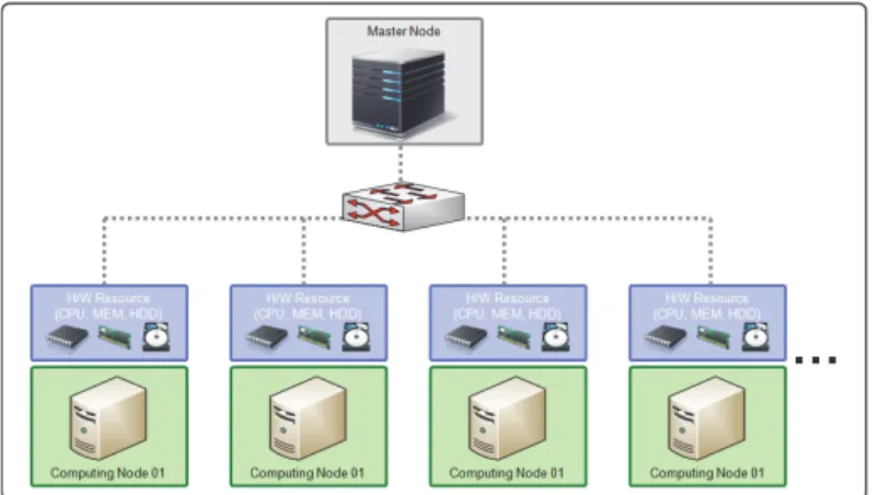
It is impossible to simulate a large wind power farm consisting of many wind turbines in a single system because of H/W resource (CPU, Memory, HDD, Network) performance limit in one system. To solve this problem, clustering computing technology, which increases the overall computing performance by linking many low-priced computers in a single computing group, has been applied. The cluster system consists of one Master node computer, which controls wind power farm simulation, and many Computing nodes, which actually perform the simulation work. The clustering computing technology, in case of insufficient computing
resources, features scalability enabling the simple addition of a new computing node system to simulate a larger wind power farm without correction of the entire S/W source code.
VI. IMPLEMENTATION
This chapter shows the Wind Turbine Simulation System.
Wind turbines operate the wind turbine operating system and transmit/receive data by using diverse protocols per manufacturer. IEC 61400-25-4 defines service mapping with IEC 61400-25-3 through 60870-5-104, DNP3, OPC, MMS and SOAP-based Web services protocols. With regard to MMS and Web services, particularly, IEC 61400-25-4 supports all services defined in IEC 61400-25-3, whereas MMS shows faster data transmission/reception by using Binary communication compared to the Web services using XML communication. In this system development, Wind Turbine Simulator System has been developed using MMS.
The overall system consists of one wind turbine operating system that functions as an IEC 61400-25 client and 500 wind power generators that function as an IEC 61400-25 server. Fig. 13 shows the overall configuration of the Wind
Fig. 11. Simulator for testing a SCADA system.
Fig. 12. Cluster computing configuration.
Fig. 13. Overall structure of wind turbine simulator & SCADA simulator system.
Table 2
Mapping overview of IEC 61400-25-3 services Mapping Capability Overview
IEC 61400-25-3 Services M/O Web Services OPC
XML- DA
IEC 61850
-8-1 (MMS)
IEC 60870 -5-104
DNP3
Associate M Y Y Y Y Y
Release O Y Y Y Y N
Abort O Y Y Y N N
GetServerDirectory O Y Y Y N Y
GetLogicalDeviceDirectory O Y Y Y N Y
GetLogicalNodeDirectory O Y Y Y N N
GetDataValues M Y Y Y Y Y
SetDataValues M Y Y Y Y Y
GetDataDirectory O Y Y Y N N
GetDataDefinition M Y Y Y N N
GetDataSetValues O Y Pa) Y N Y
SetDataSetValues O Y N Y N Y
CreateDataSet O Y N Y N N
DeleteDataSet O Y N Y N N
GetDataSetDirectory O Y N Y N N
Report O Y Y Y Y N
GetBRCBValue O Y N Y N N
SetBRCBValue O Y N Y N N
GetURCBValue O Y N Y N N
SetURCBValue O Y N Y N N
AddSubscription O Y Y Y N N
RemoveSubscription O Y Y Y N N
GetLCBValues O Y N Y N N
SetLCBValues O Y N Y N N
GetLogStatusValues O Y N Y N N
QueryLogByTime O Y N Y N N
QueryLogAfter O Y N Y N N
Select O Y Y Y Y Y
SelectWithValue O Y Y Y Y Y
Cancel O Y Y Y Y N
Operate M Y Y Y Y Y
CommandTermination O Y Y Y Y Y
TimeActivatedOperate O Y Y Y N N
a) The level of support is further described in B.5.7.3.5.
Turbine Simulator System and Wind Farm Operation System Simulator, and in this study, it describes the Wind Turbine Simulator System and IED Server using MMS. The Wind Turbine Simulator System consists of a Wind Turbine Simulator (WTE) and Remote Wind Turbine Simulator Controller (WTEC) to control each simulator, and it performs communication/control between WTEC and WTE using self- defining protocols.
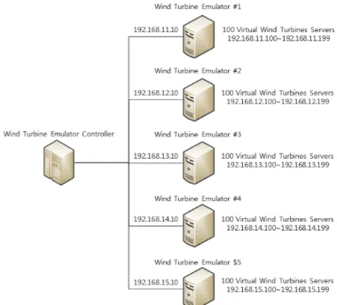
A. WTEC (Remote Wind Turbine Simulator Controller) The WTEC functions as a monitor and a remote controller of the Wind Turbine Simulator, and it monitors the usage of physical resources of the Wind Turbine Simulator. WTEC enables WTEs to operate in different environments by editing the data model and network configuration information of each WTE, and it transmits and receives the operation state of each WTE (start/end/control) by using separate communication protocols. Fig.14 shows the diagram of network connection between the WTEC and physical WTE servers.
B. WTE (Wind Turbine Simulator)
The WTE, which aims at virtual wind power farm configuration, collects and outputs system resource data, and it also creates a Wind turbine information model and MMS Server Dictionary by receiving an Agent Process controlling the Simulator Process and the received configuration files.
The WTE consists of Simulator Process (MMS, OPC, DNP, Modbus) in which data transmission/reception is conducted along the network protocols set after data simulation. Fig. 16 shows the GUI of WTE shown in WTRC.
1) Physical server of wind turbine emulator a) Connect WTE Agent using IP&Port
b) Physical resource monitoring of WTE Agent c) Select a group of WTE in WTE Agent 2) Individual wind turbine emulator selection
a) Status section shows IED&LD name, Network configuration, Manufacturer
b) Control section
i) Model type: Communication protocol(MMS, OPC, Modbus)
ii) Algorithm: Static, Increment, Decrement, Simulation, Algorithm
iii) Wind Turbine Control: Start, Stop, Reset, Ready c) Configuration
i) Choose path of information model(ICD file) 3) Emulator control section: Controls START/STOP of a
group of WTEs
4) Usage of Physical resources are shown: CPU, Memory, Storage, Network
5) IEC 61400-25 LNs of a wind turbine emulator
6) Detailed data of modeled DOs including CDC information
7) Simulation data generation control under DAs 8) Monitoring lists of DAs
9) Wind turbine emulator agent
a) Load Configuration: Receive WTE configuration and configure virtual WTE’s model
b) Controls individual wind turbine emulator operation
c) Shows wind turbine emulator configuration data d) Transmit simulation command to selected WTE 10) Assigns virtual IPs on wind turbine emulator 11) Log message box
A physical wind turbine simulator can create more than 100 virtual wind turbine simulators. In the early stages of development, the configuration of a virtual wind turbine simulator was attempted by using a multithread method. In creating 100 emulators, however, 3 GB memory is required because one simulator uses about 30 MByte of memory. x86- based 32 bit process can use only 2 GB User Address Space.
Fig. 14. Detailed network diagram for wind turbine simulation system.
Fig. 15. Communication packet on wind turbine simulation system.
To solve this problem, WTE offers Multi-Process type services. Each agent uses named pipe for communication among processes by creating, destroying and state- monitoring child-processes. In addition, a multi-thread queue is necessary when a massive amount of data is transferred to the process. There is performance degradation because a lock is used for queue input/output synchronization under the multi-thread environment. Accordingly, for massive data processing, a lock-free type queue, which has fast processing
speed by using atomic instruction, was chosen to ensure thread safety at the CPU level.
VII. VERIFICATION OF VIRTUAL WIND TURBINE SIMULATOR
In order to verify Wind Turbine Simulator, we simulated a virtual wind power farm which consists of 500 virtual wind turbines and tested stability, and performance of the simulator. Table 3 shows the specification of servers used for verification.
The testing environment is comprised of five WTE and a WTEC. Each WTE is in charge of creating 100 virtual wind turbines for building virtual wind power farm comprised of total 500 wind turbines. The following figure shows a list of virtual wind turbines managed by a WTE. All of the virtual wind turbines in the above figure are controlled by WTEC on a remote site. The following figure shows the screen that WTEC manages all virtual wind turbines. Users can control all
(a) (b)
(c) (d)
Fig. 16. GUI of wind turbine simulator & controller. (a) Monitoring use of resource of each wind turbine simulator machines. (b) Monitoring individual wind turbine data generation. (c) LNs, DOs of a virtual wind turbine simulator. (d) Control GUI of wind turbine simulator agent.
Table 3 Specification of Servers
Environment of Server Num.
WTE
OS Windows 2008 server
CPU Intel Xeon E5-2640 5ea Memory 8 GB
HDD 300 GB × 2 ea WTEC
OS Windows 2008 server
CPU Intel Xeon E3-1270 1ea Memory 4 GB
HDD 300 GB × 2 ea
virtual wind turbines on the graphic user interface of WTEC.
In order to measure the performance, we build a test environment that all of 500 virtual wind turbines produce a value per a second and send the values to WPFM using RCB of IEC61400-25.
Under the test environment, we measure the time taken to send values from virtual wind turbines to WPFM. The following table shows the measurement result of transfer time from a virtual wind turbine to WPFM during 24 hours.
There were 83,986 data transfer in the testing.
VIII. CONCLUSION
In this study, an IEC 61400-25-based Wind Turbine Simulation System was developed to solve information model heterogeneity and communication compatibility among wind turbines, which are issues in the development of the SCADA system for large wind power farms. In this system, we conducted modeling on an IEC 61400-25-based wind turbine data structure by expanding or correcting IEC 61850 SCL, which is used for digital substations. Since a wind power farm consisting of many heterogeneous wind turbines can be simulated by using the turbine information model constructed as above, a simulated environment to sufficiently inspect the communication performance of the SCADA system for large wind power farms can be provided prior to direct input of the system to the field using the turbine information model. In addition, the system also offers an environment where communication compatibility of heterogeneous wind
turbines, which are to be installed in wind power farms, can be inspected through the SCADA simulation function in advance. The developed simulation system will be applied to the development of the SCADA system and wind turbines for the future southwest offshore wind farm test site, and it is expected that prior performance inspection of the SCADA system and wind turbines will greatly contribute to decreasing the wind power farm construction period and improving the stability of wind power farm operation.
ACKNOWLEDGMENT
This work was supported by the New & Renewable Energy Program of the Korea Institute of Energy Technology Evaluation and Planning (KETEP) grant funded by the Korea government Ministry of Knowledge Economy under Project No. 2011T100100307.
REFERENCES
[1] KIEE, “Wind turbine technology research reports,” Seoul, KIEE, 2010.
[2] Crown Estate, http://www.thecrownestate.co.uk/
[3] IEC 61850-6:2009 – Configuration language for communication in electrical substations related to IEDs, International Electrotechnical Commission.
[4] IEC 61850-5:2013 – Communication requirements for functions and device models, International Electrotechnical Commission.
[5] IEC 61850-7-1:2011 – Basic communication structure – principles and models, International Electrotechnical Commission.
[6] IEC 61850-7-2:2010 – Basic communication structure – Abstract communication service interface(ACIS), International Electrotechnical Commission.
[7] IEC 61850-7-3:2010 – Basic communication structure – Common Data Classes, International Electrotechnical Commission.
[8] IEC61850-7-1:2006 – Communication networks and systems in Fig. 17. System structure for testing environment.
Fig. 18. Screenshot of WTSP.
<ReportControl name=”brcbMX” datSet=”WTUR_AI” intgPd=”0” rptID=””
ConfRev=”1” buffered=”true” bufTime=”0”>
<TrgOps dchg=”true” qchg=”true” dupd=”true”/>
<OptFields seqNum=”true” timestamp=”true” reasonCode=”true” dataset=”ture”/>
<RptEnabled/>
</ReportControl>
Fig. 19. RCB setting of virtual wind turbines [3].
set WT0001LDWT0001/WYUR$1MX$VAr$i 100 integer 2 1 30 set WT0001LDWT0001/WYUR$1MX$mag$i 100 integer 2 1 30 Fig. 20. Simulation configuration of virtual wind turbines.
Table 4
Performance Measurement of Testing Transfer time(s)
Average 0.387
Max 1.610
Min 0.310
substations – Part 7-1: Basic communication structure for substation and feeder equipment – Principles and models Reference, International Electrotechnical Commission.
[9] IEC61400-25-1:2006 – Communications for monitoring and control of wind power plants– Overall description of principles and models,
International Electrotechnical Commission.
[10] IEC 61400-25-2 – Communications for monitoring and control of wind power plants-Information models, International Electrotechnical Commission.
![Fig. 2. Round 3 consortia for developing UK offshore wind power farm [2].](https://thumb-ap.123doks.com/thumbv2/123dokinfo/4900065.291393/2.961.65.467.246.546/fig-round-consortia-developing-offshore-wind-power-farm.webp)
![Fig. 8. Logical node defined at IEC 61400-25 [9].](https://thumb-ap.123doks.com/thumbv2/123dokinfo/4900065.291393/5.961.67.448.81.357/fig-logical-node-defined-iec.webp)

![Fig. 19. RCB setting of virtual wind turbines [3].](https://thumb-ap.123doks.com/thumbv2/123dokinfo/4900065.291393/10.961.67.467.270.481/fig-rcb-setting-virtual-wind-turbines.webp)
