Detection of Manufacturing Defects in Stiffness of CFTA Girder using Static Loading
김 두 기† 나뎀 파레즈* 취진타오** 박 경 훈***
Kim, Dookie Alfahdawi, Nathem Cui, Jintao Park, Kyung-Hoon
···
요 지
새로운 형태의 교량 거더인 CFTA(Concrete filled and tied tubular steel arch) 거더의 비선형 거동에 대해 고찰한 후, CFTA 거더의 대량 공장 생산시 콘크리트 충진 불량으로 발생할 수 있는 결함인 거더 안의 빈 공간을 탐지하는 새로운 방 법을 제안하였다. CFTA 거더 안의 비대칭성 콘크리트 충진 불량 결함을 구조물의 대칭 거동을 이용하여 탐색하였으며, 수 치해석과 실험을 통해 제안된 방법을 검증하였다. 제안된 방법을 수치적으로 검증하기 위해 3차원 유한요소모델을 사용하 였으며, 실험적으로 검증하기 위해 CFTA거더의 정적 실험자료를 사용하였다.
핵심용어 : CFTA 거더, 정적재하, 제조결함, 대칭성
Abstract
This paper presents a study on the nonlinear behavior of an innovative bridge girder made from concrete-filled and tied tubular steel arch (CFTA) under static loading. Manufacturing of the CFTA girder may have defects which may highly affect the symmetry and performance of the structure. A simple method is proposed by using stiffness extracted from static test data to detect manufacturing defects of the CFTA girder. A three-dimensional finite element model was used in the numerical analysis in order to verify the method. The proposed method was experimentally validated through static tests of the CFTA girder. The application of the proposed method showed that it is effective in identifying invisible manufacturing defects of the CFTA girder, especially for mass production of a standard type in the factory.
Keywords : CFTA girder, static loading, manufacturing defect, symmetry
···
†책임저자, 종신회원․군산대학교 토목환경공학부 부교수 Tel: 063-469-4770 ; Fax: 063-469-4791 E-mail: [email protected]
* 삼성엔지니어링 과장
** 군산대학교 토목환경공학부 박사과정
*** 한국건설기술연구원 수석연구원
∙이 논문에 대한 토론을 2012년 4월 30일까지 본 학회에 보내주시 면 2012년 6월호에 그 결과를 게재하겠습니다.
1. Introduction
Concrete filled tubular steel(CFT) structure is a typical steel-concrete composite member, which has high load-bearing capacity and other good structural performances, such as high ductility and energy dissipation ability, due to the composite action between steel and concrete in the member(Lu et al., 2009). CFT constructions have advantages over whole steel tube members and reinforced concrete
members. The in-filled concrete delays local buckling of the steel tube and the steel tube reinforces the concrete to resist tension, bending moment, and shear force. The tube also acts as a formwork for the concrete during construction of the bridge, thus saving a major construction cost (Roeder et al., 1999; Varma et al., 2002). The high tensile strength and ductility of the steel component can be utilized using CFT with the advantages of compre- ssive strength and stiffness of concrete(Trung et
al., 2008; Jeong et al., 2009; Roh et al., 2011). As steel plates are combined with concrete, the resistance against buckling increases and eliminating heavy stiffening, which make composite bridges more economical and competitive compared to a typical concrete bridge. In addition, the steel/concrete composite bridges are lighter, guarantee better quality and have easier and faster erection than conventional concrete bridges (Chaudhary et al., 2007; 2009, Choi, 2008; Chou, 2008). The composite bridges are also expected to reduce noise and vibration levels and are therefore environmentally friendly (Nakamura et al., 2002). The CFT structural members have a number of distinctive advantages over conventional steel reinforced concrete members. CFT members provide excellent seismic resistance in two orthogonal directions as well as good damping characteristics (Elchalakani et al., 2001). CFT has high resistance against bending moments and compressive axial forces and are ideal as arch ribs (Nakamura et al., 2008). The steel tube not only takes axial load, but also provides confining pressure to the concrete core, while the concrete core takes axial load and prevents or delays local buckling of the steel tube (Huang et al., 2002).
In this study, a new type of bridge girder is discussed that can maximize the structural efficiency by combining CFT structure, arch structure, and pre-stressing structure. The type of girder is called concrete-filled and tied tubular steel arch (CFTA) that can be made to long span with light weight. It is structurally stable with small amount of material and maintenance. The CFTA bridge girder has many advantages compared to the typical bridge girder structures because it makes use of almost all the prominent characteristics of each material and structural design, including buckling prevention by concrete filling, a higher stiffness and durability due to the confinement effect, a longer span and lighter structure due to pre-stressed tendons, as well as the pleasing aesthetics of an arch shape (Lee et al., 2008). In addition, this bridge girder has a good resistance to reduce the moment by ways of an arch
shape and pre-stressing force and to induce compressive force to compensate for tensile stress.
The CFTA girder should be produced in mass in the factories, since field construction is not available. However, the manufacturing defects, e.g.
the voids between filled concrete and steel tubular, have a significant effect on the symmetry and performance of the structure. It may be noted that the defect due to voids is not visible as compared to the defect in other types of structures. In this paper, a methodology to quantify the manufacturing defects of CFTA and nonlinearity of the structure is presented by using stiffness data extracted from simple static loading tests. Finite element (FE) analysis and static loading tests on a real CFTA bridge girder model were performed to validate the proposed method. The proposed method seems to have potentials in verifying manufacturing defects of CFTA girder, especially in case of mass production of the standard type in the factory.
2. Description of the structure
The bridge under consideration is a composite system of CFTA bridge girder that consists of a steel surface, concrete arch, tendons, and concrete deck components. In order to transfer the self-weight of concrete to the arch rib after manufacturing the steel surface of girder with arch shape, column concrete is filled so that the composition of steel and concrete is completed with empty space inside of steel surface.
In addition, the pre-stressed tendons which are located in the lower part of composite girder ends are installed to compensate loads effectively. This bridge with the span of 25.6m is located at Korea Institute of Construction Technology (KICT), Ilsan, SouthKorea.
The tubular steel arch is composed of steel plates with different thicknesses, among which, the thickness of the middle part of each top and lower flange is 22mm, the thickness of steel plate cover at the end of the girder until the middle part of flanges is 12mm, and the thickness of each side of the girder is 10mm. The slab is 3.5m in width and 0.24m in
(a)
5 m 3 m 3 m 5 m 4.1 m
4.1m
25.6 m
0.3 0.4 0.4 0.3
DT-0
DT-1 DT-2 DT-3 DT-4 DT-5
DT-6 Filled concrete Voids
(b)
Filled oncrete
Voids
Filled concrete
Voids
Filled concrete
(c) (d) (e)
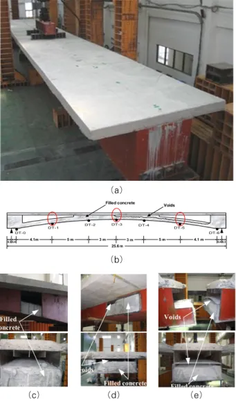
Fig. 1 CFTA girder: (a) Overview, (b) Schematic of girder with voids, (c)-(e) Experimental defect model
at location DT-1, DT-3 and DT-5
thickness. The edges of girder are connected by 4 pre-stressed tendons in the longitudinal direction, with cross section area of 1664.4mm². The cross section of girder is 1.5m in width and 1.5m in depth.
3. Detection of manufacturing defects in the girder
Manufacturing defects may cause the structure unsafe and usually are invisible, in which void is one of the main defects in the stiffness change. One of the engineering challenges is filling the complex steel tubes with concrete without any voids to make the structure more efficient. Fig. 1 shows the voids inside and along the CFTA girder that existed during pouring of the concrete into tubular steel.
The voids have a significant effect on the static behavior of CFTA girder and symmetry of structure as well. There are many factors that affect on the presence of the voids inside the girder such as the density of filled concrete and the shape of the girder.
The stiffness calculation is utilized to detect the voids inside CFTA girder as following:
∆∆ (1)
where is the stiffness at each measured point, 1,2.3,… is the number of load steps, ∆ is the difference between each sequence load and
∆ is the difference between displacements with the same position at each load step.
The method to detect voids of the structure is presented in order to determine the manufacturing defects. In other words, this method is important to verify the integrity of the structure after construction in order to localize the voids inside the girder. The procedure to perform the detection is based on the difference of stiffness between the first and last load steps or total stiffness for all load steps at each measured point as given in the following equations:
∆ (2)
∑ ⋯
where ∆ is the difference between the high and low stiffness, and are the first and last load steps respectively, and are the displa- cements extracted from the first and last load steps respectively and ∑ is the summation of stiffness for all load steps.
4. Numerical simulation
4.1 Finite element modeling
The 3D FE model of the CFTA bridge was constructed using the structural software Strand7, which involve four main components as shown in
Component Density (kg/m³)
Young's Modulus(MPa)
Poisson's Ratio
Slab 2500 18800 0.167
Filled concrete 2500 27223 0.167
Steel plates 7850 210000 0.3
Tendons 8000 210000 0.3
Table 1 Material properties of bridge Fig. 2 Numerical model of the girder
0.0E+00 5.0E+06 1.0E+07 1.5E+07 2.0E+07 2.5E+07 3.0E+07 3.5E+07 4.0E+07
0 0.001 0.002 0.003 0.004 0.005
S t r a i n (m/m)
Stress (Mpa)
filled concrete
Yield stress Max FEM stress
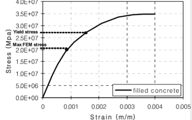
Fig. 3 Analytical stress-strain diagram of concrete
0.0E+00 2.0E+06 4.0E+06 6.0E+06 8.0E+06 1.0E+07 1.2E+07 1.4E+07 1.6E+07 1.8E+07
0 0.001 0.002 0.003 0.004 0.005 S t r a i n (m/m)
Stress (pa)
s lab
Yield stress
Max FEM stress
Fig. 4 Analytical stress-strain diagram of slab Fig. 2. It may be noted that there is hollow space
holding the concrete inside the steel tubular, which can create a very efficient composite section. For the pre-stressed tendons, two inside tendons have 883.61MPa pretension stress and two outside tendons have 443.82MPa pretension stress. The FE model of the bridge is composed of 6560 solid elements, 3668 shell elements, 12 beam elements and 9243 nodes. Table 1 shows material properties of the CFTA girder model. Analytical displacements of the corresponding nodes at the same monitored points with the test specimen were obtained by static analysis.
To simulate the nonlinear behavior of the CFTA bridge girder, the stress-strain curves for concrete and slab are used. All empirical equations available to predict the stress-strain curves proposed by Ahmed et al. (1982) are used here to determine the stress-strain characteristics for slab and filled concrete, which can be represented by the following equations:
(3)
where and are parameters that describe the ascending and descending parts of the stress-strain curve. They are given as follows:
(4)
× × ′
where and are as defined previously, is the axial strain at the stress state , and
is as given by with ×
′. The octahedral shear stress is given by
.The compressive stress-strain curve for FE analysis is defined using Eq. (3). In order to
specify yield stress, the Chord method (Kosteski et al., 1999) is conducted. Figs. 3 and 4 show the stress-strain curves of filled concrete and slab, respectively. The maximum FE stress for filled concrete and slab are lower than the yield stress, which proves that the FEM analysis is in the
Fig. 5 Analytical displacement curves for intact, right defect and left defect FEM
0.0 5.0 10.0 15.0 20.0 25.0 30.0
DT-1 DT-2 DT-3 DT-4 DT-5
No. of measured points
K(N/m)×106
K1 kN K2 kN K3 kN K4 kN K5 kN
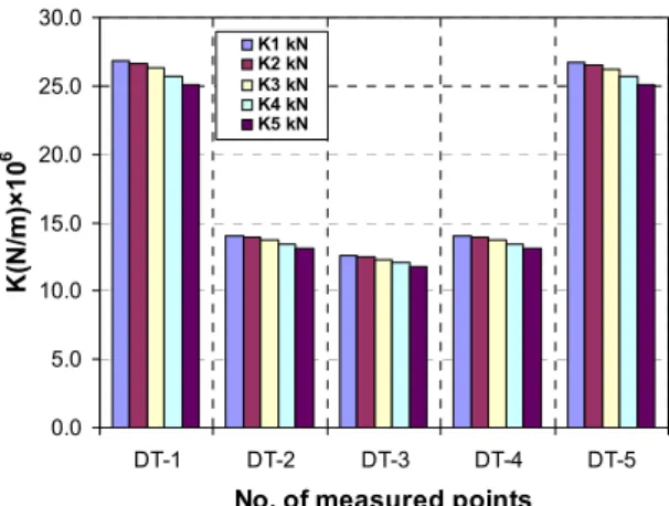
Fig. 6 Numerical stiffness at measured points
Fig. 7 Comparison of intact and defective FE models elastic range.
To show the performance of the proposed method, three analytical models with different locations along the girder are estimated, among which the first model is intact model, the second model considers the voids located in left side and the third model considers the voids located in right side of girder.
From those three models the displacements are extracted by applying 298kN as the maximum load and they are compared as shown in Fig. 5. The displacement curves of the defect model show that the deflection at defect side is higher than the intact side. And the intact model shows the symmetry behavior with less deflection and higher stiffness.
Since the intact model is available in numerical simulation, the symmetric defects of the girder can be detected by comparing with the intact model.
4.2 Manufacturing defects detection
Eq. (1) is used to calculate the numerical stiffness from FEM as shown in Fig. 6, from which one can note the reduction of stiffness at each point with the increasing load step proves the nonlinear behavior of the CFTA girder.
The numerical verification procedure is performed by applying the nonlinear static analysis for each intact and defective FE model. The intact FE model is represented by the tubular steel fully filled with concrete and the defective FE model is conducted by removing some elements from the left part of
CFTA girder. Fig. 7 shows the numerical results of total stiffness for intact and defective FE models.
The comparison shows that the proposed method is effective in detecting the manufacturing defects of the CFTA girder.
5. Experimental study
In order to specify the static behavior of CFTA girder, a prototype was constructed and tested.
According to the design guidelines, the most important parameter that has to be measured during the experimental test is the vertical displacement of the bridge, especially until service load by taking consideration of the requirement of the guidelines for a maximum permissible deformation (Giannopoulos et al., 2003). The vertical displacements were measured at five locations along the specimen by seven displacement transducers. The numerical displacements
Fig. 11 Experimental stiffness differences
Fig. 12 Total experimental stiffness for all load steps
0 5 10 15 20 25 30
0 5 10 15 20 25
Displacement (mm)
Loads (kN)
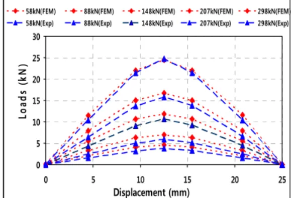
58kN(FEM) 88kN(FEM) 148kN(FEM) 207kN(FEM) 298kN(FEM) 58kN(Exp) 88kN(Exp) 148kN(Exp) 207kN(Exp) 298kN(Exp)
Fig. 8 Comparison of experimental and numerical displacements
0 50 100 150 200 250 300 350
0 5 10 15 20 25 30
Displacement(mm)
Load (kN)
FEM_nonlinear EXP
Fig. 9 Comparison of displacements at middle point
0 5 10 15 20 25 30 35 40
DT-1 DT-2 DT-3 DT-4 DT-5
No. of measured points
K(N/m)×106
K1 kN K2 kN K3 kN K4 kN K5 kN
Fig. 10 Experimental stiffness at measured points
were simulated from the FE model considering the same location of displacement transducers in the experimental test. Fig. 8 shows the comparison between the experimental and numerical displacements.
It can be observed from Fig. 9 that the displacement of the real structure is in close agreement with the one calculated from the finite element analysis. The nonlinearity of CFTA girder increases as the load step increases.
Fig. 10 shows the stiffness reduction at each
measured point with the increasing load step and the nonlinearity of structure. Fig. 11 shows stiffness difference at measured points of the experimental model, from which one can note that the girder is asymmetric and the right side of girder is weaker than the left side. Fig. 12 shows experimental results of the total stiffness of all load steps at each measured points. It demonstrates that it is possible to detect the voids inside CFTA girder by using Eq.
(2).
6. Conclusions
In this paper, a method for detection of manu- facturing defects in the CFTA girder is presented using static loading. An FE model has been pre- sented in order to simulate the behavior of the structure and to be used in the future for the design of similar structures. The FE model was utilized to verify the proposed method for manufacturing detection in this study. The stiffness at each
measured point is calculated in order to localize the voids inside the girder and to verify the integrity of the structure after construction. Both the numerical analysis and the experimental study showed that the proposed method can detect the voids inside the CFTA girder during the construction in the factory effectively. The proposed method seems to have potentials in detection of manufacturing defects of CFTA girders in case of mass production of the standard type in the factory, where the data of the intact model can be used for comparison of results and for identifying the manufacturing defects by using static loading.
Acknowledgement
This research is being funded by Korea Ministry of Land, Transport and Maritime Affairs (MLTM) through Korea Institute of Construction Technology (KICT). The authors wish to express their gratitude for the financial support.
References
Ahmad, S.H., Shah, S.P. (1982) Complete Triaxial Stress-Strain Curves for Concrete, J. Struct. Div., ASCE, 108, pp.728~742.
Charles, R.W., Cameron, B., Brown, C.B. (1999) Composite Action in Concrete Filled Tubes, Journal of Structural Engineering, ASCE, 25(5), pp.477
~484.
Chaudhary, S., Pendharkar, U., Nagpal, A.K.
(2007) A Hybrid Procedure for Cracking, Creep, Shrinkage and Thermal Gradient in Continuous Composite Bridges, Latin American Journal of Solids and Structures, 4(3), pp.203~227.
Chaudhary, S., Pendharkar, U., Nagpal, A.K.
(2009) Control of Creep and Shrinkage Effects in Steel Concrete Composite Bridges with Precast Decks, Journal of Bridge Engineering, ASCE, 14(5), pp.336~345.
Choi, E.S., Kim, M.C. (2008) A New Steel Jacketing Method for Concrete Cylinders and Comparison of the Results with a Constitutive Model, International Journal of Railway, 2008, 1(2), pp.72~81.
Chou C.C., Hsu C.P. (2008) Hysteretic Model Development and Seismic Response of Unbounded Post-Tensioned Precast CFT Segmental Bridge Columns, Earthquake Engineering and Structural Dynamics, 2008, 37, pp.919~934.
Elchalakani, M., Zhao, X.L., Grzebieta, R.H.
(2001) Concrete-Filled Circular Steel Tubes Subjected to Pure Bending, Journal of Constructional Steel Research, 57, pp.1141~1168.
Giannopoulos, G., Vantomme, J., Wastiels, J., Taerwe, L. (2003) Numerical Analysis and Experimental Validation for Static Loads of a Composite Bridge Structure, Journal of Composite Structures, 62, pp.235~243.
Huang, C.S., Yeh, Y.K., Liu, G.Y., Hu, H.T., Tsai, K.C., Weng, Y.T., Wang, S.H., Wu, M.H. (2002) Axial Load Behavior of Stiffened Concrete-Filled Steel Columns, Journal of Structural Engineering, ASCE, 128, pp.1222~1230.
Jeong, M.C., Yi, S.A., Kong, J.S. (2009) Linear Behavior Analysis and Stability Assessment of CFTA Girder, 2009 Conference of Computational Structural Engineering Institute of Korea.
Kosteski, N., Packer, J.A., Puthli, R.S. (2003) A Finite Element Method Based Yield Load Determination Procedure for Hollow Structural Section Connections, Journal of Constructional Steel Research, 59(4), pp.453~471.
Lee, H., Park, K.H., Kong, J.S. (2008) Analysis of Static Behavior of CFTA Girder, The Fourth International Conference on Bridge Maintenance, Safety and Management (IABMAS'08), Seoul, Korea, July 13~17.
Lu, H., Han, L.H., Zhao, X.L. (2009) Analytical Behavior of Circular Concrete-Filled Thin-Walled Steel Tubes Subjected to Bending, Thin-Walled Structures, 47, pp.346~358.
Nakamura, Sh.I., Momiyama, Y., Hosaka, T., Homma, K. (2002) New Technologies of Steel/
Concrete Composite Bridge, Journal of Constructional Steel Research, 58, pp.99~130.
Nakamura, Sh.I., Tanaka, H., Kato, K. (2008) Static Analysis of Cable-Stayed Bridge with CFT Arch Ribs, Journal of Constructional Steel Research, 65, pp.776~783.
Roh, H., Hong, S., Lee, S., Park, K., Lee, J.S.
(2009) Dynamic Amplification Factor of Concrete-
Filled Tubular Arch (CFTA) Girder due to the Effects of Moving Vehicles and PT Tendons, 2011 Conference of Computational Structural Engineering Institute of Korea.
Trung, T.T., Kim, J.H., Park, K.H., Kong, J.S.
(2008) Dynamic Behavior and Reliability Assessment of a CFTA girder subjected to Truck Collision, International Journal of Steel Structures, 8(4), pp.315~324.
Varma, A.H., Ricles, J.M., Sause R., Lu, L.W.
(2002) Experimental Behavior of High Strength
Square Concrete-Filled Steel Tube Beam-Columns, Journal of Structural Engineering, ASCE, 1285(3), pp.309~418.
논문접수일 2011년 10월 20일 논문심사일 2011년 11월 8일 게재확정일 2011년 11월 29일