Vol. 21, No. 1 (2011)
39
†Corresponding author
E-Mail : [email protected] (J. -H. Lee)
Analysis of the Aluminum Extrusion Process Equipped with the Continuous Heat Treatment System
Bong-Sang Lee, Young-Hee Cho, Jeong-Min Lee*, Hak-Jin Lim*, Jar-Myung Koo**, Bo-Hee Yoon***, Tae-Hyuk Lee*** and Jong-Hyeon Lee***
†Technical Research Laboratory, Dongyang AK Korea Co. Ltd., 404-20 Nojang-ri, Jeondong-myeon, Yeongi-gun, Chungnam 339-841, Korea
*Technical Research Laboratory, Poongsan Corporation, 2222-2 Sandae-ri, Angang-oup, Kyungju, Kyungbuk 780-775, Korea
**Division of Advanced Materials Engineering, Kongju National University, 182 Singwan-dong, Gongju-si, Chungnam 314-701, Korea
***Department of Nano Materials Engineering/Graduate School of Green Energy Technology, Chungnam National University, 79 Daehak-ro, Yuseong-gu, Daejeon 305-764, Korea
(Received November 4, 2010 : Received in revised form November 29, 2010 : Accepted November 30, 2010)
Abstract
In this study, the heat flow of the plant scale aluminum extrusion process was investigated to establish optimum continuous heat treatment conditions. During the extrusion of 6061 aluminum alloy, processing parameters such as the extrusion pressure, speed and temperature histories of billets were logged as a function of time. The surface temperature of the billets increased at constant ram speed, while it decreased with decreases of the ram speed. In order to maintain the billet temperature within a solutionizing temperature range prior to the succeeding water quenching step, the ram speed or the temperature of the blower should be controlled. The temperature histories of the billets during the extrusion and hot air blowing processes were successfully simulated by using the velocity boundary model in ANSYS CFX. The methodology to design an optimum process by using a commercial simulation program is described in this study on the basis of the metallurgical validation results of the microstructural observation of the extrudates. The developed model allowed the advantages of taking into account the motion of the extrudate coupled with the temperature change based on empirical data. Calculations were made for the extrudate passing through the isothermal chamber maintained at appropriate temperature. It was confirmed that the continuous heat treatment system is beneficial to the productivity enhancement of the commercial aluminum extrusion industry.Key words
aluminum, continuous heat treatment, simulation.1. Introduction
In the aluminum industry, the numerical analysis method has become a powerful tool to design a forming process.
Lou et al. reported that this method could cover from fundamental analysis on the metal flow of simple geometry to a complex profile
1)and Jo verified theoretical formulas for extrusion forces with an extrusion experiment.
2)Fang et al. also showed that preliminary analysis on the extrusion process could significantly minimize trial-and-errors con- fronting practices in their previous researches.
3)Hence, the main research direction of extrusion process is to attain a high productivity with a superior quality. The most popular numerical method used for simulating the aluminum alloy extrusion process is the finite element method, by which the metal flow and stress distributions are predicted. A good
example of a process that enhances productivity is the multi- hole extrusion process, which is usually applied to produce seamed hollow section tubes using porthole die. The multi- hole extrusion processes were also successfully investigated by Fang et al. using this finite element analysis.
4)Sequeire et al. successfully demonstrated that another
approach to enhance productivity of the extrusion process
is to combine a heat treatment procedure with the extrusion
step, where an extrudate drawn from the die directly goes
into a water bath.
5)In this step, the temperature of the
extrudate should be kept within the solutionizing tempera-
ture, because the aluminum alloys are supposed to be of a
solid solution prior to water quenching as experimentally
proved by Karabay et al.
6)However, the aluminum extrudate
tends to be rapidly cooled down after withdrawal from the
die as calculated by Parvizian et al.
7), and moreover, there is
always retention time for recharging a billet. And also,
over heat of the billet to maintain the solutionizing tem-
perature may cause the surface tearing.
8)reported yet. Hence, in this paper, we are going to report how the production scale continuous heat treatment system affected the product quality and how we made efforts to secure optimum processing parameters by using numerical analysis on the isothermal chamber temperature.
2. Experimental Procedure 2.1 Extrusion of aluminum alloys
Commercial Al 6061 alloy was used to prepare extrusion samples, and the chemical compositions are listed in Table 1. The extruder and its schematic diagram are presented in Fig. 1(a) and 1(b), respectively. The maximum pressure of the extruder is 4000 tons and a temperature of an extrudate is maintained at a predefined value by the isothermal chamber and then it is subsequently quenched. Variations of billet length, extrusion pressure and ram speed were monitored by data logging system simultaneously. The ini- tial temperatures of the billet, container and die were set to 761 K, 689 K and 733 K respectively. The temperature of an extrudate withdrawn out of the die was measured by K- type contact thermocouples on the surface of the extrudate before entering a heating furnace as shown in Fig. 2. The initial diameter of the billet was 330.2 mm and the diam- eters of die considered in this study were 100 mm, which is equivalent to R = 3.3. It is denoted by R and is given by the expression:
R = A
o/A
f(1)
In this equation, R is the extrusion ratio defined as the ratio of the initial billet cross-sectional area ( A
0) to the final cross-sectional area ( A
f).
The cross-sectional microstructure of the extrudate was investigated after extrusion according to processing param- eters.
2.2. Numerical analysis of temperature increase during extrusion process
The temperature increase of billet during extrusion was
simulated by using the coupled transient heat analysis method in CFX. Fig. 3 shows the initial mesh of an extrudate with inflated elements at the surface, and its initial and boundary conditions. Movement of the extrudate after extrusion process of aluminum was assumed by the linear translation of solid domain in a fluid. Hence the moving boundary condition was employed to implement the moving contact between the extrudate and the sur- rounding hot air. Table 2 shows the material properties and boundary conditions used for the simulation. In order to simulate the temperature increase of Al billet during
Table 1. Chemical composition of Al 6061 alloy in wt %.Components Al Cu Si Mg Zn Mn Cr Fe Ti
Composition Bal 0.15~0.4 0.4~0.8 0.8~1.2 0.25 0.15 0.04~0.35 0.7 0.15
Fig. 1. Photograph of 4000 ton extruder (a) and schematic diagram (b) of extruder equipped with the continuous heat treatment system.
Fig. 2. Temperature measurement point before entering the heating furnace.
extrusion operation, the tendency of the temperature profile was measured experimentally at the temperature measuring point as shown in Fig. 2 and the constants were extracted by the regression analysis using exponential function. Con- sequently, the surrounding air temperature of the billet surface can be described by functions of time and location along the z axis as described in equation (2) because the billet temperature gradually increases with extrusion pro- ceeds.
T
surround= ((exp( −B × z
2)) × 13)[K] + A × exp(−t/t
1)[K] + y
1(2) In the equation above, B, A, t
1and y
1are constants for describing the surrounding temperature change, which was obtained by regression of the experimental billet tem- perature change and z is length of the z axis. A variable temperature boundary condition with 150 W/m
2K of heat transfer coefficient was applied as a wall boundary con- dition by using CCL (CFX Command Language). The individual values are depicted in Table 2.
3. Results and Discussion
The main purpose of the press-quenching step is to attain a solution treatment effect with a single extrusion
operation without the reheating of a billet. Hence, the billet temperature should be maintained at a temperature not less than 803 K, which is the solutionizing temperature of Al6061 alloy. During a typical extrusion operation, the
Table 2. Material properties and boundary conditions for calculation.Property Value
Thermal conductivity (W/mK)
Al 6061 167
Air 0.0261
Density (kg/m3) Al 6061 2700
Air 1.185
Specific heat capacity (J/kgK)
Al 6061 896
Air 1000
Boundary condition constant of equation (2)
B, mm2 0.0001
A -38.17913
t1, s 36.48469
y1, K 340, 440, 800, 900, 950 Fig. 3. Mesh of Al 6061 billet and calculation conditions.
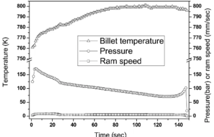
Fig. 4. Billet temperature, pressure and ram speed variations of Al 6061 extrusion process before press quenching.
Fig. 5. Calculated temperature contour of the billet cross section at 50 seconds after the extrusion onset according to the isothermal chamber temperature (initial billet temperature: 761 K). a) 340 K, b) 440 K, c) 800 K and d) 950 K.
billet temperature generally increases due to the internal plastic deformation energy and friction energy between the billet and die. Fig. 4 shows the measured temperature change of the billet with initial billet temperatures of 761 K at the billet surface before press quenching. It is clearly seen that at the beginning of extrusion, the extrusion pressure quickly reaches a peak and then decreases with extrusion time. This occurs because the resistance between the billet and die in the container decreases. At the end of the extrusion process, the extrusion pressure begins to rise again. This result agrees with former experimental and calculation results of Zhou et al., in which high pressure is needed due to the formation of radial metal flow toward the die aperture.
9)The billet temperature also gradually increases as extrusion proceeds due to heat generation as expected. However, it should be noted that the billet surface temperature is slightly below the solutionizing temperature of Al 6061. When the billet goes to the press quenching bath without the isothermal chamber, solu- tionizing would not be sufficient. As can be observed, after the pressure drop, the temperature of the billet enters the steady-state stage. This happens 70 seconds after the onset of extrusion, with a gradual decrease of pressure due to
reducing billet length in the container. It is a challenge to control the chamber temperature within the proper tem- perature range, even though the isothermal chamber was installed to keep the temperature of an extrudate above the solutionizing temperature through the extrusion process.
Excess heating of the chamber may cause grain growth or
distortion of the extrudate, especially at the end of the
extrusion process, while the solutionizing effect would not
be expected with low heating temperature. Hence, it is
important to visualize the temperature distribution of the
extrudate, in order to secure proper press quenching par-
ameters including an isothermal chamber temperature. For
this, a numerical analysis was performed with the geometry,
boundary and initial conditions as shown in Fig. 3. This
model allowed the advantages of taking into account the
motion of an extrudate coupled with temperature change
based on empirical data. Calculations were made on the
part of the extrudate passing through the isothermal cham-
ber maintained at appropriate temperature. An initial billet
temperature of 761 K was selected, which is generally used
in practice for Al 6061 billet. The temperatures of the
container and die were selected to be 72 K and 28 K lower
than the initial billet temperature to allow the heat generated
Fig. 6. Calculated temperature distribution along the billet center line according to isothermal chamber temperature (initial billet temperature : 761 K). a) 340 K, b) 440 K, c) 800 K and d) 950 K.to dissipate, as a measure to prevent heat shortage from occurring as the process approached its end.
The calculated temperature contours of the billet cross sections are presented in Fig. 5 as a function of the isothermal chamber temperature with initial billet tempera-
ture of 761 K. In the case of 340 K as the isothermal
chamber temperature, the extrudate temperature decreases
immediately after leaving the die exit. With this condition,
the temperature of the extrudate prior to entering quenching
bath is between 510 K and 525 K at the surface and the
Fig. 7. Cross-sectional microstructure of Al 6061 sampled in the middle of the extrudate (80 seconds after the onset of extrusion) after press quenching according to the temperature of the isothermal chamber. a),b) 340 K, c),d) 440 K, e),f) 540 K and g),h) 800 K.center respectively. The general tendency of the tempera- ture distribution is identical when the isothermal chamber temperature increased to 440 K as shown in Fig. 5(b). This is due to heat loss to the relatively cold environments that are 340 K and 440 K lower than the billet temperature. The
temperature distribution becomes completely changed as the isothermal chamber temperature increased to 800 K, which is a higher temperature than the initial billet temperature.
The highest temperature is visible at the bottom place,
where the extrudate enters into the quench bath, and the
Fig. 8. Cross-sectional microstructure of Al 6061 sampled at the end of the extrudate (120 seconds after the onset of extrusion) after press quenching according to the temperature of the isothermal chamber. a),b) 340 K, c),d) 440 K, e),f) 540 K and g),h) 800 K.minimum temperature was recorded as 786 K as shown in Fig. 5(c). Such temperature range is acceptable for press quenching, when considering solutionizing temperatures of Al 6061, while a higher isothermal chamber tempera- ture, Fig. 5(d), would lead to deteriorative effects on the characteristics of an extrudate, such as grain growth and buckling.
In order to comprehensively observe the temperature distributions of the extrudates at centerline, temperature histories were reconstructed as functions of distance from the die exit and extrusion time as shown in Fig. 6. With the 340 K as the isothermal chamber temperature, see Fig.
6(a), the temperature of the part of the billet decreases below the initial billet temperature at the early stage of the extrusion step due to rapid cooling. The gradual increase of the billet temperature with time is attributed to the internal heat generation caused by friction heat and deformation energy, which is consistent with the results from Saha.
10)In the case of 440 K as the chamber temperature, the minimum temperature never falls down below the initial billet temperature. In this scenario, the uniform solu- tionizing temperature of 803 K leached 100 seconds after the onset of extrusion and then the billet temperature ranges between 810 and 817 K at the end of extrusion as shown in Fig. 6(b). This means that a proper press quenching con- dition in terms of billet temperature is only attainable after 100 seconds of extrusion. In other words, significant amounts of the extrudate may be off specification at 440 K as the isothermal chamber temperature. When the chamber temperature increases to 800 K, the solutionizing tempera- ture could be achieved 48 seconds after extrusion, and the time decreased to 40 seconds with 950 K as the chamber temperature as shown in Fig. 6(c) and d. From the calcula- tion results, with proper programming of the isothermal chamber temperature, the extrudate can be managed within appropriate temperature schemes. However, the early part of the extrudate is always out of control, no matter how precisely the chamber temperature is controlled, because the traveling distance of the extrudate is too short to allow the heating up to the desired temperature range in the chamber.
Fig. 7 shows the representative cross-sectional microstruc- ture of Al 6061 sampled in the middle of the extrudate after press quenching according to the temperature of the isothermal chamber. It clearly shows an equiaxied micro- structure without a flow line because the sampling plane is perpendicular to the extrusion direction. There are no sig- nificant differences among the samples except for surface parts which have a somewhat larger grain size probably due to a higher temperature. For the comparison between the microstructures at a different extrusion stage, a series of samples were taken from the end of the extrudates
according to the isothermal chamber as shown in Fig. 8.
The cross-sectional microstructures completely changed into elongated grains. These results agree with the experi- mental observation in Fig. 4 that high pressure is needed at the end of the extrusion stage due to the formation of a radial metal flow toward the die aperture. The present results would be useful to predict temperature profiles of the extrudates traveling through the press quenching device in the extrusion industry.
4. Conclusion
In the aluminum extrusion practice, the press-quenching process is frequently applied for solution treatable alloys to enhance productivity by removing the reheating step.
To accurately predict the extrudate temperature prior to the quenching step, a very detailed model is necessary. A numerical model of moving the boundary for the extrusion of Al 6061 billet shows that there are uncontrollable regions in the extrudates, in terms of temperature management prior to the press-quenching step. It was discovered, however, that most of the extrudate temperature is able to be con- trolled by using the proper isothermal chamber temperature.
The present results would be useful background for setting up the press-quenching process in the aluminum extrusion industry.
Acknowledgments
This study was financially supported by the research fund of Chungnam National University, South Korea, in 2009.
References
1. S. Lou, G. Zhao, R. Wang and X. Wu, J. Mater. Process.
Tech., 206(1-3), 481 (2008).
2. H. H. Jo, Kor, J. Mater. Res., 4(8), 945 (1994) (in Korean).
3. G. Fang, J. Zhou and J. Duszczyk, J. Mater. Process. Tech., 199(1-3), 91 (2008).
4. G. Fang, J. Zhou and J. Duszczyk, J. Mater. Process. Tech., 209(4), 1891 (2009).
5. S. S. Tavares and S. Sgobba, J. Mater. Process. Tech., 143- 144, 584 (2003).
6. S. Karabay, M. Yilmaz and M. Zeren, J. Mater. Process.
Tech., 160(2), 138 (2005).
7. F. Parvizian, T. Kayser, C. Hortig and B. Svendsen, J.
Mater. Process. Tech., 209(2), 876 (2009).
8. H. S. Kim, Kor, J. Mater. Res., 16(2), 137 (2006) (in Korean).
9. J. Zhou, L. Li and J. Duszczyk, J. Mater. Process. Tech., 134(3), 383 (2003).
10. P. K. Saha, Wear, 218(2), 179 (1998).