논문 2014-51-3-15
Simplified DC Calculation Method for Simplified Depth Coding Mode of 3D High Efficiency Video Coding
Hyunho Jo
*, Jin Young Lee
**, Byeongdoo Choi
**, and Donggyu Sim
*ⓒ*
*Abstract
This paper proposes a simplified DC calculation method for simplified depth coding (SDC) mode of 3D High Efficiency Video Coding (3D-HEVC) to reduce the computational complexity. For the computational complexity reduction, the current reference software of 3D-HEVC employs reference samples sub-sampling method. However, accumulation, branch, and division operations are still utilized and these operations increase computational complexity. The proposed method calculates DC value without those operations. The experimental results show that the proposed method achieves 0.1% coding gain for synthesized views in common test condition (CTC) with the significantly reduced number of computing operations.
Keywords: 3D-HEVC, SDC, HEVC
Ⅰ. Introduction
High Efficiency Video Coding (HEVC) is the state-of-the-art video compression technology that was released as an international standard in January 2013 with collaboration of ITU-T Video Coding Expert Group (VCEG) and ISO/IEC Moving Picture Expert Group (MPEG). HEVC shows about 50%
bit-rate reduction, compared to H.264/AVC High Profile in subjective quality. HEVC is expected to replace H.264/AVC for various media applications because it has significantly higher compression performance than H.264/AVC
[1~2].
MPEG and VCEG also organized Joint Collaborative Team on 3D Video Coding Extension
* Dept. of Computer Engineering, Kwangwoon University
** Samsung Electronics Co., Ltd.
ⓒ Corresponding Author(E-mail: [email protected])
※ This work was partially supported by the National Research Foundation of Korea (NRF) grant funded by the Korean Government (NRF-2010-0025325) and partly supported by Samsung Electronics.
접수일자: 2013년8월20일, 수정완료일: 2014년3월5일
Development (JCT-3V) to develop 3D video technology more advanced than Multiview Video Coding (MVC) as an amendment of H.264/AVC.
JCT-3V are developing two additional standards that
are H.264/AVC-based and HEVC-based ones
according to a codec for the base-view. 3D-AVC is
the amendment based on H.264/AVC, MV-HEVC is
one based on HEVC. In addition, 3D-HEVC is also
the amendment based on HEVC with depth map
coding. For the coding of depth maps, various new
coding tools are employed in 3D-HEVC. Among
those new coding tools, a simplified depth coding
(SDC) is an alternative intra coding mode without
transform and quantization with consideration of the
characteristic of depth maps. The current reference
software of 3D-HEVC employs sub sampling-based
DC calculation method for SDC mode to reduce the
computational complexity
[3]. However, accumulation
with varying number of samples, branch, and division
operations are still utilized and these operations
increase computational complexity in encoder and
decoder sides. In this paper, we proposes a simplified
DC calculation method for segments without the
accumulation, branch, and division operations.
This paper is organized as follows. Section Ⅱ presents the simplified depth coding mode in 3D-HEVC. In Section Ⅲ, the proposed simplified DC calculation method for SDC coding mode is proposed.
Section Ⅳ shows performance evaluation of the proposed method and Section Ⅴ concludes the presented work with further research topics.
Ⅱ. Simplified depth coding of 3D-HEVC
The input of 3D-HEVC is a small number of captured views and associated depth maps. By encoding the associated depth maps, a decoder can synthesize additional arbitrary viewpoints using depth-image-based rendering (DIBR) techniques
[4]. That is called as multiview video plus depth (MVD) format. Using the MVD format for 3D video is a quite effective way from the coding efficiency point of view since encoders transmit a small number of views with associated depth maps. Various technologies have been proposed during standardization phase for depth map coding. For the intra prediction, depth modeling mode (DMM) and SDC are the principal coding tools.
2.1. Intra coding modes of 3D-HEVC
HEVC version 1 employs 35 prediction modes for intra prediction that consist of Planar, DC, and 33 angular prediction modes. DMM and SDC coding modes are additionally included in the intra coding modes for depth maps
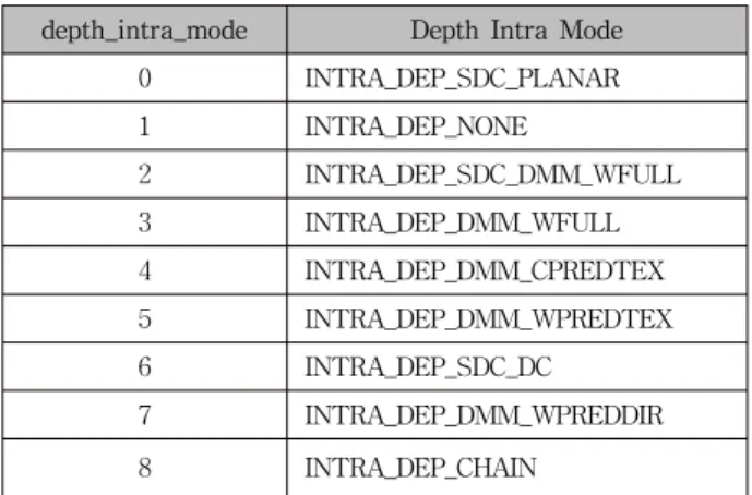
[4]. Table 1 shows the specification of “depth_intra_mode” syntax element (SE) and associate names of 3D-HEVC. Note that
“INTRA_DEP_NONE” means that conventional intra prediction modes of HEVC version 1.
In general, depth maps can be partitioned into two segments on edges at the object boundaries and the samples in each segment are nearly constant or slowly varying sample values. DMM coding modes provide an effective way to divide the prediction unit
depth_intra_mode Depth Intra Mode
0 INTRA_DEP_SDC_PLANAR
1 INTRA_DEP_NONE
2 INTRA_DEP_SDC_DMM_WFULL
3 INTRA_DEP_DMM_WFULL
4 INTRA_DEP_DMM_CPREDTEX
5 INTRA_DEP_DMM_WPREDTEX
6 INTRA_DEP_SDC_DC
7 INTRA_DEP_DMM_WPREDDIR
8 INTRA_DEP_CHAIN
Table 1. Specification of depth_intra_mode and associated names.
(PU) into two non-rectangular regions. The residual signals is coded after transform and quantization as conventional intra prediction modes.
2.2. Simplified depth coding mode
SDC is an alternative coding mode for depth maps like as DMM
[5]. SDC coding mode consists of three intra prediction mode such as DC, Planar, and DMM Mode-1 as shown in Table 1. A coding block (CB) will be represented with one segment in the case of DC or Planar prediction modes and with two segments in the case of DMM Mode-1 prediction mode. At the encoder side, the SDC module calculates the mean of the original depth value (d
orig) and the predicting depth value (d
pred) that is made by intra prediction with DC, Planar, or DMM Mode-1. A depth lookup table (DLT) is utilized to map the d
origand d
predto index values. The difference of two indexes to be transmitted to the decoder is given by
) ( )
(
orig predresi
I d I d
i = − (1)
where I(·) denotes the DLT. Consequently, residual
values can be coded by signalling only the difference of
indexes of the DLT, which reduces the bits for residual
signals. Note that transform and quantization are not
utilized for the SDC mode. The mean of the predicting
depth value is calculated by Eq. (2).
Fig. 1. 2:1 sub-sampling for the reference samples.
N sum mean
samples prediction
p p
sum N i
i i
/
) (
1
0
=
∈
= ∑
−=
(2)
where N is the number of pixels in a segment. The reference software of 3D-HEVC (HTM 7.0r1) employs partial samples in 32×32 or 64×64 predicted blocks by 2:1 sub-sampling method to decrease computational complexity in DC value calculation, as shown in Fig.
1
[3]. However, the process still uses accumulation operation with varying number of samples, branch, and division operations. These operations have high computation complexity and it is not appropriate to implement them with hardware logics.
Ⅲ. Proposed simplified DC calculation method
This paper proposes a simplified DC calculation method for the SDC coded block to obtain a DC value
[6]. The proposed method calculates DC value using the partial samples of the predicted block based
Fig. 2. Modified selection of a sample for simplified DC calculation for SDC (DC mode).
(a) Case 1 (b) Case 2
(c) Case 3 (d) Case 4
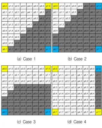
Fig. 3. Modified selection of a sample for simplified DC calculation for SDC (DMM Mode-1).
on the characteristics of three types of prediction modes (DC, Planar, and DMM Mode-1) of SDC coded block.
For DC prediction mode, the conventional method calculates mean value of a segment by using Eq. (2).
However, the proposed method uses the right-bottom sample as a DC value, as shown in Fig. 2. Note that inner boundary filtering is utilized for 4×4, 8×8, and 16×16 blocks for the DC prediction mode. However, the right-bottom sample is the same to the dominant sample in a block, regardless of inner boundary filtering.
For DMM Mode-1 prediction mode, the left-top, right-top, left-bottom, and right-bottom samples in a predicted block are used to find the DC values of segment-1 and segment-2, as shown in Fig. 3.
Figure 3 shows various segment patterns of DMM Mode-1. The proposed method uses a DC value for each segment, regardless of segment patterns.
Conventional method calculate DC value for each
segment, as follows:
2 2 2
1 0 2
1 1 1
1 0 1
/
) 2 (
/
) 1 (
2 1
N sum mean
segment p
p sum
N sum mean
segment p
p sum
j N
j j
i N
i i
=
−
∈
=
=
−
∈
=
∑
∑
−
=
−
=
(3)
where N
1and N
2are the number of pixels in segment-1 and segment-2, respectively. As the DMM Mode-1 uses a constant predictor for each segment, all samples in a segment are the same. Therefore, the proposed method checks four corners samples to determine a DC value without accumulation and division operations.
For Planar prediction mode, the conventional method calculates mean value of a segment by using Eq. (2) that uses accumulation and division operation.
However, the proposed method employs the left-top, right-top, left-bottom, and right-bottom samples in a predicted block to obtain the DC value, as show in Fig. 4. The average value to determine the DC value is calculated by follows:
2 2 >>
+ +
+ +
=(p − p − p − p − )
mean lefttop righttop leftbottom rightbottom
(4)
Fig. 4. Modified selection of a sample for simplified DC calculation for SDC (Planar mode).
Ⅳ. Experiment results
To evaluate computational complexity of the proposed algorithm, the number of pixels involved in
Prediction Mode
Block Size
Number of pixels
involved Ratio
HTM 7.0r1 Proposed
DC
8x8 64 1 1.56%
16x16 256 1 0.39%
32x32 256 1 0.39%
64x64 1024 1 0.10%
Planar
8x8 64 4 6.25%
16x16 256 4 1.56%
32x32 256 4 1.56%
64x64 1024 4 0.39%
DMM Mode-1
8x8 64 4 6.25%
16x16 256 4 1.56%
32x32 256 4 1.56%
64x64 n/a n/a n/a
Table 2. Comparison of number of pixels involved for DC calculation.
Prediction Mode
Block Size
Operation types and number of that operations
HTM 7.0r1 Proposed
Addition Division Branch Addition Shift Branch
DC
8x8 126 1 64 - - -
16x16 510 1 256 - - -
32x32 510 1 256 - - -
64x64 2046 1 1024 - - -
Planar
8x8 126 1 64 4 1 -
16x16 510 1 256 4 1 -
32x32 510 1 256 4 1 -
64x64 2046 1 1024 4 1 -
DMM Mode-1
8x8 126 2 64 - - -
16x16 510 2 256 - - -
32x32 510 2 256 - - -
64x64 n/a n/a n/a n/a n/a n/a
Table 3. Comparison of involved operation types and number of operations.
HTM 7.0r1 and proposed method is compared.
Furthermore, the types of operations and number of those operations for the proposed method and HTM 7.0r1 are also compared. As show in Table 2, the proposed method employs about 1.9% of pixels, compared to the HTM 7.0r1. It means that the proposed method significantly reduced the number of pixels to be used for DC calculation.
As shown in Table 3, the proposed method does not employ any computational operations to calculate DC value in the case of DC and DMM Mode-1 mode.
For the Planar mode, the proposed method uses 4 addition and 1 shift operations. Note that HTM 7.0r1 uses division operator to calculate a DC value for each segment.
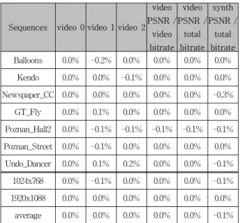
For the evaluation of coding efficiency, the
proposed method is implemented on top of HTM
7.0r1, and it is compared with HTM 7.0r1 under the
common test condition (CTC)
[7]. Table 4 shows BD
rate results for 3-view case under CTC. Since the
Sequences video 0 video 1 video 2 video PSNR /
video bitrate
video PSNR /
total bitrate
synth PSNR /
total bitrate Balloons 0.0% -0.2% 0.0% 0.0% 0.0% 0.0%
Kendo 0.0% 0.0% -0.1% 0.0% 0.0% 0.0%
Newspaper_CC 0.0% 0.0% 0.0% 0.0% 0.0% -0.3%
GT_Fly 0.0% 0.1% 0.0% 0.0% 0.0% 0.0%
Poznan_Hall2 0.0% -0.1% -0.1% -0.1% -0.1% -0.1%
Poznan_Street 0.0% -0.1% 0.0% 0.0% 0.0% 0.0%
Undo_Dancer 0.0% 0.1% 0.2% 0.0% 0.0% -0.1%
1024x768 0.0% -0.1% 0.0% 0.0% 0.0% -0.1%
1920x1088 0.0% 0.0% 0.0% 0.0% 0.0% 0.0%
average 0.0% 0.0% 0.0% 0.0% 0.0% -0.1%