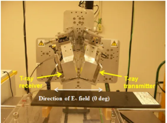
Fig 1. Schematic of the experimental setup used for terahertz transmission imaging
Characterization of Fiber Direction Influence in CFRP Composites Using Advanced NDE Techniques
Kwang-Hee Im
1,#, Ju-Hwan Jang
1, Chong-Gui Back
1, Ok-Su Jeong
1,
andDavid K. Hsu
21 Department of Automotive Eng., WoosukUniversity 490, Hujung-ri, Samrae-up, Wanju-kun, Chonbuk, 565-701, Korea 2 Center for Nondestructive Evaluation, Iowa State University,IA 50011, USA
# Corresponding Author / E-mail: [email protected], TEL: +82+63-290-1473, FAX: +82+63-291-9312 (Manuscript received: Sep, 16, 2012 / Revised: Nov, 15, 2012 / Accepted: Nov, 27, 2012)
A nondestructive technique would be very useful. Advanced NDE T-ray (terahertz ray) techniques of technology and instrumentation has provided a probing field on the electromagnetic spectrum. However, the T-ray is limited in order to penetrate a conducting material to some degree. Here, the T-ray would not go through easily the CFRP composite laminates since carbon fibers are electrically conducting while the epoxy matrix is not. So, investigation of terahertz time domain spectroscopy (THz TDS) was made and reflection and transmission configurations were studied for a 48-ply thermoplastic PPS(poly-phenylene sulfide)-based CFRP solid laminate. It is found that the electrical conductivity of CFRP composites depends on the direction of unidirectional fibers.
KEYWORDS: CFRP composites, NDE, T-ray, C-scan image, Electrical conductivity
1. Introduction
Especially the importance of CF/Epoxy composites has been generally recognized
(1), and CFRP composite laminates are widely used. Also, composites are currently being considered for many structural (aerospace vehicles, automobiles, trains and ships) applications due to their potential for reducing structural weight. Increasingly more high performance engineering structures are being built with critical structural components made from composite materials. So, CF/Epoxys are a material class for which nondestructive material property characterization is as important as flaw detection. Increasingly, a new NDE terahertz radiation has been recognized for their importance in technological applications. Recently, T-ray (terahertz ray) advances of technology and instrumentation has provided a probing field on the electromagnetic spectrum. The terahertz radiation is of critical importance in the spectroscopy evaluation of airport security screening, medical imaging, polar liquids, industrial systems and composites as well
(2). Also the terahertz time domain spectroscopy (THz-TDS) is leading noncontact accurate detection of flaws and impact damages in composites, in which the THz-TDS is based on photoconductive switches, which rely on the production of few-cycle terahertz pulses using a femtosecond laser to excite a photoconductive antenna
(3~4). Another method is optical heterodyne conversion, or photomixing, which can be obtained using two continuous-wave (CW) lasers
(5). The mixing of two lasers could produce beating, which can modulate the conductance of a photoconductive switch by the terahertz difference frequency. So, the CW-terahertz (CW-THz) radiation is produced.
So, the chemical property of materials is of great interest and the study
presents many challenges. At the THz fundamental level, the problem
is one of describing the overall properties of CFRP composite
materials. In some cases, T-ray images can show chemical compositions
of the object. These features of T-ray imaging have generated interest
in commercial applications in diverse areas as moisture analysis,
quality control of plastic parts and packaging inspection (monitoring)
(6).
In this paper, we carried out our investigations of the index of
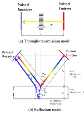
ICMTE(a) Through-transmission mode
(b) Reflection mode
Fig. 2 Measurement of refractive index for T-ray applications
Table 1 THz pulse reflected from PMMA, Fused quartz and GFRP composites
Materials Refractive index(n)*
Refractive index (n)
Through-transmission mode Reflection mode
PMMA 1.60±0.08 1.61±0.07 1.62±0.03
Fused quartz 1.95± 0.05 1.95±0.05 1.94±0.05
GFRP - 2.13±0.05 2.12±0.05
*Referred to Reference [8].