Vol. 25, No. 9 (2015)
455
Synthesis of Nanosized SnS-TiO
2Photocatalysts with Excellent Degradation Effect of TBA under Visible Light Irradiation
Ze-Da Meng 1,2 , Lei Zhu 2 , Kefayat Ullah 2 , Shu Ye 2 and Won-Chun Oh 2†
1Jiangsu Key Laboratory of Environmental Functional Materials, College of Chemistry and Bioengineering, Suzhou University of Science and Technology, Suzhou 215009, China
2Department of Advanced Materials Science & Engineering, Hanseo University, Seosan-si, Chungnam-do 356-706, Korea
(Received May 19, 2015 : Revised August 5, 2015 : Accepted August 6, 2015)
Abstract
SnS-TiO2 nanocomposites are synthesized using simple, cheap, and less toxic SnCl2 as the tin (II) precursor. The prepared nanoparticles are characterized using powder X-ray diffraction (XRD), transmission electron microscopy (TEM), and UV-Vis diffuse reflectance spectra (DRS). The XRD and TEM results indicate that the prepared product has SnS nanoparticles and a grain diameter of 30 nm. The DRS demonstrate that SnS-TiO2 possesses the absorption profile across the entire visible light region. The generation of reactive oxygen species is detected through the oxidation reaction from 1,5-diphenyl carbazide (DPCI) to 1,5-diphenyl carbazone (DPCO). It is found that the photocurrent density and photocatalytic effect increase with the modified SnS. Excellent catalytic degradation of Texbrite BA-L (TBA) solution is observed using the SnS-TiO2 composites under visible light irradiation. It is proposed that both the strong visible light absorption and the multiple exciton excitations contribute to the high visible light photocatalytic activity.Kye words
SnS, Texbrite BA-L (TBA), visible light, photosensitized, TEM.1. Introduction
The application of photocatalytic technology using semi- conductors to the solution of environmental problems has received much attention. Many studies have shown that heterogeneous photocatalysis through light illumination on a semiconductor surface is an attractive advanced oxidation processes.
1)Under irradiation, the semiconductor is excited to generate hole and electron pairs, and the holes subsequently react with adsorbed hydroxyl ions to generate hydroxyl radicals, while the electrons react with adsorbed oxygen to generate superoxide ions.
2)These oxidizing substances, which have higher reaction activity than common oxygen molecules, can completely destroy various organic pollutants in wastewaters.
3)However, only approximately 3-5 % of the solar spectrum falling on the semiconductor can be used, which means that the efficient utilization of solar energy by the semiconductor is limited.
4)Titanium dioxide (TiO
2) or zinc oxide (ZnO), as a photocatalyst irradiated by ultrasound to produce an
excited source of radicals, has been successfully used in the degradation of toxic organic compounds and dye pollutants. In order to enhance the photocatalyst degradation efficiency and to search for new highly active photo- catalysts, it is necessary to study new catalysts.
5)Several traditional strategies are employed to develop visible-light-driven photocatalysts, including (i) the doping of foreign elements into photocatalytic materials with a wide band gap, (ii) organic dye-sensitizing of photo- catalysts, extensively applied in a solar cell, and (iii) compositing with a semiconductor of a narrow band gap.
6)These strategies extend the absorption band into the visible-light region, and also promote the photocatalytic activity under visible-light in some cases.
7)Tin chalcogenides are attractive semiconductor materials and potentially used as solar cell, holographic recording medium, light-emitting diodes, electrical switching, lithium ion battery, gas-sensor and optical material
8)etc. Among them, SnS is one of important semiconductor material exhibiting both the p- and n-type conduction with a band
†
Corresponding author
E-Mail : [email protected] (W.-C. Oh, Hanseo Univ.)
© Materials Research Society of Korea, All rights reserved.
This is an Open-Access article distributed under the terms of the Creative Commons Attribution Non-Commercial License (http://creative-
commons.org/licenses/by-nc/3.0) which permits unrestricted non-commercial use, distribution, and reproduction in any medium, provided the
original work is properly cited.
gap between those of Si (1.12 eV) and GaAs (1.43 eV).
9)1,5-diphenyl carbazide (DPCI) can be oxidized by oxidizing substances into 1,5-diphenyl carbazone (DPCO), which can be extracted by organic solvents and display an obvious absorbance in a certain range of wavelength.
10,11)In this work, we report on the synthesis of SnS coupled with TiO
2, which combines the excellent charge transport property of the SnS. These catalysts were irradiated with visible light and their catalytic activities were compared.
The catalytic efficiency of the SnS-TiO
2composite was evaluated by measuring the photo degradation of Texbrite BA-L (TBA) and 1,5-diphenyl carbazide (DPCI).
2. Experimental 2.1 Materials
Benzene (99.5 %) and ethyl alcohol were purchased as reagent-grade from Duksan Pure Chemical Co. (Korea) and Daejung Chemical Co. (Korea), and used as received.
Titanium-(IV) n-butoxide (TNB, C
16H
36O
4Ti) as the titanium source for the preparation of the SnS/TiO
2composites was purchased as reagent-grade from Acros Organics (Morris Plains, NJ, USA). Tin (II) chloride (SnCl
2) and sodium sulfide·5-hydrate (Na
2S·5H
2O) were supplied by Duksan Pure Chemical Co., Ltd, Korea. Texbrite BA-L (TBA) was purchased from Texchem Co. Ltd, Korea.
1,5-diphenyl carbazide, 99.9 %, Duksan Pure Chemical Co., Ltd) was of analytical grade. All chemicals were used without further purification, and all experiments were carried out using distilled water.
2.2 Preparation of SnS
2particles
The SnS
2nanoparticles were prepared via a precipitation process using SnCl
2and Na
2S·5H
2O as precursors. First, 0.57 g of SnCl
2was dissolved in 100 mL of distilled water, and then 0.006 mol of Na
2S·5H
2O solution was added drop wise into the above solution with sonication at room temperature for 30 min. Then, the mixture was vigorously stirred and ultrasonication for 6 h. For purication, the mixture was rinsed and centrifuged several times with acetone and distilled water. After filtration and drying under vacuum at 80
oC, SnS was obtained as a black powder.
2.3 Preparation of SnS-TiO
2particles
A stoichiometric amount of 30 ml of SnCl
2solution was mixed with 2 ml TNB and 50 ml benzene solution.
With continuous stirring at 343 K, 50 ml of Na
2S aqueous solution was then added to the mixture drop by drop, respectively, at the rate of 6 drips/minute. After stirring for 7 h, the final mixture was then filtered and washed with deionized water. Through heat treatment at 573 K for 1 h, the SnS-TiO
2powder was obtained.
2.4 Characterization of SnS-TiO
2compounds For the measurement of structural variations, XRD patterns were taken using an X-ray generator (Shimadzu XD-D1, Japan) with Cu Ká radiation. SEM was used to observe the surface state and structure of SnS
2-TiO
2composites using a scanning electron microscope (JSM- 5200 JOEL, Japan). Energy dispersive X-ray (EDX) spectroscopy was also used for the elemental analysis of the samples. The Brunauer-Emmett-Teller (BET) surface area was determined by N
2adsorption measurements at 77 K (Monosorb, USA). Transmission electron microscopy (TEM, JEOL, JEM-2010, Japan) was used to observe the surface state and structure of the SnS-TiO
2composites.
At the acceleration voltage of 200 kV, TEM was used to investigate the size and distribution of the titanium and iron particles deposited on the CNT surfaces of various samples. TEM specimens were prepared by placing a few drops of the sample solution on a carbon grid.
2.5 Catalytic degradation of TBA
Photocatalytic activity was evaluated by dye degradation in aqueous media under visible-light irradiation. For visible-light irradiation, the reaction beaker was located axially and held in a visible lamp box (8 W, halogen lamp, KLD-08L/P/N, Korea). The luminous efficacy of the lamp was 80 lm/W, and the wavelength was 400 nm- 790 nm. The lamp was located at a distance of 100 mm from the aqueous solution in a dark box. The amount of photocatalytic composite used was 0.05 g/(50 ml solution).
On the other hand, 0.001 v/v aqueous solution of TBA was also prepared with deionized water in 1 L measuring flasks, respectively. The concentrations of the stocks solutions of the three dye solutions depended on various factors such as color intensity of the dyes, molecular structure complexity of the dyes, intensity of visible light falling on the solutions and activity of the photocatalysts.
The reactor was placed for two hours in the dark box to make the photocatalytic composite particles adsorb as many dye molecules as possible. After the adsorption phase, the visible-light irradiation was restarted to make the degradation reaction proceed. To perform dye degradation, a glass reactor (diameter = 4 cm, height = 6 cm) was used, and the reactor was placed on the magnetic churn dasher.
The suspension was then irradiated with visible light for
a set irradiation time. Visible-light irradiation of the reactor
was performed for 90 min. Samples were withdrawn
regularly from the reactor, and dispersed powders were
removed in a centrifuge. The clean transparent solution
was analyzed by a UV-vis spectrophotometer (Optizen
POP, Mecasys Co., Ltd., Korea). Visible light irradiation
of the reactor was done for 30 min, 60 min and 90 min,
respectively. Samples were withdrawn regularly from the
reactor and dispersed powders were removed by a
centrifuge. The clean transparent solution was analyzed by UV/vis spectroscopy.The dye concentration in the solution was determined as a function of the irradiation time.
2.6 Evaluation of reactive oxygen species
Firstly, six 10.00 mL DPCI stock solu-tions (1.00 × 10
−2mol/L) were added into three 80 mL volumetric flasks, respectively. And then 50 mg SnS-TiO
2photocatalysts were added to above DPCI solutions, and diluted to 50 mL with double distilled water. For all three solutions, the final DPCI concentration and SnS-TiO
2photocatalyst amount were 2.00 × 10
−3mol/L and 1.00 g/L, respectively.
Among them, the reactors were put into a visible light apparatus away from light directly under visible light irradiation. After 30 min, 60 min and 180 min irradiation, from each sample 10.00 mL solution was taken exactly and extracted with benzene, respectively. And then, all extracted solutions were diluted to 10.00 mL with benzene solution and their UV-vis spectra were determined.
3. Results and Discussion
3.1 Surface characteristics of the samples
The additional amount of TiO
2was found to be a key
factor that can affect the morphology and phase structure of tin sulphides through the phase-controlled process.
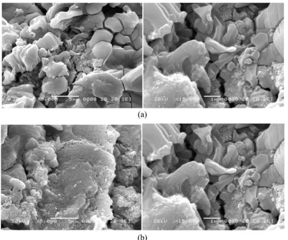
Fig. 1(a, b) shows the typical scanning electron microscope (SEM) images of the as-prepared samples. Without addition of TiO
2, SnS was synthesized showing a smaller sized flake-like shape (~2-3 μm in width, ~500 nm in thickness).
12)Fig. 1 a is the SEM image of prepared SnS.
Then, by adding TiO
2, flake-like shape of SnS was obtained with a uniform size (~100 nm in thickness). We conjecture that the flake-like shape particles in SnS-TiO
2composites are SnS particles on the surface of TiO
2clusters (Fig. 1b). By comparing Fig. 1(a) and (b), after added TiO
2, the dispersion of SnS has a little meliorate.
Fig. 2 shows HRTEM images of the SnS-TiO
2composites with different magnifications. HRTEM is a technique used for analyzing the morphology, crystallographic structure, and even the composition of a specimen. Fig. 2 gives direct evidence that the TiO
2are well contact with SnS. As shown in Fig. 2, particles were observed upon enlargement of the images. This indicates that the surfaces of the SnS particles are cleaned under exposure to the reaction conditions. SnS particles were uniform distributed on the surface of TiO
2. The size of SnS and TiO
2were approximately 45 nm.
Fig. 1. SEM images of composites: SnS (a), and SnS-TiO
2(b).
3.2 Structural features of the catalyst
XRD was used to determine the crystallographic struc- ture of the inorganic component of the composite. X-ray diffraction patterns reveal the polycrystalline nature of the particles with orthorhombic crystal structure. The comparison of the observed diffraction peak patterns with TiO
2nanoparticles and SnS-TiO
2nanocomposites was carried out. In Fig. 3, the main sharp peaks, which were assigned to (120), (021), (101), (040), (002), and (042) crystal planes, originate from the acanthite SnS phase.
13)The crystal structure of TiO
2is determined mainly by the heat treated temperature. The peaks at 25.3
o, 37.5
o, 48.0
o, 53.8
o, 54.9
o, and 62.5
o2 θ were assigned to the (101), (004), (200), (105), (211), and (204) planes of anatase.
14)From the XRD patterns (Fig. 3), it is also possible to compute the % crystallinity and crystallite size. The amorphous phase fraction of the sample may be deter- mined by taking the ratio of the amorphous area (area not under the peaks) of the X-ray diffractogram to the total area. Also the peaks at different crystal planes of SnS-TiO
2nanocomposite matches exactly with that of TiO
2indicating essentially no difference with respect to the type of crystalline phase in the two products. It is found that TiO
2shows more crystallinity than prepared SnS-TiO
2. nanocomposite. This is attributed to the adverse environments created when added SnS, not allowing the nucleation and crystal growth to occur fully.
15)The UV-vis absorption spectra of the samples are shown in Fig. 4. We find that TiO
2and SnS-TiO
2composites have great absorption in the ultraviolet and visible regions, which we can calculate that these composites have great photocatalytic activity under ultraviolet light and visible light irradiation. SnS has photocatalytic activity in the visible region due to SnS having a relatively small band gap. It is found that the present SnS nanoparticles have an absorption in the near-infrared region, suggesting the
narrower optical band gap of 1.45 eV than TiO
2(> 3.0 eV).
16)The previous work demonstrated that this material is able to generate more than one electron-hole pair per high energy photon absorbed. Therefore, although the optical band gap is positioned at the near-infrared region, SnS can be still excited by the visible-light whose energy is higher than that of the optical band gap.
17)When SnS coupled with TiO
2, the SnS acted as an electron sensitizer and donator which improves the quan- tum efficiency and increases the level of charge transfer.
Because of the synergistic reaction of SnS and TiO
2, the adsorption effect of SnS-TiO
2is good in both the ultraviolet and visible regions.
18,19)Nitrogen adsorption isotherms for the SnS and SnS- TiO
2composites are shown in Fig. 5. The formation of type IV adsorption isotherms confirmed the major pre- sence of mesopores on the surfaces of the samples.
Characteristic features of the Type IV isotherm are its hysteresis loop, which is associated with capillary con- Fig. 2. TEM images of SnS-TiO
2. Fig. 3. XRD patterns of composites.
Fig. 4. UV-vis absorption spectra of the photocatalysts.
densation taking place in mesopores, and the limiting uptake over a range of high p/p
o. The initial part of the Type IV isotherm is attributed to monolayer-multilayer adsorption since it follows the same path as the cor- responding part of a Type II isotherm obtained with the given adsorptive on the same surface area of the adsorbent in a non-porous form. Type IV isotherms are given by many mesoporous industrial adsorbents.
20)This indicates that the SnS and SnS-TiO
2composites studied were mainly mesoporous in character, with a minor presence of wider pores where capillary condensation occurred.
All of the isotherm shapes show similar types for all samples. The BET surface area values of samples were shown in Table 1. The BET value of SnS is 35.85 m
2/g and SnS-TiO
2is 29.24 m
2/g. After coupled with TiO
2, the BET surface area of SnS was not change so much.
Surface area can influence the adsorption reaction.
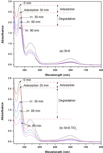
3.3 Degradation of dyes
Fig. 6 shows the time series of TBA degradation using
SnS and SnS-TiO
2composites under visible light irradi- ation. The spectra for the TBA solution after visible light irradiation show the relative degradation yields at different irradiation times. The decrease in dye concentration continued with an oppositely gentle slope, which was due to visible light irradiation. Two steps are involved in the photocatalytic decomposition of dyes; the adsorption of dye molecules and degradation. After adsorption in the dark for 30 mins, the samples reached adsorption- desorption equilibrium. In the adsorptive step, SnS and SnS-TiO
2composites showed different adsorptive effects with SnS having a little excellence adsorptive effect. A comparison of the decoloration effect of the catalysts showed that the degradation effect can be increased by an increase in the adsorption capacity. Fig. 6 represent the degradation of TBA with SnS and SnS-TiO
2in visible light from which it is clear that the concentration of TBA gradually diminishing with increasing time for all of samples. The decreasing concentration of TBA in the photocatalytic reaction was used to evaluate the activity of SnS and SnS-TiO
2composites. The spectra of the dye solution show the relative degradation yields at Fig. 5. N
2adsorption-desorption isotherms for (a) SnS and (b) SnS-
TiO
2.
Fig. 6. Degradation of TBA under visible light, (a) SnS and (b)
SnS-TiO
2.
different time intervals. Moreover, the dye solution increas- ingly lost its color intensity as the dye concentration continued to decrease. The decrease in concentration was evaluated at the λ
maxvalues of the dyes which were determined from the absorption spectra of the dyes.
However, due to confidential issues of the manufacturing company, information about the textile dyes TBA the detailed reference was not found. But the UV/Vis spec- troscopic analysis and the rate determination of the drastic diminish in the dye concentration clearly indicated photocatalysis.
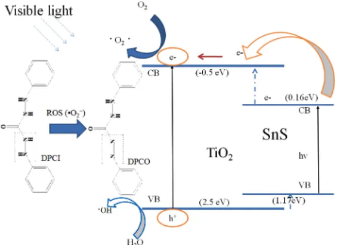
Fig. 7 Is the UV-vis spectra of OPCO extract liquors in the presence of SnS-TiO
2composite under visible light irradiation. 1,5-diphenyl carbazide (DPCI) can be oxidized by oxidizing substances into 1,5-diphenyl car-bazone (DPCO). Under visible light irradiation, the SnS-TiO
2samples turns into the excited state. That is, some elec- trons are transited from valence band (VB) to conduction
band (CB). Simultaneity, the electron-hole pairs form on the surface or in the inner of SnS-TiO
2samples.
21,22)The electrons and holes react with the molecular oxygen (O
2) dissolved in aqueous solution and water molecules (H
2O) absorbed on the surface of SnS-TiO
2particles, respect- ively, producing the superoxygen radical anions (•O
2−) and hydroxyl radicals (•OH). These •OH can oxidize 1,5- diphenyl carbazide (DPCI) into 1,5-diphenyl carbazone (DPCO). The DPCO can be extracted by the solvent of benzene and show an absorbance at 560 nm wavelength.
Sequentially, the produce and output of •OH can be easily detected, and the photodegradation activity can be easily detected. In Fig. 7 can be seen that, under visible light irradiation, the absorption peaks of DPCO around 560 nm show an obvious increase compared with the corresponding ones without any irradiation. And that, samples under visible light irradiation for different times the DPCO solution exhibits different absorbance. For DPCO result, exhibited SnS-TiO
2nanoparticles has good generation of reactive oxygen species effect.
In case of SnS coupled system, semiconductor coupled with two components has a beneficial role in improving charge separation and enhance TiO
2in response to ultra- sonic. In case of addition of SnS as a new matter, the excited electron from the SnS particles are quickly transferred to TiO
2particle due to the conduction band of SnS is 0.16 eV which is −0.5 eV more than that of TiO
2.
23-25)While the electrons formation excited from SnS are injected into the conduction band of TiO
2and then scavenged by molecular oxygen O
2to produce the superoxide radical anion
•O
2-. This transfer of change should enhance the oxidation of the adsorbed organic substrate. Fig. 8 is the illustration is the mechanism for the degradation of pollutants on SnS-TiO
2interface.
4. Conclusions
The SnS-TiO
2nanocomposites were synthesized using a cheap and less toxic SnCl
2as the precursor. XRD and TEM results show that the prepared product is acanthite phase SnS nanoparticles and has a grain size of 30 nm in diameter. The adsorption and surface properties as struc- tural and chemical composition of the SnS-TiO
2com- posites were investigated. UV-vis spectra demonstrated the strong absorption band across the whole visible light region, indication that SnS and SnS-TiO
2is a kind of an excellent solar energy conversion material. It is demon- strated that SnS-CNT nanocomposites possess high photo- catalytic activity under visible light, which may be ascribed to the strong visible light absorption and its efficient multiple exciton generation under the excitation of light irradiation with the higher energy than the band gap. The quantities of generated hydroxyl radicals can be Fig. 7. UV-vis spectra of OPCP extract liquors in the presence of
SnS-TiO
2.
Fig. 8. Schematic diagram of the catalyst growth machanism,
separation of photogenerated electrons and holes on the SnS-TiO
2interface.
analysis by DPCO degradation. Undoubtedly, the novel nanocomposites could provide an alternative pathway for the production of environmentally benign photocatalysts exclusive for visible light irradiate activation.
References
1. O. K. Dalrymple, E. Stefanakos, M. A. Trotz and D. Y.
Goswami, Appl. Catal. B: Environ., 98, 27 (2010).
2. P. Xu, T. Xu, J. Lu, S. M. Gao, N. S. Hosmane, B. B.
Huang, Y. Dai and Y. B. Wang, Energy Environ. Sci., 3, 1128 (2010).
3. S. Bagwasi, B. Z. Tian, J. L. Zhang, and M. Nasir, Chem. Eng. J., 217, 108 (2013).
4. K. K. Akurati, A. Vital, J. P. Dellemann, K. Mitchalow and T. Graule, Appl. Catal. B, 79, 53 (2008).
5. X. Chen and S. S. Mao, Chem. Rev., 107, 2891 (2007).
6. C. Burda, Y. Lou, X. Chen, A. Samia, J. Stout and J.
Gole, Nano Lett., 3, 1049 (2003).
7. O. K. Dalrymple, E. Stefanakos, M. A. Trotz and D. Y.
Goswami, Appl. Catal. B: Environ., 98, 27 (2010).
8. S. Jothivel, R. Velmurugan, K. Selvam, B. Krishnakumar and M. Swaminathan, Sep. Purif. Technol., 77, 245 (2011).
9. P. S. Tang, H. F. Chen, F. Caom G. X. Pan, K. Y. Wang, M. H. Xu and Y. H. Tong, Mater. Lett., 65, 450 (2011).
10. Z. D. Meng, T. Ghosh, L. Zhu, J. G. Choi, C. Y. Park and W. C. Oh, J. Mater. Chem., 22, 16127(2012).
11. J. Wang, Y. W. Guo, B. Liu, X. D. Jin, L. J. Liu, R. Xu, Y. M. Kong, B. X. Wang, Ultrason. Sonochem. 18, 177
(2011).
12. S. Y. Cheng, Y. Q. Chen, Y. J. He and G. N. Chen., Mater. Lett., 61, 1408 (2007).
13. V. Ramaswamy, N. B. Jagtap, S. Vijayanand, D. S.
Bhange and P. S. Awati, Mater. Res. Bull., 43, 1145 (2008).
14. X. W. Zhang, M. H. Zhou and L. C. Lei, Carbon, 43, 1700 (2005).
15. R. Mariappan, T. Mahalingam and V. Ponnuswamy, Optik, 122, 2216 (2011).
16. H. L. Zhu, D. R. Yang, Y. J. Ji, H. Zhang and X. F. Shen, J. Mater. Sci., 40, 591 (2005).
17. C. R. Sekhar, K. K. Malay and D. G. Dhruba, Thin Solid Films, 350, 72 (1999).
18. B. Ghosh, R. Roy, S. Chowdhruy, P. Banerjee and S.
Das, Appl. Surf. Sci., 256, 4328 (2010).
19. Z. D. Meng, L. Zhu, J. G. Choi, M. L. Chen and W. C.
Oh, J. Mater. Chem., 21, 7596 (2011).
20. M. D. Donohue and G. L. Aranovich, Fluid Phase Equilib., 158, 557 (1999).
21. C. Yang, W. Wang, Z. Shan and F. Huang, J. Solid State Chem., 182, 807 (2009).
22. Z. D. Meng, M. M. Peng, L. Zhu and W. C. Oh, Appl.
Catal. B; Environ,, 113, 141 (2012).
23. J. Ning, K. Men, G. Xiao, L. Wang, Q. Dai, B. Zou, B.
Liu and G. Zou, Nanoscale, 2, 1699 (2010).
24. H. Liu, Y. Liu, Z. Wang and P. He, Nanotechnology, 21, 105707 (2010).
25. B. S. Liu, X. J. Zhao, Q. N. Zhao, X. He and J. Y. Feng, J. Elec. Spec. Relat. Phenom., 148, 158 (2005).