Vol.15, No.4, pp.1-6 (2021)
A Study on the Nylon Wire Holding and Release Mechanism for Cube Satellites by Applying Constant Holding
KeonWoo Koo1,†
1Department of Aerospace and Software Engineering, Gyeongsang National University
Abstract
The non-explosive holding and release mechanism is used to prevent damage to the mission component caused by explosives when the deployment structure for Cube Satellites is separated. However, among the several types available, the non-explosive holding and release mechanism system using nylon wires depend on the nylon wire knot method and tightening power of the worker. Therefore, in this study, we conducted experiments with the operation of a new holding and release mechanism system by conceptualizing the Boa System Dial, which can provide a constant tightening force regardless of worker proficiency and deploying a imitational solar panel. In this study, the process of binding and unbinding with constant tension was recorded while applying the novel non-explosive holding and release mechanism using the Boa System Dial proposed. In addition, required advances are indicated for the application of the proposed system to actual Cube Satellites.
Key Words : Non-explosive Holding & Release Mechanism, Nichrome Burn Wire Release, Boa System Dial, Torque Spring
1. Introduction
Considering satellites, the device for holding the deployable structure of the satellite and also for separating the structure can be largely categorized into explosive holding and release mechanism system and non-explosive holding and release mechanism system [1].
In this study, we focus on cube satellites. Unlike the commonly discussed medium- or large-sized satellites, cube satellites are picosatellites with a size of 10 cm × 10 cm × 10 cm and a weight of less than 1 kg based on 1U [2].
For cube satellites with such a small dimension, if the explosive holding and release mechanism system typically used in medium- and large-sized satellites (Pyro) is used, the payload system, mission component for the mission of cube satellites, and the main body may be significantly damaged [3].
Therefore, this system is not adequate for use in this type of small satellites.
For this reason, non-explosive holding and release mechanism systems are usually employed for cube satellites as they cause comparatively less damage and failure than the
explosive holding and release mechanism system [4].
The non-explosive holding and release mechanism system can be further classified into different types of devices, which include the systems using shape memory alloy, paraffin, nylon wires, and heating wires (nichrome wires) [5].
Among these different methods, the non-explosive holding and release mechanism system using nylon wires can minimize damage and failure to the payload system and other equipment during holding and deployment of the structure in cube satellites. Thus, this method is mainly applied in cube satellites.
However, in the conventional non-explosive holding and release mechanism system with nylon wires, the first process of holding is performed manually, which may result in the application of a non-uniform tightening force depending on the difference in the knot method of the wire or the individual level of proficiency of the worker who performs the knotting [6-7].
In addition, the non-explosive holding and release mechanism system is unavoidably subject to the high-vibration environment of the launcher, which is used to release the satellite out of the atmosphere for space missions. During this process, the plasticity of nylon wires may lead to permanent longitudinal deformation and subsequent reduction of the tightening force.
Therefore, the holding and release mechanism system introduced in this study can resolve the problem of non-uniform tightening force at the initial stage of the holding process and Received: Jan. 13, 2021 Revised: Mar. 30, 2021 Accepted: Apr. 12, 2021
† Corresponding Author
Tel: E-mail: [email protected]
Ⓒ The Society for Aerospace System Engineering
***-****-****
the consequent differences in the holding performance by introducing a device called Boa System Dial. Moreover, to maintain the tightening force for constant holding, the combined use of the Boa System Dial and torque spring is proposed to address the decrease in the tightening force of the holding and release mechanism system.
The Boa System Dial is a device commonly seen in outdoor shoes for mountaineering. It is a device that can apply fastening and holding forces by simply turning the dial by hand without having to manually tie the knot of the shoes.
In this study, this simple method of tightening and operation of the Boa System Dial was reconfigured for application to the holding and release mechanism system for the deployment structure of cube satellites.
2. Method of applying and maintaining the constant holding force
2.1 Principle of the Boa System Dial
The operational mechanism of the Boa System Dial is described in Figs. 1 and 2. The method of holding the deployment structure using the Boa System Dial consists of grabbing and turning the top disk part of the Boa System Dial by hand, which results in the application of the holding force to the deployment structure.
In the process of holding, the two disks composed of teeth in right-angled triangle shape are engaged with each other and rotate in an oblique direction. In the right-angled part of the teeth, the rotation to the opposite direction of the previous rotation is disabled, which provides the binding in the single direction of the x-axis. Consequently, the towing and gradual holding of the deployment structure is possible due to the unidirectional rotation.
Fig. 1 Structure of the Boa System Dial [8]
Fig. 2 Towing Method for Nylon Wire [8]
In addition, nichrome wires, which are wires resistant to heating for the holding and release process, are installed in the nylon wire guide groove. Then, the nylon wire is guided to the Boa System Dial Top Disk by the nylon wire guide groove and while it is wound, the nylon wire is melted to release the holding force applied to the deployment structure.
2.2 Method with the use of the torque spring
In this section, to address the problem of the decrease in the tightening force of the holding and release mechanism system, which is caused by deformation of the nylon wires from the high-vibration environment of the launcher, we propose a method to retain the tightening force of the deployment structure using a torque spring.
The high-vibration environment is the extreme environmental condition of the launch load, consisting of sine, acoustic, random, and shock waves applied on the satellite from the launcher. In this context, the nylon wire of the holding and release mechanism system undergo deformation as the wire enters the plastic section, and the deformed nylon wires do not return to their original length [9].
If holding is maintained in this state, the tightening force will vary due to the change in the overall length of the stretched nylon wires. In this case, when the satellite is exposed to the high-vibration environment of the launcher in a state with weakened tightening force, there is a high risk of damage to the mission components of the satellite, including the deployment structure [10]. Therefore, the tightening force must be maintained constant in the holding and release mechanism system.
In the proposed method, the holding and release mechanism system uses a torque spring to maintain the tightening force even under the high-vibration environment.
Using the characteristics of unidirectional holding and rotation of the disk of the Boa System Dial, as can be seen from Figs. 3 and 4, the torque spring pin is rotated in the opposite direction to the direction of towing the nylon wire, and the torque can be stored.
As shown in Fig. 1, due to the influence of teeth in the shape
of right-angled triangle, the rotation in a single direction of the x-axis is free, whereas rotation in the opposite direction is not possible. If the tightening force is weakened due to the plasticity of nylon wires, the top disk of the Boa System Dial is rotated by the torque stored in the torque spring as described above.
This provides towing on the nylon wires, which have a longer length at this stage, thereby maintaining the tightening force.
Fig. 3 Method of Maintaining the Tension of Nylon Wires with Torque Spring_1 [8]
Fig. 4 Method of Maintaining Tension of Nylon Wires with Torque Spring_2
3. Design of experimental apparatus for the deployment experiment
3.1 Design of experimental apparatus for the deployment experiment with a deployment structure
The structure for this experiment was designed and implemented in advance to deploy a model solar panel structure based on a model cube satellite with a size of 2U.
The experimental setup for the deployment experiment with the deployment structure is shown in Fig. 5. In this setup, the structures expressed as a model solar panel are mounted on both sides and connected to the bottom structure with hinges, which enables the simulation of the process of deployment of the deployable structure such as the solar panel from a real cube satellite. When the holding and release mechanism system is operated under this setup, the nichrome wire, which is the heating wire resistance installed in the nylon wire guide groove in the Boa System Dial Top Disk, is burned. Thus, the nylon wire wound in the nylon wire guide groove melts; consequently, the solar panels that are bound to the top structure can be deployed sideways.
At this time, the model solar panel can be rapidly deployed after releasing the holding due to the hinge spring connected to the bottom structure.
Fig. 5 Experiment Tool for Deploying the Solar Panel Structure
3.2 Method of holding the deployment structure In the processes of holding the solar panel, which is a model deployment structure, there is an interference between structures due to the hinge used for deploying the solar panel and the M3 bolt used for fixing the solar panel to the bottom structure. To address this problem, M3 Bolt Guide Holes were added to the hinge of the bottom structure, as shown in Fig. 6.
In addition, when the solar panel is held, the M3 Guide Hole is combined with the M3 bolt, limiting the degree of freedom in the x- and z-directions, which improves the holding stability.
Therefore, the experimental setup was designed considering the interference between structures due to M3 bolts, resolving this issue and simultaneously providing more stability when holding the solar panel.
In addition, the most influential holding force in the y- direction, which has a direct effect on the solar panel deployment process, is applied using the Boa System Dial, which will be introduced in the next section.
The Boa System Dial, which is grabbed by hand and rotated in a single direction, can apply the final holding force in the y- direction by towing the nylon wire connected to the dial. That
is, in the design of this deployment experiment setup, we aimed to achieve the overall stable holding performance in the x-, y-, and z-directions.
Fig. 6 M3 Bolt Guide Hole 3.3 Towing and holding of the solar panel
Although the experimental setup was designed to apply the holding force in the x- and z-directions for more stable holding, as shown in Fig. 6, the holding force in the y-direction, which directly affects the holding and deployment of the solar panel, must be applied.
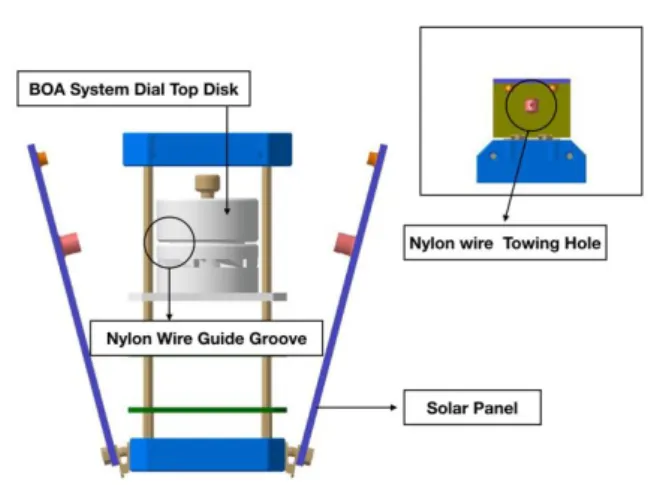
As shown in Figs. 7 and 8, the solar panels are towed by nylon wires connected to the Nylon Wire Guide Groove of the Boa System Dial Top Disk and the Nylon Wire Towing Hole of the solar panel. At this time, when the Boa System Dial Top Disk is rotated, nylon wires are wound around the Nylon Wire Guide Groove, and the solar panel connected to the nylon wires is towed and held in the y-direction.
For deployment of the solar panels, a model structure, power is supplied to the heating wire installed in the nylon wire guide groove of the Boa System Dial Top Disk structure, resulting in the cutting of the nylon wire.
Fig. 7 Solar Panel Guide Pin
Fig. 8 Nylon Wire Towing Hole
4. Results and Conclusion
4.1 Data accumulation and results of the deployment structure holding process
In this study, when a model solar panel contacts the top structure (top part of the cube satellite model) using a strain gauge, the data is received through the device configured, as shown in Fig. 9. In Fig. 10, after the guide pin of the solar panel contacts the strain gauge attached to the top structure of the main satellite body, the pressure applied to the strain gauge from the guide pin of the solar panels on both sides towed by the Boa System Dial is measured, and this enables to verify whether the Boa System Dial performs towing-tightening- holding with the same magnitude of force for the solar panels on both sides.
Fig. 9 Strain Gauge and Quarter Bridge Circuit
Fig. 10 Measuring Method during Boa System Dial Holding Process
Fig. 11 Measuring Values of the Holding Process As a result of the experiment, as can be seen in Fig. 11, data can be obtained for the process of applying constant holding using the method of Boa System Dial. In addition, the two sets of data obtained from both sides were similar.
The average strain gauge value data of the right side of the solar panel before holding was 10346, whereas that of the left side of the solar panel was 10345. Moreover, the values of strain gauge value data of the right and left sides of the solar panel were measured at 9057 and 9004, respectively.
Assuming that the value for the ideal holding condition is 9000, the error rate was calculated to be ±0.338% when holding two different sides of solar panels using the proposed holding and release mechanism.
4.2 Result of deployment experiment with a deployment structure applied with a constant holding
As shown in Fig. 12, the hinge spring installed in the hinge part of the bottom structure, which is the lower part of the cube satellite model, was involved in the deployment process of the model solar panel after cutting of the nylon wires, after which the solar panel was completely deployed.
Fig. 12 Solar Panel Deployment Procedure This deployment experiment with the deployment structure was performed mainly to show the feasibility of the holding and release function in the process of releasing the holding after the Boa System Dial applies the holding force to the deployment structure with a constant tightening force. The experiment was conducted by setting a limited environment in the vertical z-axis direction without considering the zero-gravity state and vibration environment.
As a result of the experiment, it was confirmed that after applying power to the nichrome wire (heating wire), nylon wires were melted at 0.07 s, the holding of the solar panels on both sides was released, and the solar panels were completely deployed at 0.36 s.
4.3 Conclusion
In this study, we applied the operational mechanism of Boa System Dial to address the problem of the conventional non- explosive holding and release mechanism system with nylon wires, in which different tightening forces and knot methods are applied depending on the proficiency of the worker, hindering the application of a constant holding force.
In addition, in the process of contacting and holding the solar panel to the main body of the model cube satellite through the holding and release mechanism system, the strain gauge mounted on the top structure of the cube satellite model was used to obtain data to examine whether the model solar panels are held with the same magnitude of towing force on both sides.
Furthermore, the commercial Boa System Dial is miniaturized to be applied to clothes and shoes. Thus, it is a reasonable option in terms of mass and space to be applied to the payload system of cube satellites. In this study, for convenience in taking photos and intuitive description, the size of the Boa System Dial was designed to be large. However, for applications to a real cube satellite, sufficient considerations should be made in terms of mass and space.
5. Discussion
In this study, we focused on two issues: 1) the problem of the conventional non-explosive holding and release mechanism system with nylon wires, in which different tightening forces
are applied while the initial holding process is performed manually, hindering the application of a constant holding force;
2) the weakening of the initially applied tightening force as the nylon wire enters the plastic section and the length of the wire is permanently stretched due to the high-vibration environment of the launcher. To address the first issue, we proposed the use of the Boa System Dial and obtained the experimental data for deployment structure holding using the proposed method. For the second issue, we used a torque spring to maintain the constant holding force.
Moreover, using the proposed holding and release mechanism system, after holding the deployment structure, power was applied to the nichrome wire to release the holding force, leading to the successful deployment of the solar panels (model deployment structure).
However, the conventional non-explosive holding and release mechanism system with nylon wires has high reliability due to the simple configuration of a single component, such as a heating wire or a heating diode, and also the simplicity in the structure. In contrast, in the proposed system, the number of components is increased by more than two times, which may lead to the decrease in the reliability of the mechanism [10].
Furthermore, to demonstrate only the feasibility of the holding and release mechanism system proposed, the experiment in this study was conducted with a limited environment setting for the z-axis. In future research, the appropriate process for reducing the size to apply to the real cube satellite is necessary and the deployment experiment should be performed in the setting including the x-axis and y- axis dimensions. Thus, it is considered that the data demonstrate the validity of the holding and release performance of the proposed mechanism system.
Acknowledgement
This paper is a revised and supplemented version of the a paper presented at the 2020 Fall Conference of The Society for Aerospace System Engineering.
References
[1] H. U. Oh and S. C. Kwon, “Structural design of cube satellite by using heating wire cutting type separation mechanism,” J. of The Korean Society for Aeronautical and Space Sciences, vol. 31, no. 9, pp. 720-725, 2013.
[2] J. T. Kim, Y. S. Kim, S. W. Seo, Y. H. Kim, and Y. K.
Chang, “A conceptual design of HAUSAT_1 (CubeSat) satellite,” International Journal of Aeronautical and Space Sciences , vol. 3, no. 1, pp. 940-946, 2002.
[3] H. U. Oh and M. J. Lee, “Performance verification of separation nut type non-explosive separation device for cube satellite application,” J. of The Korean Society for Aeronautical and Space Sciences, vol. 33, no. 3, pp. 1234-
1245, Dec. 1993.
[4] A. Thurn, S. Huynh, S. Koss, P. Oppenheimer, S. Butcher, J. Schlater, and P. Hagan, “A nichrome wire release mechanism for CubeSats,” The 41st Aerospace Mechanism Symposium, pp. 479-488, 2012.
[5] M. J. Lee, Y. K. Lee, S. J. Kang, and H. U Oh, “Launch an on-orbit environment verification test of fight model of hinge driving type holding and release Mechanism based on the Burn wire release,” J. of The Korean Society for Aeronautical and Space Sciences, vol. 55, no. 3, pp. 274- 280, 2016.
[6] S. H. Woo and J. H. Han, “Mid frequency shock response determination by using energy flow method and time domain correction,” Shock and Vibration, vol. 20, no. 5, pp.
847-862, 2013.
[7] Y. H. Park, J. S. Go, B. G. Chae, S. H. Lee, and H. U. Oh,
“Functional verification of nylon wire cutting-type holding
& release mechanism for 6U cube sat’s,” J. of The Korean Society for Aeronautical and Space Sciences, vol. 44, no.
10, pp. 867-875, 2018.
[8] K. W. Koo, “Deployment structure holding & release mechanism for cube satellites with actives wire tension control,” The Society for Aerospace System Engineering Fall Conference, 2020.
[9] K. H. Lee, J. H. Kim, S. B. Lim, and S. W. Choi, “Study on satellite separation system application of launch vehicle,”
The Korean Society for Aeronautical and Space Sciences, pp. 2102-2015, November 2012.
[10] J. H. Kim, H. Y. Moon, S. H. Woo, Y. S. Chun, and S. R.
Lee, “A study on LV mechanical interface for advance EO satellite,” The Korean Society for Aeronautical and Space Sciences, vol. 32, no. 3, pp. 1106-1107, April 2008.
![Fig. 2 Towing Method for Nylon Wire [8]](https://thumb-ap.123doks.com/thumbv2/123dokinfo/5100838.326473/2.892.95.404.780.1023/fig-towing-method-nylon-wire.webp)
![Fig. 3 Method of Maintaining the Tension of Nylon Wires with Torque Spring_1 [8]](https://thumb-ap.123doks.com/thumbv2/123dokinfo/5100838.326473/3.892.146.398.321.576/fig-method-maintaining-tension-nylon-wires-torque-spring.webp)