Bandwidth-Efficient Precoding Scheme for Downlink Smart Utility Networks
B.W. Kim
†ABSTRACT
The emerging smart utility networks (SUN) provide two-way communications between smart meters and smart appliances for purpose of low power usage, low cost, and high reliability. This paper deals with a bandwidth-efficient communication method based on the hidden pilot-aided scheme using a precoder in downlink SUN suitable for high-rate multimedia applications. With the aid of the design of a precoder and a superimposed hidden pilot, it is possible to estimate the channel without loss of bandwidth.
In the channel estimation procedure, the inevitable data interference, which degrades the performance of channel estimation, can be reduced by the precoder design with an iterative scheme. Computer simulations show that the proposed scheme outperforms the conventional method in terms of achievable data rate, especially when a large number of subcarriers are employed.
Key words: Smart Utility Networks, Precoding, Bandwidth Efficiency
※ Corresponding Author : Byung Wook Kim, Address:
(712-701) 50, Gamasil-gil, Hayang-eup, Gyeongsan-si, Gyeongsangbuk-do, Korea, TEL : +82-53-600-5524, FAX : +82-53-600-5539 , E-mail : [email protected]
Receipt date : Apr. 25, 2014, Revision date : Jun. 13, 2014 Approval date : Jul. 2, 2014
†
School of Electrical and Railway Engineering, Kyungil University
1. INTRODUCTION
The increasing interest in modern smart grid re- quires a new technology for providing the two- way communication between the consumer and the utility at the appliance/meter level [1-6]. This will enable the consumer to continuously monitor pow- er usage and make instantaneous decisions to con- trol electric devices at consumers’ homes or offices to reduce energy usage, cost and increase service reliability. Smart utility networks (SUN), a sub- ordinated network in the smart grid, consist of smart home appliances and meters equipped with radio terminals. Smart devices in SUN can auto- matically control power consumption during peak and offpeak load times according to the demand requirement. This will ensure that power is not utilized by the appliance when the cost of power consumption is expensive. In addition, SUN may support other functionality needs, such as multi-
media data transmission from substations to smart devices in addition to normal control data.
IEEE 802.15.4g specification for Physical Layer (PHY) is built for smart devices of SUN [7].
Among the various alternative PHY designs, mul-
ti-rate and multi-regional orthogonal frequency
division multiplexing (MR-OFDM) was designed
to provide higher data rates in channels that have
significant delay spread. Due to the fast growth of
demands on multimedia services of smart devices,
SUN are expected to support high data rate
applications. In addition, in order to reduce the
power consumption and interference during com-
munications between smart devices, a trans-
mission method to shorten transmission time is
required. To solve these problems, multiple-input
multiple-output (MIMO) systems can be a viable
solution for high data rate communications over
SUN. As the downlink of the SUN with dense
smart meters will act as the bottleneck link, an ef-
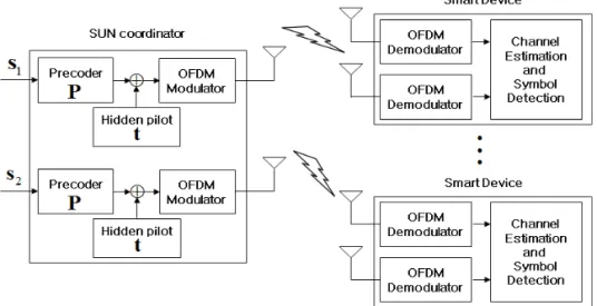
Fig. 1. The downlink smart utility network.
ficient usage of downlink wireless resources is im- portant to provide high quality of communication services.
In the wireless SUN, a pilot-symbol-aided mod- ulation (PSAM) scheme, one of the most widely used schemes in cellular systems, can be used to estimate the channel state information (CSI) ex- ploiting pilot symbols that are previously known at the user terminal [8]. Accurate channel esti- mates can be obtained by using the judiciously placed pilots [9], whereas it consumes bandwidth which is valuable in wireless communications.
Although blind channel estimation [10] offers a bandwidth-efficient method exploiting statistical and other properties of the data, it has its inherent shortcomings, such as slow convergence and phase ambiguity. An alternative method is the super- imposed training (ST) scheme [11-12] has a virtue of no loss in information rate at the expense of data power. However, this method may degrade the performance of channel estimation due to the effect of inherent interference of data. Use of a hidden pilot based precoding scheme can be a feasible sol- ution to this problem, as it removes inevitable un- known data interference with the aid of the design of a precoding and a ST sequence [13].
In this paper, we propose a bandwidth efficient precoding scheme for downlink SUN for achieving
high data rates. Considering different designs of a precoder and a superimposed hidden pilot per transmit antenna in smart devices, spatially multi- plexed data can be successfully recovered. In addi- tion, due to the spreading effect of the information data over the total available bandwidth using a precoder, it is possible to provide high frequency diversity. The performance gain of achievable data rate becomes significant when a large number of subcarriers is employed.
This paper is organized as follows. In Section 2, a system model of the proposed scheme is introduced. Section 3 presents the channel estima- tion and symbol detection. The results of computer simulations are shown in Section 4. Finally, con- clusions are drawn in Section 5.
2. SYSTEM MODEL OF A HIDDEN PILOT- AIDED PRECODING SCHEME
2.1 MR-OFDM system model
We consider a downlink transmission from an access point, such as a coordinator or a router, equipped with two transmit antennas, to smart devices, such as in-home and metering devices, al- so having two receive antennas, depicted in Fig.
1. At each transmit antenna, a MR-OFDM modu-
lator followed by the proposed hidden pilot aided
precoder is used. Let be the total number of sub- carriers in one OFDM symbol. Remind that appli- cation of block transmission with a cyclic prefix (CP) over a time-dispersive channel can be mod- eled as transmission over a channel with a circu- lant channel matrix. And the length of the CP is set to be equal to the number of non-zero taps of the impulse response for each channel.
After removing the CP at the ′ -th smart devi- ce's -th receive antenna, we obtain an × vector
′, which can be written as
′
′
′ (1)
where
…
is an ×
precoded transmit symbol block for the -th as- signed device, from the -th transmit antenna.
′
is the × downlink channel matrix, which is a circulant matrix with the first column given by
′…
, and
′
′
′…
′
is the × vector representing the length channel impulse response from the coordinator’s -th transmit antenna to the -th receive antenna of the
′ -th smart device. The × discrete Fourier transform (DFT) matrix
has an entry
… . We assume that
′
′
′…
′
is additive white Gaussian noise (AWGN), whose elements are in- dependent and identically distributed (i.i.d.) zero mean complex Gaussian random variables with variance
.
2.2 Design of a precoder and a superimposed hidden pilot
In this subsection, we derive the design of a pro- posed scheme based on a precoder and a ST symbol. Since a training sequence for channel esti- mation is simply added to the precoded data, there exists mutual interference between them. To miti- gate inherent mutual interference, the precoder based on orthogonal polyphase sequences [13],
which have good periodic autocorrelation and crosscorrelation properties, is exploited. These properties are utilized to eliminate the interference between the data and the hidden pilot guaranteeing almost no loss of transmit data rate. To generate these sequences, the length of a sequence is set to
, where is prime and is an integer.
Then, the (=
) numbers of polyphase sequence sets such that
…
, where
…
, can be generated by
× (2)
Then, we can split the polyphase sequence sets into two parts, the sequence for a precoder and for a hidden pilot. Design of the precoder matrix and the pilot vector can be expressed as follows:
⋅′
′
…′
⋅′
(3)
where ′
is an × vector and the
× discrete Fourier transform (DFT)
matrix
has an entry
… . We design the transmit symbol block using the above precoder and hidden pilot with regard to the subcarrier and the antenna index. To support the orthogonality of different antennas' pilot signals for channel prediction, we consider disjoint sets of tones where hidden pilot symbols are included or not in transmit symbol at each antenna. First, we set the × subcarrier index matrix
se- lecting odd and even index vectors, respectively.
Here, we assume that an × information data block for the -th smart device from the -th transmit antenna
is the i.i.d. zero mean complex Gaussian random vector with covariance
. We also assume that
where
denotes the transmit pilot power in one symbol block.
As previously mentioned, to locate disjoint sets
of tones, which include hidden pilots or not, in the
Fig. 2. Periodic crosscorrelation property of the poly- phase sequences with k-shifted and n-shifted vectors.
transmit symbol at each antenna, we design the precoded vector
as
(4) where
and
are the odd and even index information data blocks from
, respectively. We then obtain the transmit symbol block
which is shown as
(5) where
is a subcarrier mapping matrix which has the following conditions:
i f
i f ≠ (6)
Note that we apply equidistantly-located sub- carrier mapping which spreads the signal over the total available subcarriers to obtain frequency di- versity as much as possible. It is clear from Eq.
(5) that the proposed design of hidden pilots im- poses good bandwidth efficiency, because we can locate information data over the available MR- OFDM subcarriers and pilots are simply added to certain subcarriers determined by
or
.
At the ′ -th smart device's -th receive anten- na, an × vector
′
is selected by the sub- carrier demapping matrix
′
for channel esti- mation and symbol detection, which is given by
′
′
′
′
′
′
′
′
′
′
′(7)
′
′
′
′
′
′
′
′
′
′
′(8)
where
′
is an × diagonal chan- nel matrix whose principal diagonal components are the elements of
′
, which is the frequency response of a time domain channel
′
.
3. CHANNEL ESTIMATION AND SYMBOL DETECTION
3.1 Channel Estimation
At smart devices using the hidden pilot-aided precoding scheme, channel estimation can be car- ried out by preprocessing received signals in order to reduce the interference between the data and the hidden pilot. The preprocessing is based on the correlation properties of the designed precoder and the hidden pilot. Using the hidden pilot and the in- verse DFT matrix for preprocessing, the interfer- ence
′
consisting of data symbols is suppressed as
′
′
′
′
′
′
′
′
′
′
′
′
′
(9)
where
, is an × circulant matrix with the first column ,
′is an
× circulant matrix with the first column
′
…
and
′
is a modified noise vector, i.e.,
′
′. We have used the fact that
′
′due to the commutativity of circular
convolution. If we let
be a column-wise circu- lant matrix with the -th column of as the first column, which we denote as
,
′
is equivalent to
′.
As depicted in Fig. 2, the polyphase sequence has a good periodic crosscorrelation property.
From the figure, we can notice that
ap- proaches 0 for all , and thus, we can effectively remove the data interference
′. Then, we can es- timate the time domain channel by the linear MMSE channel estimator [14] given by
′
′
′
′
′
′
′
′
′
′
′
′
′ (10) Now, let us define the channel estimation error as
′
′
′and the corresponding mean square error (MSE) can be expressed as
′
′
′
′′ ′ ′ ′′ ′′
′
′ ′
′
′
(11) where
′
is the variance of noise
′
. In fact,
shows a good periodic autocorrelation feature, i.e.,
→ where is a constant and is the identity matrix.
3.2 Symbol Detection
Using the estimated CSI, the received signal vector
′
is equivalently expressed as
′
′
′
′
′
′ (12) where
′
′
′
′
′ (13)
′ and
′ denote diagonal matrices whose main diagonals are
′
and
′
, respectively.
Since we consider smart devices equipped with two antennas, we can combine two received signal vectors into one signal vector, that is,
′
′
′
′
(14)
where
′
′
′
′
′
(15)
′
′
′
′
′
′
′
′
′
. We consider a linear MMSE receiver [12] to de- tect information data from the received symbols.
Then, symbol detection is presented as
′
′
′
′
′
′
′
′
′
′
′
′
(13)
where
is the total data symbol power in one block. After finishing linear MMSE symbol de- tection, we can additionally suppress the residual of data interference components by using an iter- ative algorithm, which further decreases
′
, with the help of the detected symbol and the estimated channel. Carrying out the iterative algorithm, a new pre-processed data block
′
can be written as
′
′
′
′(14)
where
′
is the × circulant matrix with the first column
…
. It was observed by numerical simulations that the iterative algo- rithm for accurate channel estimation converges rapidly within a couple of iterations.
4. SIMULATION RESULTS
In this section, the performance of the proposed
scheme is evaluated under SUN. For the purpose
of comparison, a PSAM scheme is presented as the
conventional scheme. As shown in the IEEE
802.15.4g PHY specification [5] for SUN, the total
subcarrier number in MR-OFDM is set to 128
for the SUN-OFDM option 1 and 64 for the option
2. It is assumed that a coordinator transmits data
0 5 10 15 20 25 30 10-4
10-3 10-2 10-1 100
Eb/No [SNR per bit]
Mean Square Error
Channel Estimation Error
prop. scheme w/ iter.
prop. scheme w/o iter.
analysis of prop. scheme conv. PSAM
Fig. 3. Performance comparison of channel estimation of the proposed hidden pilot-aided precoding scheme and the conventional PSAM.
0 5 10 15 20 25 30
0.55 0.6 0.65 0.7 0.75 0.8 0.85 0.9 0.95
Eb/No [SNR per bit]
Achievable Data Rate [bit/s/Hz]
Achievable Data Rate
prop. scheme in option 1 prop. scheme in option 2 conv. PSAM in option 1 conv. PSAM in option 2
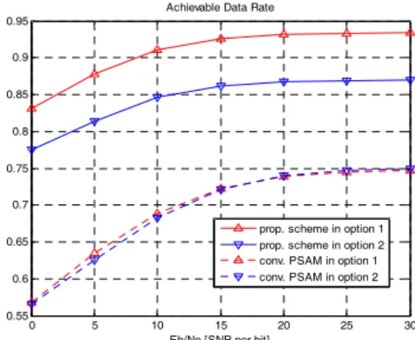
Fig. 4. Achievable data rate comparison for the SUN- OFDM option 1 and option 2.
to two smart devices, where each device is equip- ped with two antennas. The channel is randomly generated at each Monte-Carlo run and is assumed to be Rayleigh with length for OFDM option 1 and for OFDM option 2. Without loss of generality, the number of the disjoint pilot symbols in conventional PSAM is set to the number of channel length.
The channel estimation performance of the pro- posed scheme based on a hidden pilot is compared to the performance of conventional PSAM in Fig.
3. Here, the pilot power ratio loaded to the hidden pilot is set to 0.7 and the SUN-OFDM option 1 is considered. Note that the analysis of channel esti- mation error derived in Eq. (11) is similar to the curve obtained with Monte Carlo simulations. In addition, it is shown that the channel estimation performance of the proposed scheme is better than the PSAM scheme in the low SNR region because the proposed one uses a more sufficient number of pilots compared to PSAM. However, in the high SNR, the channel MSE of the proposed scheme is worse since the fact that
→ is not perfectly satisfied, and thus, it degrades the channel estima- tion performance. Such a residual interference can be reduced by iteratively updating the detected symbols and the estimated channel, as shown in Fig. 3.
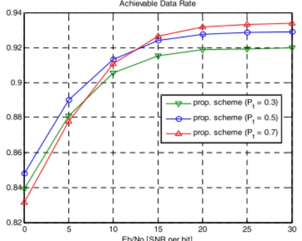
Fig. 4 displays the achievable data rate perform- ance of the proposed scheme with regard to the power allocated to the hidden pilot. The power ratio loaded to the hidden pilot varies from 0.3 to 0.7 in the SUN-OFDM option 1 scenario. When SNR is low, the performance of channel estimation has a minor effect on the achievable data rate due to the severe communications condition. However, in the high SNR region, the imperfect channel prediction leads to the notable performance degradation. To obtain high achievable data rate for the high SNR case, the use of pilot power
is desirable.
The comparison of the achievable data rate be-
tween the proposed scheme and the conventional
PSAM for the SUN-OFDM option 1 and option 2
are shown in Fig. 5. For both cases, the proposed
scheme outperforms the conventional PSAM under
overall SNR region. For channel prediction, the
proposed scheme does not waste valuable band-
width, while the PSAM scheme consumes pilot
tones which degrades bandwidth efficiency. It can
be observed that the proposed scheme provides
better achievable data rate in option 1, where a
large number of subcarriers are considered, than
the one in option 2. Since the precoder in the pro-
posed scheme spreads each symbol over the avail-
able frequency domain and achieve a high degree
of frequency diversity, the use of a large number
of subcarriers, based on the SUN-OFDM option 1,
0 5 10 15 20 25 30 0.82
0.84 0.86 0.88 0.9 0.92 0.94
Eb/No [SNR per bit]
Achievable Data Rate [bit/s/Hz]
Achievable Data Rate
prop. scheme (Pt = 0.3) prop. scheme (Pt = 0.5) prop. scheme (Pt = 0.7)