Rail Inspection Using Noncontact Laser Ultrasonics
Nak-Hyeon Kim*, Hoon Sohn*✝ and Soon-Woo Han**
Abstract In this study, a noncontact laser ultrasonic system is proposed for rail defect detection. An Nd-Yag pulse laser is used for generation of ultrasonic waves, and the corresponding ultrasonic responses are measured by a laser Doppler vibrometer. For the detection of rail surface damages, the shape of the excitation laser beam is transformed into a line. On the other hand, a point source laser beam is used for the inspection of defects inside a rail head. Then, the interactions of propagating ultrasonic waves with defects are examined using actual rail specimens. Amplitude attenuation was mainly observed for a surface crack, and reflections were most noticeable from an internal damage. Finally, opportunities and challenges associated with real-time rail inspection from a high-speed train are discussed.
Keywords: Noncontact Laser Ultrasonics, Rail Inspection, Damage Detection, High-Speed Train
[Received: November 7, 2012, Revised: December 3, 2012, Accepted: December 7, 2012] *Department of Civil and Environmental Engineering, KAIST, 373-1, Guseong-dong, Yuseong-gu, Deajeon 305-701, Korea **Korea Railroad Research Institute, 176 Cheoldo Bangmulgwan-ro, Uiwang, Gyeonggi-do, 437-757, Korea ✝Corresponding Author:
ⓒ 2012, Korean Society for Nondestructive Testing
1. Introduction
In this study, we propose a noncontact laser ultrasonic system for detection of surface and subsurface detects in rail heads. High-speed trains in Korea are gaining popularity as effective and timely means of transportation. As the speed and frequency of the high-speed trains increase, the possibility for rail damage also increases. To inspect rail damage, several techniques have been developed including visual inspection, conventional NDT techniques, specialized inspection trains, and noncontact scanning techniques [1]. The majority of inspection still relies on visual inspection, which is labor intensive and time consuming.
Conventional NDT techniques are very reliable, but their applications are often limited to local inspection because they require couplants such as water or contact type transducers. For long range rail inspection, specialized inspection vehicles equipped with visual cameras and/or laser scanning devices have been developed and
commercialized. Here, vision-based devices can only defect surface damage, and rapid image processing can be a daunting task. The laser system often utilizes noncontact acoustic transducers for measurement of leaky guided waves, but the stand-off distance between the acoustic transducer and the rail surface is limited less than 8 cm in static configuration [2].
In this study, a noncontact laser based rail inspection system is proposed. Because the proposed system utilizes laser beams for both ultrasonic generation and sensing, the stand-off distance from the rail surface can be significantly increased. Furthermore, the possibility of detecting subsurface damages as well as surface defects has been demonstrated.
This paper is organized as follows. First, the
configuration of the proposed laser ultrasonic
system is described in Section 2. Then, the
experimental setup and test results are reported
in Sections 3 and 4, respectively. Finally,
conclusions and discussion for high-speed train
operation have been provided.
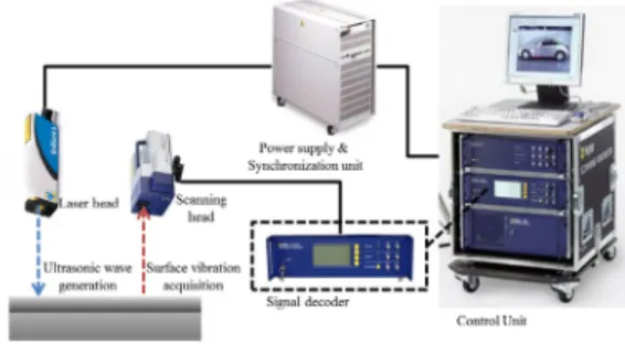
Fig. 1 Overall configuration of the proposed laser ultrasonic system
2. Noncontact Laser Ultrasonic System 2.1 Overall System Configuration
Fig. 1 shows the overall configuration of the proposed laser ultrasonic system for rail inspection. The proposed system consists of two subcomponents: an Nd-Yag pulse laser and a laser Doppler vibrometer. A high-power laser focused into a rail surface creates ultrasonic waves through localized heating. Then, the generated ultrasonic waves propagate along the rail and measured by a laser Doppler vibrometer.
The operation of both laser components are controlled by a centralized control unit, and the measured time signals are also collected and analyzed by this control unit. More details for each subcomponent are provided below.
2.2 Ultrasonic Generation
When a high-power laser is exerted into an infinitesimal area, it causes localized heating of the material and thermal expansion.
Subsequently, this instantaneous and localized expansion of the material results in propagation of elastic waves [1]. However, if the power level per unit surface area is too high, it can cause burning of the materials called ablation [2]. Therefore, laser parameters such as the peak power, pulse duration, beam size need to be carefully adjusted to avoid ablation and
properly generate ultrasonic waves. In this study, a commercially available Nd-Yag pulse laser (Brilliant B from Quantel) is used. This laser system has 1064 nm wavelength, 850 mJ output energy, and a repetition rate of 10 Hz. Then, the pulse duration and laser beam diameter are set to 6 ns and 9 mm, respectively.
2.3 Ultrasonic Measurement
Ultrasonic waves are measured using a laser Doppler vibrometer, which is one class of heterodyne laser interferometers [5]. When an incident laser beam is reflected from a vibration surface, the frequency of the reflected laser beam is shifted in accordance with the out-of-plane velocity of the target surface based on the Doppler Effect. Therefore, by tracking the frequency shift of the reflected laser beam, the out-of-place velocity of the vibrating surface is measured. Then, displacement or accelerations are estimated from the velocity. Here, the noise level is critical for proper measurement of ultrasonic waves since the magnitude of the expected out-of-plane ultrasonic velocity and displacement are in the order of 0.1~10 m/s and less than 10 nm. Note that the noise or signal-to-noise level of the laser vibrometer is heavily affected by the incident angle of the laser beam and the surface condition of the material. The laser beam is placed normal to the rail surface to maximize the intensity of the return signal, and the effect of the surface condition is invested later in the experiments. In this study, an off-the-shelf laser vibrometer available from Polytec (PSV-400) is used. This device uses a HeNe laser source with 632 nm wavelength and power less than 1 mW.
Furthermore, the laser coherence length and
sampling frequency are over 40 cm and up to
1.5 MHZ, making it possible to measure
ultrasonic waves in 10 to 100 kHz ranges with
a long stand-off distance from the rail surface.
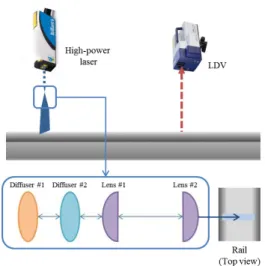
Fig. 2 Generation of a liner source laser beam
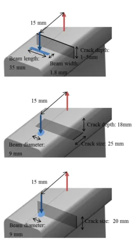
Fig. 3 Dimensions of the tested rail specimens
Fig. 4 Detailed test configuration for noncontact laser ultrasonic measurement
2.4 Generation of a Line Source Laser Beam
For surface damage detection, the shape of the excitation laser beam is expended into a line source using multiple optical devices as shown in Fig. 2. First, the beam size is extended in one direction using diffuser 1 in the figure, and then the beam intensity across the extended beam is unified using diffuser 2. The length of the extended line source is adjusted by controlling the distance between diffuser 1 and the rail surface. The thickness of the line source is varied by moving the positions of cylindrical convex lenses (lenses 1 and 2) with respect to the rail surface.
3. Experimental Setup
The effectiveness of the proposed laser inspection system is examined using actual rail specimens. In this section, the specification of the used rail specimens and test configurations of the laser ultrasonics system are described.
3.1 Test Specimens
The tested rail specimens (1 m*2ea and 2 m*1ea) are provided by Korea Railroad Research Institute. The specification of the rail specimens are provided in Fig. 3.
3.2 Test Configuration
As shown in Fig. 4, the Nd-Yag laser beam
is exerted near one end of the inspecting
section, and the corresponding response is
measured by the LDV aimed at the other end of
the section. The distance between the excitation
and sending laser beams are kept to be 15 mm
throughout the experiment. This distance is
determined to maximize the arrival time
difference between the Rayleigh and
bulk(longitudinal) waves and at the same time
Fig. 5 Damage types investigated in this study:
surface crack (top), subsurface horizontal notch (middle), subsurface vertical notch (bottom)
Fig. 6 Configurations of point and line source laser beams
to minimize the interference with reflections from the rail boundaries. This common configuration is used for both surface and subsurface defection detection. The simulated surface crack and subsurface defects are shown in Fig. 5. The only difference in the test configuration for detecting these two different damage types is the shape of the excitation laser beam as described below.
3.3 Line and Point Source Excitations
For the surface crack detection, a line source excitation laser beam is used to generate a uniform wave front. On the other hand, a point source beam is used for subsurface defect
detection. For fair comparison, the surface areas exposed to these two laser beams are kept to be same. That is, the point beam size is 63.62 mm^2 = 9^2*pi/4, and the area of the line source is 63 mm^2 = 35*1.8.
4. Experimental Results
Surface (Rayleigh) waves and bulk (longitudinal) waves are the primary waves generated by the proposed laser ultrasonic system.
A surface crack is detected using the Rayleigh waves created by the line source laser beam, and a subsurface defect is identified using the evanescent waves generated by the point source beam.
4.1 Surface Damage Detection
Here, the effect of the increasing crack
depth on the measured ultrasonic waves is
examined. A surface crack was introduced 5mm
away from the excitation laser beam. Initially, a
1mm deep crack was introduced, and then the
depth was subsequently increased to 3 mm and
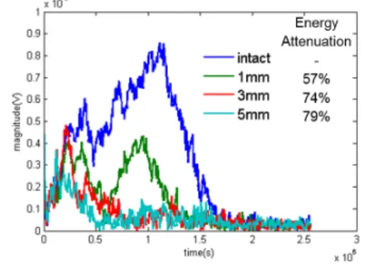
5 mm. The observation of Fig. 7 reveals that as
the crack depth increases, the amplitude of the
first arriving surface wave significantly decreases
in the time domain. Fig. 8 shows that this
signal attenuation mainly occurs in the high
frequency range of the signal. Although it is not
shown, the bulk waves are hardly affected by
Fig. 7 Change of the measured time domain signals due to an increasing surface crack
Fig. 8 Change of the measured frequency domain signals due to an increasing surface crack
the surface detect. Therefore, it may be feasible to detect rail surface damage using surface waves. However, it should be noted that 128 response signals are collected by repeating the pulse laser excitations, and averaged to improve the signal-to-noise ratio.
4.2 Subsurface Damage Detection
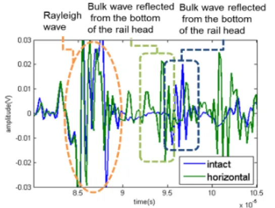
As described in Fig. 5, horizontal and vertical subsurface notches are simulated. For the case of the horizontal damage (see Fig. 9), the bulk wave traveling through the thickness direction reflected from this horizontal damage, creating the multiple bulk waves. Particularly the first arriving bulk wave reached the sensing point before the one from the intact condition.
Note that the reflection signal in the intact case
was generated at the bottom surface of the rail head due to the discontinuity between the rail head and the rail web. For the vertical crack in Fig. 10, the amplitude of the reflected bulk wave attenuated but did not generate any additional reflections.
4.3 Parameter Studies
- Surface ablation: The relationship between the peak power and ablation is investigated by adjusting the Q-Switch delay time of the Nd-Yag pulse laser. Note that as the delay time increase, the pulse energy of the pulse laser decreases as shown in Fig. 11. As shown in Fig. 12, the appearance of a spot ablation was clear at the time delay of 235 us, and then it gets weaker as the delay time increases. Although it is not shown here, it is also observed that ablation occurs as the number of repeated pulse excitations increases.
However, because this level of surface ablation does not compromise the integrity of rails for all practical purposes, it is often referred to as a cosmetic defect [6].
- Line vs. point source excitations: Using the line source excitation, surface waves are mainly generated and the appearance of the bulk waves was very small. Therefore, it was concluded that the lines source is better suited for surface crack detection and the point source is appropriate for subsurface damage detection.
- Effect of surface conditions: The surface
condition especially affects the noise level of
the laser Doppler vibrometer although the
Nd-Yag laser is less sensitive to the surface
condition. The best solution to improve the
signal-to-noise ratio would be to place a
retroreflective tape to the sensing point. In
this study, instead of treating the rail surface
Fig. 9 Change of the measured time domain signals due to a horizontal subsurface damage
Fig. 10 Change of the measured time domain signals due to a vertical subsurface damage
Fig. 11 The relation between the Q-switch time delay and the energy level exerted to the rail surface
Fig. 12 The relation between the Q-switch time delay and the rail surface ablation