Three-dimensional analysis of the distal movement of maxillary 1st molars in patients fitted with
mini-implant-aided trans-palatal arches
Objective: The aim of this study was to investigate three-dimensional molar displacement after distalization via miniscrews and a horizontal modification of the trans-palatal-arch (TPA). Methods: The subjects in this clinical trial were 26 Class II patients. After the preparation of a complete set of diagnostic records, miniscrews were inserted between the maxillary 2nd premolar and 1st molar on the palatal side. Elastic modules connected to the TPA exerting an average force of 150−200 g/side parallel to the occlusal plane were applied.
Cone-beam computed tomography was utilized to evaluate the position of the miniscrews relative to the adjacent teeth and maxillary sinus, and the direction of force relative to molar furcation. The distances from the central point of the incisive papilla to the mesiopalatal cusps of the 1st maxillary molars and the distances between the mesiopalatal cusps of the left and right molars were measured to evaluate displacement of the maxillary molars on the horizontal plane. Interocclusal space was used to evaluate vertical changes. Results: Mean maxillary 1st molar distalization was 2.3 ± 1.1 mm, at a rate of 0.4 ± 0.2 mm/
month, and rotation was not significant. Intermolar width increased by 2.9 ± 1.8 mm. Molars were intruded relative to the neighboring teeth, from 0.1 to 0.8 mm. Conclusions: Distalization of molars was possible without extrusion, using the appliance investigated. The intrusive component of force reduced the rate of distal movement.
[Korean J Orthod 2015;45(5):236-244]
Key words: Orthodontic anchorage procedures, Tooth movement, Dental models Amirfarhang Miresmaeili
a,bAhmad Sajedi
aAbbas Moghimbeigi
cNasrin Farhadian
aa
Department of Orthodontics, Faculty of Dentistry, Hamadan University of Medical Sciences, Hamadan, Iran
b
Hamadan Dental Research Centre, Hamadan University of Medical Sciences, Hamadan, Iran
c
Department of Biostatistics, Faculty of Public Health, Hamadan University of Medical Sciences, Hamadan, Iran
Received May 12, 2014; Revised April 19, 2015; Accepted May 12, 2015.
Corresponding author: Nasrin Farhadian.
Professor, Department of Orthodontics, Faculty of Dentistry, Hamadan University of Medical Sciences, Shahid Fahmideh Street, Hamadan 65168, Iran.
Tel +98-8118381085 e-mail [email protected]
© 2015 The Korean Association of Orthodontists.
The authors report no commercial, proprietary, or financial interest in the products or companies described in this article.
This is an Open Access article distributed under the terms of the Creative Commons Attribution Non-Commercial License (http://creativecommons.org/licenses/by-nc/4.0) which permits unrestricted non-commercial use, distribution, and reproduction in any medium, provided the original work is properly cited.
pISSN 2234-7518 • eISSN 2005-372X
http://dx.doi.org/10.4041/kjod.2015.45.5.236
INTRODUCTION
Class II malocclusion can be appraised as skeletal and dental Class II.
1The treatment of skeletal Class II malocclusion in non-growing individuals involves ei- ther surgical correction of the jaw abnormality, or orthodontic camouflage which usually requires the extraction of premolars or distal movement of the maxi- llary molars.
2,3For several years, extraoral appliances such as headgear were the most widely used distalizing appliances, but they are not esthetically desirable or socially acceptable, especially for adults. They are also removable and require patient compliance, which can compromise the results.
4Several intraoral noncompliance devices for maxillary molar distalization have been recommended since the 1980s.
5These include but are not limited to the Hil gers pendulum appliance, Jones jig distalization apparatus, open nickel-titanium (NiTi) push coils, distal jet, repelling magnets, and molar slider.
6-11Numerous side effects have been reported in association with these tooth-borne distalizing appliances, including anchorage loss of the maxillary premolars and flaring of the in- cisors, and a significant amount of relapse can occur.
Also, the distalized molars must be used for anchorage during retraction of the premolars and anterior teeth,
5resulting in a bite-opening effect that is not tolerable for most patients.
Temporary anchorage devices (TADs) have been inves- tigated, in an effort to overcome some of the side effects associated with tooth-borne distalizing appliances.
1Dental implants, miniscrews, and miniplates have been used for skeletal anchorage.
1,11-15TADs have several advantages. They are relatively easy to place, inflict less
trauma on the oral tissues, are stable under normal de- grees of force, and can bear force immediately after pla- cement.
Miniscrews, in particular, are relatively inexpensive and patient compliance is limited to maintaining good oral hygiene. Moreover, they exert immediate orthodontic force, reducing the total treatment time. Given their small size, they can be inserted in a variety of sites on the alveolar and basal bones.
3,16-19However, they have been associated with damage to anatomical structures such as dental roots, nerves, and blood vessels, and there are the possibilities of screw breakage on placement and removal, and screw failure with peri-implant infla- mmation. The reported success rates of miniscrews range from 80% to 95%.
20The placement of miniscrews in the buccal inter- radicular bone is one of the most common approaches used to provide skeletal anchorage. The interradicular space is a potentially advantageous region for insertion, because there is less potential for complications related to soft tissue irritation, particularly if they are placed through the attached gingiva.
20Although adjacent teeth may limit mesiodistal tooth movement, buccal in terdental miniscrews are very useful for molar dis- talization, due to their ease of placement, and simple application during treatment. With a properly positioned TAD, 3 mm of distal movement per side can be achieved.
21On the palatal side, a TAD may be placed paramedian (near the midline) or in the interdental space. While paramedian appliances usually require more expensive and sophisticated attachments, the risk of root damage associated with them is minimal.
1,6,12,22TADs placed on the palatal interdental area can apply distalization forces directly to the molar. Moreover, these TADs can
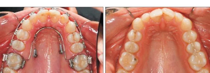
Figure 1. Mini-implant-aided trans palatal arch molar distalizing appliances include a horseshoe shaped palatal bar inserted in the palatal sheath, and two miniscrews between the 1st molar and 2nd premolar. They exert a traction force from the anterior helix to the miniscrews. A, Before the start of treatment; B, after the completion of distalization.
B
A
also control the mesiodistal axis of the molar via mani- pulation of the line of action.
22We have introduced a new appliance using palatal miniscrews “mimi-implant-aided (MIA) in the in terdental area between the 1st molar and 2nd premolar root and a trans-palatal arch (TPA) to overcome some of the mechanical shortcomings of previous appliances, in contexts including anterior protrusion, extrusion of posterior teeth, and tipping of molar teeth (MIA-TPA).
Traction between TADs in the palatal interdental area and a TPA can produce direct distalization force that travels through the center of resistance of molars (Figure 1). The purpose of the present study was to measure the three-dimensional (3D) movement of 1st molars after using this newly designed distalizing appliance.
MATERIALS AND METHODS
The sample group consisted of 26 patients (22 females, 4 males) with an average age of 19.8 ± 6.3 years (range 12 − 36 years) at the beginning of treatment (Table 1).
The main inclusion criterion was Angle Class II malo- cclusion of no more than one cusp on each side. Pa- tients with missing teeth, substantial restorations, or any craniofacial malformation were excluded from the study. The study was approved by the University Re search and Ethics Committee, and registered as a clinical trial at Iranian Registry of Clinical Trials (No.
IRCT201302269085N3). All patients (and their pa- rents in the case of minors) were informed about the treatment procedures involved, and informed consent was provided.
After preparing the initial diagnostic records including
Table 1. Baseline measurements and the participants’ principal measurements Number Anterior-posterior dental
relationship at T1 Gender Age (yr) Duration of
distalization (mo) Rate (mm/mo)
1 Half cusp Class II Male 19.7 4.0 0.53
2 Half cusp Class II Female 16.8 5.5 0.16
3 Full cusp Class II Male 14.7 4.5 0.75
4 Half cusp Class II Female 17.8 6.5 0.16
5 1/4 cusp Class II Female 15.7 5.5 0.81
6 Half cusp Class II Female 18.0 10.5 0.28
7 3/4 cusp Class II Female 18.5 9.0 0.23
8 Half cusp Class II Female 20.5 6.0 0.14
9 3/4 cusp Class II Female 20.5 13.0 0.17
10 Half cusp Class II Female 16.5 7.0 0.34
11 Half cusp Class II Female 26.7 5.5 0.52
12 Half cusp Class II Female 28.8 6.5 0.48
13 Half cusp Class II Female 15.8 5.0 0.17
14 Half cusp Class II Female 18.0 10.0 0.25
15 Full cusp Class II Female 23.9 9.5 0.23
16 Half cusp Class II Female 36.9 4.5 0.23
17 Half cusp Class II Male 12.8 14.0 0.13
18 Half cusp Class II Female 19.9 6.5 0.47
19 Full cusp Class II Male 13.3 4.5 0.47
20 Half cusp Class II Female 16.6 2.0 1
21 3/4 cusp Class II Female 21.6 7.0 0.43
22 Class I (Bimaxillary protrusion) Female 35.8 7.5 0.35
23 3/4 cusp Class II Female 24.0 7.0 0.19
24 3/4 cusp Class II Female 16.0 7.0 0.81
25 Half cusp Class II Female 12.5 5.0 0.39
26 Class I Female 14.0 4.0 0.64
dental casts, a dentist placed two miniscrews, each with a range of 8 − 10 mm in length and 1.4, 1.6, or 2.0 mm in diameter in the palatal interdental area under local anesthesia. Miniscrews were inserted between maxillary 2nd premolars and 1st molars with a self-tapping technique, approximately 5 − 6 mm from the gingival crest at an angle of 60 − 80
orelative to the long axis of adjacent teeth. The heads of the screws were app- roximately 2 mm above the mucosal surface, to facilitate the attachment of elastic modules. A palatal sheath was then placed on the 1st molar’s band. A TPA was made on a cast with stainless steel wire of 0.8 mm in diameter, with two helices or hooks soldered into the lateral incisors area. Final adjustment of the TPA was performed inside the patient's mouth.
Miniscrews were immediately placed under loading.
Miniscrews were loaded with an average force of 150 − 200 gram-force/side via elastic modules, and ligature wire was used to connect the TPA, almost parallel to the occlusal plane of the miniscrew. Elastic modules were replaced every 3 weeks, and TPAs were adjusted appropriately. All of the other teeth were bonded from 2nd molar to 2nd molar with standard edgewise brackets and tubes (Dentaurum, Ispringen, Germany), and leveling and aligning were performed before the termination of distalization to reduce any possible anchorage loss after distalization. The final arch wire was 0.018-in stainless steel. A cone-beam computed tomography (CBCT) scan (Newtom 3G; Quantitative Radiology, Verona, Italy) was performed to evaluate the precise position of mini screws relative to adjacent teeth and the direction of the force relative to molar teeth.
After maxillary 1st molars were driven to super Class I relationship, distalization was terminated and a final impression was taken for final evaluation. Digital model analysis of molars was used to evaluate changes in the 3D position of the maxillary molars. Digital scans of models before and after distalization were prepared via a Maestro 3D dental scanner (AGE Solutions S.r.l., Pontedera, Italy). Maestro Ortho Studio software version
2.5 (AGE Solutions S.r.l.) was used to analyze the digital models.
3D digital model and CBCT analysis
Reference points were used to analyze digital casts. The palatal rugae possesses unique characteristics, and as it tends to exhibit reasonable stability during growth, it may serve as a suitable reference point for longitudinal cast analysis.
23As the patients in the current study were not in an active growth period and no potential incisor movement was anticipated during the distalization period, as in Nalcaci et al.,
1the distance from the cen- tral point of the incisive papilla to the mesiopalatal cusp of the 1st maxillary molars was used to measure dis- talization. The distances between the mesiopalatal cusps of the left and right molars were measured to evaluate intermolar width. The angles between the incisive papilla and the distopalatal and mesiobuccal cusps of the 1st maxillary molars were measured to evaluate the rotation of maxillary molars
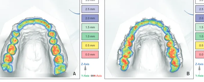
1(Figure 2). Interocclusal space at the mesiobuccal, distobuccal, and mesiopalatal cusps of the 1st maxillary molars was evaluated by occlusion inspection, and Maestro 3D scanner and software was used to evaluate vertical movement. After putting the casts in the maximum intercuspal position, the spa- ces between the maxillary 1st molar cusps and the antagonist tooth at T1 and T2 were measured via a 0.5- mm interval scale with a color coded tool (Figure 3).
For CBCT analysis, Digital Imaging and Communi- cations in Medicine (DICOM) files were imported to a Dolphin 3D 11 (Dolphin Imaging, Chatsworth, CA, USA). The orientation was adjusted in accordance with the palatal plane and midsagittal plane. Right and left sagittal and axial sections were prepared. In sagittal planes, a line was drawn along the helix in the TPA and miniscrew. The angle between this line and a line drawn parallel to the occlusal plane was measured on right and left 3D sagittal view. In 3D axial view, lines between the helix and the miniscrews on the right and left sides were drawn, and the angle between those lines (axial angle)
A B
36.3501 mm 29.3169 mm 30.2918 mm
62.9801 62.3873
Figure 2. The measurements
on digital models. A, Distance
between mesiopalatal cusps
of both side first molars and
incisive papilla; B, angle bet-
ween the lines connecting
in cisive papilla to distopalatal
cusp of the first molar and
mesiopalatal cusp to disto-
palatal cusp of the first molar.
was measured (Figure 4).
Statistical analysis
Descriptive statistics were used to examine the nor- mal distribution of the data. Measurements were re- peated one month after the initial measurements, and the reliability of the measurements was calculated via the intraclass correlation test. Reliability was bet- ween 79.7 and 97.0 for linear measurements, and bet- ween 93.8 and 96.6 for angular measurements. The paired t-test was used to compare measurements ac- quired before and after distalization in a digital cast.
A probability of p < 0.05 was deemed to indicate sta- tistical significance. Pearson’s correlation was used to evaluate the relationships between CBCT parameters and
digital cast parameters. Statistical Package for the Social Sciences ver. 13.0 (SPSS Inc., Chicago, IL, USA) was used for statistical analyses.
RESULTS
Maxillary 1st molars were moved distally an average of 2.3
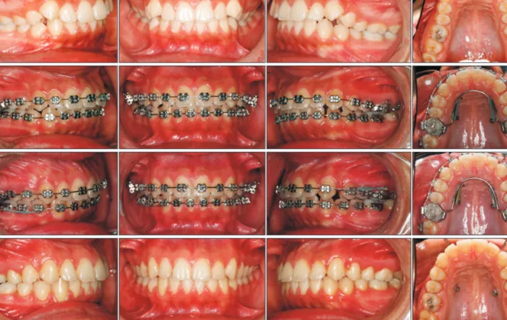
± 1.1 mm, and the difference between the right and left sides was not statistically significant (p = 0.63). The mean duration of distalization was 6.8 ± 2.8 months (range 2 − 14 months), thus the average rate of distalization achieved via the method utilized in the current study was 0.4 ± 0.2 mm/month. A representative case is shown in Figure 5.
Maxillary 1st molars were slightly rotated mesially Figure 4. Demonstrations of the lines of traction force by cone-beam computed tomography (CBCT) images. A, Right sagittal view; B, left sagittal biew; C, coronal view. In right and left sagittal views of the CBCT scan, the angle between the lines of traction from the helix to the minscrews relative to the occlusal plane clearly indicate the apical direction of distal driving force. The coronal view shows the divergent distal driving force as the expansion component of applied force.
A B C
17.9 7.17.1
50.8 50.8
Figure 3. Evaluation methods of vertical teeth movement by three-dimensional digital model. A, Before treatment;
B, after treatment. The red areas are contact areas, which are more marked on the right first maxillary molars before treatment than after treatment. Red marks are stronger on premolars and second molars after treatment, which is an additional sign of first molar intrusion.
3.0 mm
2.5 mm
2.0 mm
1.5 mm
1.0 mm
0.5 mm
0.0 mm
Z-Axis
Y-Axis X-Axis
3.0 mm
2.5 mm
2.0 mm
1.5 mm
1.0 mm
0.5 mm
0.0 mm
Z-Axis
Y-Axis X-Axis